
Related Manuals for Schaffner FN5420


Summary of Contents for Schaffner FN5420
- Page 1 USER AND INSTALLATION MANUAL Output Filters FN5420 and Reactors RWK5420 Schaffner EMV AG Nordstrasse 11e 4542 Luterbach Switzerland Main +41 32 681 66 26 schaffner.com...
- Page 2 Other technical documentation of our products is also available in the download area of our website schaffner.com. Document name: User and installation manual Output Filters FN5420 and Reactors RWK5420 rev05.pdf Valid for Output Filters FN5420 and Reactors RWK5420 version: sine wave filter FN5420 (all versions)
- Page 3 Schaffner sine wave filters help to avoid problems that can result in purely functional difficulties to very severe motor damage. Sine wave filters FN5420 series offer state of the art motor protection for the most demanding applications. By installing a sine wave filter between your drive and motor: ▪...
- Page 4 Important user notice Schaffner sine wave filters are designed for the operation on the output (motor) side of converters, such as AC or DC motor drives. Filter suitability for a given application must be determined by the user on a case-by-case basis.
- Page 5 General Safety Notes and Installation Guidelines (Cautions and Warnings) User and installation manual Output Filters FN5420 and Reactors RWK5420 4/52...
-
Page 6: Table Of Contents
Thermal protection switch specifications ........... 24 Cooling requirement ..................24 Mechanical data ..................... 25 3.8.1 Dimensions FN5420 IP00 ....................25 3.8.2 Dimensions FN5420 IP20 ....................30 3.8.3 Dimensions RWK5420 ......................32 5/52 User and installation manual Output Filters FN5420 and Reactors RWK5420... - Page 7 Connect monitor switch TS- TS’ ..................48 5.3.8 6 Filter maintenance ................. 49 Maintenance schedule .................. 49 Fan ........................49 Power capacitors ................... 50 Electrical connections ................... 50 7 Troubleshooting ................51 User and installation manual Output Filters FN5420 and Reactors RWK5420 6/52...
-
Page 8: Sine Wave Filter Fn5420 Designation
3.1 below. ▪ The fourth part of the designation ‘FN5420-xxx-yy-E_ _ _ _’ contains 4 slots, the first is the IP degree of protection, second, the presence of active ventilation (fan), third the presence of a power supply for the fan (if present) and the last one indicates the presence or not of a temper- ature switch. -
Page 9: Dv/Dt Reactor Designation
50Hz, with terminal type 99 (bus bar), rated IP00, without fan nor power supply and with temperature switch. 1.3 Additional Resources The Schaffner group does provide a number of additional resources available at schaffner.com to understand power quality in general and product in particular. 1.4 Naming convention... -
Page 10: Filter Selection
Schaffner output filters need to be selected according to the applications specifications and needs. Step 1: motor frequency Sine wave filter FN5420 series and dv/dt reactor RKW5420 series work at rated current up to a motor frequency of 60Hz and with a derating up to 200Hz, see derating in section 2.4.2. - Page 11 Dv/dt reactor RWK5420 series doesn’t have any minimum fPWM but is still limited to the same maximum fPWM than sine wave filter FN5420 series. The maximum switching frequency must be reduced according to the cable length or the cable length must be limited for a given switching frequency. These limits are giving in the Table 3 and Figure 4 below and in the datasheet.
- Page 12 In case of problem with bearing current, sine wave filter plus addons type FN5030 would eliminate the flashover created at switching, increasing even more the bearing total lifetime. 11/52 User and installation manual Output Filters FN5420 and Reactors RWK5420...
-
Page 13: Filter Selection Table Fn5420 Ip00
**** See section 3.3 for calculation of the filter power loss at other operation point. Exact value depends on the motor cable length and type, switching frequency and further stray parameters of the system. User and installation manual Output Filters FN5420 and Reactors RWK5420 12/52... -
Page 14: Filter Selection Table Fn5420 Ip20
**** See section 3.3 for calculation of the filter power loss at other operation point Exact value of the complete system depends on the motor cable length and type, switching frequency and further stray parameters of the system. 13/52 User and installation manual Output Filters FN5420 and Reactors RWK5420... -
Page 15: Filter Selection Table Rwk5420
See section 3.3 for calculation of the filter power loss at other operation point Exact value of the complete system depends on the motor cable length and type, switching frequency and further stray parameters of the system. User and installation manual Output Filters FN5420 and Reactors RWK5420 14/52... -
Page 16: Derating
2.4.1 Temperature derating All sine wave filter FN5420 series and dv/dt reactor RWK5420 series are able to operate at rated current up to an ambient temperature of 45°C (measured next to the device, i.e. inside a cabinet). It is possible to use the filter and reactor above this limit, but a derating must be applied on the maximum current going through the filter. -
Page 17: Motor Frequency Derating
2.4.2 Motor frequency derating All sine wave filter FN5420 series and dv/dt reactor RWK5420 series can operate at rated current for a motor frequency up to 60Hz. They can also operate in case of increased motor speed with motor frequency up to 200Hz by applying a derating on the maximum current allowed in the filter or reactor. -
Page 18: Filter Description
Repetitive tests performed max. above levels, seconds. Magnetic current gives the limit of saturation, above this value the performance cannot be guarantee. See applicable derating in section 2.4.1 17/52 User and installation manual Output Filters FN5420 and Reactors RWK5420... -
Page 19: General Electrical Specifications Rwk5420
Repetitive tests performed max. above levels, seconds. Magnetic current gives the limit of saturation, above this value the performance cannot be guarantee. See applicable derating in section 2.4.1 User and installation manual Output Filters FN5420 and Reactors RWK5420 18/52... -
Page 20: Power Losses
Figure 6 power loss calculation chart 3.3.1 Power loss calculation example For a system using a sine wave filter type FN5420-45-92-E0XXT you take the typical power loss given in Table 4, 272W. This typical power loss is for 400/500V 50Hz at nominal current of 45A. -
Page 21: Additional Electrical Specifications
3.4 Additional electrical specifications Schaffner output filter type sine wave filter FN5420 and dv/dt reactor type RWK5420 general electrical specifications refer to operating altitudes up to 2000m a.s.l. (6600ft). Operation between 2000m and 4000m (6600ft and 13123ft) requires a derating on clearance according to IEC 60664-1 (table A.2), hereafter enclosed:... -
Page 22: Screw Size, Torque And Cable Cross-Section Requirement
In many applications a shielded motor cable may not be required when a sine wave filter is applied with a motor drive. Anyhow, due to other possible influences of common mode disturbances Schaffner does recommend using shielded motor cables. This is to avoid back-coupling of radiated interferences to the mains cable at the frequency range from 1–30 MHz. - Page 23 Flex wire [mm²] 0.5 - 6 0.5 - 10 6 - 25 16 - 50 1.5 – 1.8Nm Recomm. torque 1.0 - 1.2Nm 4.0 - 4.5Nm 7.0 - 8.0Nm User and installation manual Output Filters FN5420 and Reactors RWK5420 22/52...
-
Page 24: Auxiliary Signal And Earth Terminals
No connector 0.5 - 6 24 - 10 0.5 - 4 0.7 - 0.8 Table 13 Table 10 Auxiliary signal terminals on FN5420 IP00 and RWK5420 Type 2.3A & 3.1A 5.9A to 18A 26A to 1000A Fork cable shoe M3.5 width max. -
Page 25: Thermal Protection Switch Specifications
1.8A cosϕ = 0.4-0.5 3.7 Cooling requirement Sine wave filter FN5420 IP20 come with embedded ventilation when needed. Thus, it is important to install the filter in a way that the air channels are not blocked and within an ambient temperature according to the specifications from section 2.2. -
Page 26: Mechanical Data
The drawings of each design is presented below. Dimensions are given in Table 15. Figure 9 drawings FN5420 IP00 sizes 2.3A to 3.1A Figure 10 drawings FN5420 IP00 sizes 5.9A to 18A 25/52 User and installation manual Output Filters FN5420 and Reactors RWK5420... - Page 27 Figure 11 drawings FN5420 IP00 sizes 26A to 60A Figure 12 drawings FN5420 IP00 sizes 75A to 110A User and installation manual Output Filters FN5420 and Reactors RWK5420 26/52...
- Page 28 Figure 13 drawings FN5420 IP00 sizes 145A to 400A Figure 14 drawings FN5420 IP00 sizes 480A to 800A 27/52 User and installation manual Output Filters FN5420 and Reactors RWK5420...
- Page 29 Figure 15 drawings FN5420 IP00 size 1000A User and installation manual Output Filters FN5420 and Reactors RWK5420 28/52...
- Page 30 387 24x11 max. 152 ø13.5 max. 430 24x11 max. 152 ø13.5 max. 434 24x11 max. 152 ø13.5 24x11 ø13.5 24x11 ø13.5 24x11 ø13.5 24x11 ø13.5 1000 1050 24x11 ø13.5 29/52 User and installation manual Output Filters FN5420 and Reactors RWK5420...
-
Page 31: Dimensions Fn5420 Ip20
3.8.2 Dimensions FN5420 IP20 The drawings of each design is presented below. Dimensions are given in Table 16. Figure 16 FN5420 IP20 sizes 2.3A to 38A User and installation manual Output Filters FN5420 and Reactors RWK5420 30/52... - Page 32 Figure 17 FN5420 IP20 sizes 45A to 110A Table 16 dimensions FN5420 IP20 Frame Drill pattern Base Box size Type R +2/0 X ±2 Z ±2 Dimensions in mm For Dimensions without Tolerances: ISO2768-m/EN22768-m applies 31/52 User and installation manual Output Filters FN5420 and Reactors RWK5420...
-
Page 33: Dimensions Rwk5420
3.8.3 Dimensions RWK5420 The drawings of each design is presented below. Dimensions are given in Table 17. Figure 18 RWK5420 sizes 2.3A to 3.1A Figure 19 RWK5420 sizes 5.9A to 18A User and installation manual Output Filters FN5420 and Reactors RWK5420 32/52... - Page 34 Figure 20 RWK5420 sizes 26A to 60A Figure 21 RWK5420 sizes 75A to 110A 33/52 User and installation manual Output Filters FN5420 and Reactors RWK5420...
- Page 35 Figure 22 RWK5420 sizes 145A to 1000A User and installation manual Output Filters FN5420 and Reactors RWK5420 34/52...
- Page 36 ø11 24x11 12.5 ø11 24x11 ø13.5 24x11 ø13.5 24x11 ø13.5 24x11 ø13.5 722 +/-10 24x11 ø13.5 693 +/-10 24x11 ø13.5 821 +/-10 24x11 ø13.5 1013 +/-10 24x11 ø13.5 1000 35/52 User and installation manual Output Filters FN5420 and Reactors RWK5420...
-
Page 37: Functional Diagram
Chokes L Power magnetic components incl. temperature sensors Capacitors C Power capacitors Field replaceable fan for choke air cooling Power supply Internally generate 24 V DC source for fan supply User and installation manual Output Filters FN5420 and Reactors RWK5420 36/52... -
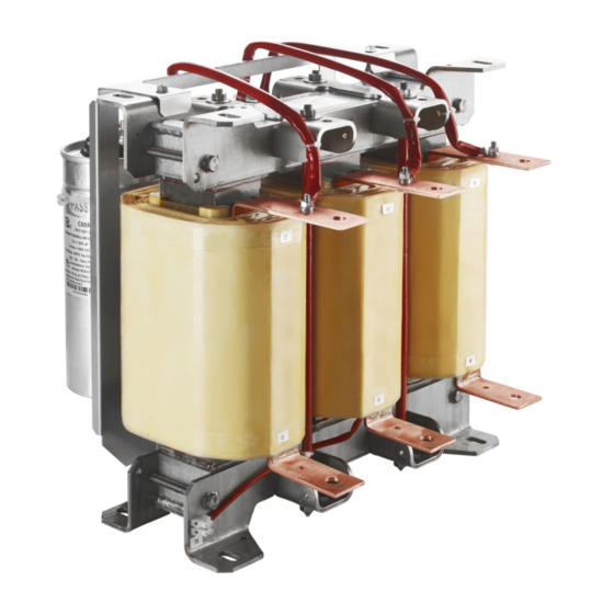
Page 38: Filter Appearance And Elements
Some selected examples of design will be detailed in this chapter to help the user locate the important parts of the product. Example of design of sine wave filter FN5420 and RWK5420 are shown in Figure 25 to Figure 33 with relevant elements indicated on the drawing. - Page 39 Figure 27 Design of FN5420 IP00 75A (apply for 75A to 110A) Figure 28 Design of FN5420 IP00 400A (apply for 145A to 1000A) User and installation manual Output Filters FN5420 and Reactors RWK5420 38/52...
- Page 40 Figure 29 Design of FN5420 IP20 frame B (apply for frame A and B, 2.3A to 10A) Figure 30 Design of FN5420 IP20 frame C (apply for frame C 13A to 38A) 39/52 User and installation manual Output Filters FN5420 and Reactors RWK5420...
- Page 41 Figure 31 Design of FN5420 IP20 frame D (apply for frame D and E, 45A to 110A) Figure 32 Design of RWK5420 60A (apply for 26A to 60A) User and installation manual Output Filters FN5420 and Reactors RWK5420 40/52...
- Page 42 Figure 33 Design of RWK5420 75A (apply for 75A to 1000A) 41/52 User and installation manual Output Filters FN5420 and Reactors RWK5420...
-
Page 43: Filter Installation
Please note that the following installation steps are applicable for sine wave filter FN5420 series IP00 and IP20 as well as dv/dt reator RWK5420 series. - Page 44 Apply torques appropriate for the strength class of the screws and washers you are using. Specifications can be obtained from the supplier of the screws and washers. 43/52 User and installation manual Output Filters FN5420 and Reactors RWK5420...
- Page 45 (e.g. cabinet cooling). Filter >150mm operation environments with higher >100mm temperatures require a temperature derating (see section 2.4.1). >100mm >150mm Figure 39 Minimum distance for wall mounted devices User and installation manual Output Filters FN5420 and Reactors RWK5420 44/52...
-
Page 46: Prepare The Fixation
For sine wave filters FN5420 IP00 series refer to the dimensions E,D and F from the matching drawing and table in section 3.8.1 For sine wave filters FN5420 IP20 series refer to the dimensions R, S and T from the matching drawing and table in section 3.8.2. - Page 47 Place filter first onto lower screws… ...then position it through backplane head openings on upper screws. 5. Fix screws with appropriate torque (depending upon the material of the back plane and local standards). User and installation manual Output Filters FN5420 and Reactors RWK5420 46/52...
-
Page 48: Step 3: Wiring
An example shielding connection system is given in Figure 8 in section 3.5. 47/52 User and installation manual Output Filters FN5420 and Reactors RWK5420... -
Page 49: Connect Shielding For Shielded Cables
INVESTIGATION OF THE respective input of drive control (check drive manual) or as PROBLEM. alarm sensor for system control unit. User and installation manual Output Filters FN5420 and Reactors RWK5420 48/52... -
Page 50: Filter Maintenance
Forced cooling devices are needed for the operation of Schaffner output filters up to their nominal rating. Such cooling devices must be checked and cleaned regularly (if installed) to ensure sufficient air flow at all times. -
Page 51: Power Capacitors
Therefore, Schaffner recommends checking and tighten all electrical connections on the occasion of a regular scheduled maintenance entire device that incorporates filter. Check of internal connections within the filters is not needed or should be conducted by a Schaffner service representative. User and installation manual Output Filters FN5420 and Reactors RWK5420 50/52... -
Page 52: Troubleshooting
In the unlikely event of a problem, please contact your local Schaffner partner for assistance. 51/52 User and installation manual Output Filters FN5420 and Reactors RWK5420... - Page 53 Schaffner group companies (“Schaffner”) and do not constitute an offer for purchase or sale or a recommendation or advice. The content of this document has been carefully prepared and reviewed and all reasonable efforts have been made to ensure the accuracy of the information.
- Page 54 Schaffner EMV AG Nordstrasse 11e 4542 Luterbach Switzerland Main +41 32 681 66 26 schaffner.com...
Need help?
Do you have a question about the FN5420 and is the answer not in the manual?
Questions and answers