
Subscribe to Our Youtube Channel
Related Manuals for Garland P10GSFPA


Summary of Contents for Garland P10GSFPA
- Page 1 User Guide P10GSFPA 03/2023 Version 4.24.1 Garland Technology | 716.242.8500 | www.garlandtechnology.com/support Copyright © 2023 Garland Technology, LLC. All rights reserved.
- Page 2 The Garland Technology trademarks, service marks ("Marks") and other Garland Technology trademarks are the property of Garland Technology, LLC. PacketMAX Series products of marks are trademarks or registered trademarks of Garland Technology, LLC. You are not permitted to use these Marks without the prior written consent of Garland Technology.
-
Page 3: Table Of Contents
Breakout Mode Aggregate Mode Aggregate 2 Mode Span Mode Span Packet Inject Mode Rear Panel LED Indications Switch Settings Installation Procedure Optional Rack Mount Bracket Garland Technology | 716.242.8500 | www.garlandtechnology.com/support Copyright © 2023 Garland Technology, LLC. All rights reserved. -
Page 4: P10Gsfpa
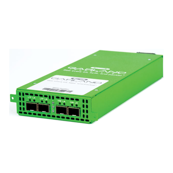
This document describes the front panel, LED indications, interfaces, rear panel, rear switch and installation procedure for the P10GSFPA. The unit supports five application modes; bypass, breakout, aggregate, span and span packet inject. LFP and Fail Mode (open) are supported on the network ports for the bypass, breakout and aggregate modes. -
Page 5: Interfaces
Ingress Span Port 2 / Port 3 / Port 4 Port 2 Span Port Ingress Port 1 Port 3 Span Port Ingress Port 1 Port 4 Span Port Ingress Port 1 Garland Technology | 716.242.8500 | www.garlandtechnology.com/support Copyright © 2023 Garland Technology, LLC. All rights reserved. -
Page 6: Span Packet Inject Mode
Port 4 Span Port Ingress Port 1 Packet Inject Port Egress Port 1 Rear Panel LED Indications Power Supply 1 LED Power Supply 2 LED Garland Technology | 716.242.8500 | www.garlandtechnology.com/support Copyright © 2023 Garland Technology, LLC. All rights reserved. -
Page 7: Switch Settings
* LFP is not supported for 1G and 10G copper applications. Switch 2 Off. * The unit must be power cycled if the switch settings are modified. Garland Technology | 716.242.8500 | www.garlandtechnology.com/support Copyright © 2023 Garland Technology, LLC. All rights reserved. -
Page 8: Installation Procedure
Installation Procedure 1. T he P10GSFPA may be installed in any available 1U slot of a network rack and secured with rack mount screws or in the optional rack mount bracket, sold separately. The optional rack mount bracket is shown below.
Need help?
Do you have a question about the P10GSFPA and is the answer not in the manual?
Questions and answers