Advertisement
Quick Links
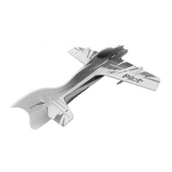
Manual – Pilot-RC Foamy
1- Introduction:
WELCOME TO THE PILOT-RC TEAM!
Thank you for choosing a Pilot-Rc plane as your next model. We hope that you
enjoy many successful and exhilarating flights with your new plane. Please read
through these instructions before you start building or flying to assure a successful
experience, and welcome to Team Pilot-Rc!
YOUR MODEL:
Model:
Wingspan:
Length:
Weight without electronics
Pilot-RC
33" (840
35" (886
3.6oz (10
Advertisement

Related Manuals for Pilot RC Foamy


Summary of Contents for Pilot RC Foamy
- Page 1 Manual – Pilot-RC Foamy 1- Introduction: WELCOME TO THE PILOT-RC TEAM! Thank you for choosing a Pilot-Rc plane as your next model. We hope that you enjoy many successful and exhilarating flights with your new plane. Please read through these instructions before you start building or flying to assure a successful...
-
Page 2: Included Hardware
Flying weight: 7.4-9.8oz INCLUDED HARDWARE: Complete air frame in pre-printed high visibility color scheme • Carbon rods to give the airframe structure and strength • Pushrods, control horns, wheels and other small accessories • Also available: PNP Combo. Includes model plus motor, speed controller, prop and servos REQUIRED HARDWARE: Motor: 2207-1680kv... - Page 3 model. As such all responsibility for the correct build, maintantence and operation must be accepted by the customer. The operation of the model is taken as acceptance by the customer of their acceptance to the above. The model is highly prefabricated and ready for use, however please also assure that any pre-installed (such as pushrodand ball link sets, fuel tank, etc) components are tight, secure and airworthy both for the first flight and subsequent flights as part of your routine maintenence and verification.
- Page 4 CARBON REINFORCEMENTS Before starting the assembly of the model, we need to add some rigidity to the foam. This is done through the addition of the provided carbon fibre. The leading edge of the wing, the center of the wing, the elevator, the underside of the fuselage and the intersection of the landing gear all need to be...
- Page 5 reinforced by gluing the provided carbon fibre rods in place. This is done using cyano glue and kicker. Don’t try and do large sections at once, it is recomendable to glue little by little, and assure a strong bond throughout. The carbon on the underside of the fuselage can be left long and used as a tail skid.
- Page 10 HINGES Make sure to leave roughly enough gap between the two surfaces to allow for maximum deflection. Once in place test for maximum deflection, then glue in place with cyano.
- Page 11 ASSEMBLE THE HORIZONTAL PANES With the model now suitably rigid and hinged, we can start assembling the parts together. Join up all horizontal parts and glue with cyano. This is the elevator, the center section of the fuselage, the wing and the nose section...
-
Page 14: Reinforce The Wing
ATTACH THE LOWER SECTION OF THE FUSELAGE Flip the now joined together horizontal parts so they are upside down, and slot in the lower section of the fuselage into the pre-cut slots and glue with cyano. In doing this, make sure that the fuselage is both straight and at 90º right angles with the rest of the flat horizontal parts. - Page 17 REINFORCE THE UNDERSIDE OF THE FUSELAGE Continuing with the cross bracing, additional carbon rods are used to provide strength from the wing joint (the tip of the carbon “X” reinforcement from the wing) all the way back to the tail of the model. This prevents the tail from twisting in flight.
- Page 18 These round carbon rods are the smaller diameter ones provided with your kit. Criss-cross carbon rods between the vertical and horizontal sections of the fuselage until reaching the elevator...
-
Page 21: Install The Landing Gear
INSTALL THE LANDING GEAR The landing gear is made up from carbon rod, crossed at the vertical fuselage to create another “X” shape. The small red parts allow to glue two parts of carbon rod together at the correct angle to be used as wheel axles. - Page 22 Once you slide the wheels over these “axles” secure in place with the small red washers and fix with cyano, being careful not to stick the wheel also.
-
Page 26: Install The Servos
INSTALL THE SERVOS Flip the model right side up and slot the servos into their diverse locations using your preferred method (cyano, hot glue, epoxy…) It is important to do this before attaching the top half of the fuselage, as this top section will “lock”... - Page 27 ATTACH THE FUSELAGE TOP SECTION Slot in the top section of the fuselage into the pre-cut slots and glue with cyano. In doing this, make sure that the fuselage is both straight and at 90º right angles with the rest of the flat horizontal parts. If you don’t have a square edge, you can use business cards or similar objects with perfect right angles.
- Page 30 REINFORCE THE RUDDER Additional carbon rods are used to provide strength from the elevator (already rigid thanks to the underside cross bracing) to the rudder. This prevents the rudder from twisting in flight. These round carbon rods are the smaller diameter ones provided with your kit.
-
Page 32: Install The Motor
INSTALL THE MOTOR Screw the motor onto the provided motor mount, and glue to the fuselage with a good amount of cyano glue. If preferred, rather than screwing the motor, you can also tie it in place using high tensile string and cyano. -
Page 34: Install The Control Horns
INSTALL THE CONTROL HORNS Slide the control horns into each of the flying surfaces, and glue in place using cyano in anticipation of connecting them with the servos. - Page 35 Note that there are a total of four control horns, of which there are two singles and two doubles. The singles are for both ailerons, while rudder and elevator are double horns to be used with pull-pull.
- Page 38 CONNECT THE AILERON SERVO TO THE SURFACES Using the control horns from the previous step, make up what will be the pushrods for the two ailerons. These are made from the provided carbon rods, and metal rod “Z bends” which will fit into both the servo arm and the control horn.
- Page 39 Make sure to have the correct measurements, and glue the Z bends onto both ends of the carbon pushrod. In order to provide strength to this join, it is vital that it is also wrapped with the high tensile string provided, and then soaked in cyano. This can all be hidden later with heatshrink tube.
- Page 40 CONNECT THE ELEVATOR AND RUDDER SERVOS TO THEIR SURFACES The rudder and elevator are connected to their servos through pull-pull. Tie two pieces of the high tensile string provided to the control horn (one on each side) and run to the servo. Instead of directly securing to the servo, which would allow for no adjustment, measure the distance required, and at a little longer than necessary, glue the string to a small screw that can then be screwed to the servo arm.
- Page 42 ADD THE SIDE FORCE GENERATORS Attach the various foam side force generators to the model using cyano. These provide improved airflow and lateral flight characteristics. They also provide improved strength and resistance to twisting in flight.
- Page 44 INSTALL YOUR RECEIVER AND BATTERY Locate the best location for your receiver and battery to assure a correct center of gravity, and fix in place using velcro or your preferred method. BALANCING THE CG OF AIRPLANE:...
-
Page 45: Double Check
The CG is located 150mm back from the leading edge of the wing at the center of the fuselage. Personal CG preference can be adjusted following the first flight. CONTROL THROW DEFLECTIONS AND SUGGESTED EXPO. General flying: Surface Deflection Ailerons: 20º...
Need help?
Do you have a question about the Foamy and is the answer not in the manual?
Questions and answers