Advertisement
Quick Links
Advertisement

Related Manuals for Pilot RC EDGE540


Summary of Contents for Pilot RC EDGE540
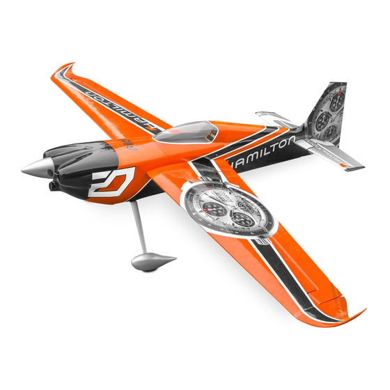
- Page 1 PilotRC EDGE540 67” USER MANUAL WINGSPAN:1710mm LENGTH:1554mm...
- Page 2 Introduction Thank you for purchasing our Edge 540 plane. we strive to achieve a good quality quick build ARF aircraft . It requires the least amount of assembly of any ARF kit to obtain the maximum performance. Both the design and manufacturing have been undertaken to the highest standards, using best quality hardware, covering, wood &...
- Page 3 Included Hardware: • Complete air frame with all basic accessories (such as carbon fibre main undercarriage, tail-gear assembly and wing-tube as well as fibreglass control horns and wheel pants) • Pre-installed hinges and pre-mounted canopy • Wheels, axels and wheel pants •...
- Page 4 Main Landing Gear Assembly Position the fuselage upside down and screw on the carbon undercarriage to the fuselage using the nuts and bolts provided. Screw the wheel axles on to the landing gear, and then slide on the wheels and secure in place with the provided grub screws. Some users may prefer to leave the wheels until the end of the build, to prevent the model moving on the build table.
- Page 5 Tail wheel Installation With the model still upside down, position the carbon tail wheel unit on its correct location and mark on the underside of the fuselage to drill the holes for the screws that will hold the tail wheel in place. Screw the tail wheel unit to the fuselage using the blind nuts and bolts provided.Attach the springs to the underside of the rudder using the metal arm supplied.
- Page 6 Servo Horn On The Elevator Installing: It is very important to sand horn to assure a strong bond once glued to the model. Locate and cut the covering where the horns will be glued Glue them to the surface using epoxy glue Excess epoxy glue can be removed with acetone...
- Page 7 Servo Horn On The Rudder Installing: It is very important to sand horn to assure a strong bond once glued to the model. Locate and cut the covering where the horns will be glued Glue them to the surface using epoxy glue Excess epoxy glue can be removed with acetone Servo Horn On The Ailerons Installing: It is very important to sand horn to assure a strong bond once glued to the...
- Page 8 Aileron Servo Installation: Locate and cut the covering where the servos will be installed. Route the servo wire through the wing and screw the servo in place. Centre the servo with your transmitter, attach the servo arm and connect the servo to the ailerons with the pushrods provided.
- Page 9 Stabilizer installation: Cut free the trailing edge of the vertical rudder in line with the stabiliser, in order to allow you to slide the stabiliser into the fuselage. Keep the removed section for later. Trial fit the stabiliser into the fuselage. Make sure that it is centered (measure the tip of the stabiliser to the tip of the wing on both sides and make sure they are the same distance) and correctly aligned (looking at wings and stabiliser, should show all being parallel)
-
Page 10: Rudder Servo Installation
Rudder Servo Installation: Centre the servo, attach the servo arm and connect the pull-pull wires to the servo using the accessories included, securely crimping the wires with the brass tubing, then cover with heat shrink. Position the other end of the wires through the rudder horn, pull the wires tight and crimp as before. -
Page 11: Motor Installation
Motor Installation: Follow the laser diagram on the firewall to drill the necessary holes for the motor. These are designed for use with the Pilot-RC CC20 motor. If using a different motor, hole position may vary. Check if your engine requires any standoffs in order to reach the necessary position, before attaching permanently to the model using bolts and blind nuts as per the images. - Page 12 Motor Installation: Replace the cowling with the screws Measure the distance for the motor installation Verification for clearance gap, should be about 1 to 1.5 cm Follow the same procedure for petrol engine...
- Page 13 Gas Engine Installation: Install the the plastic support to the fuselage, use the mounting screws to tightening it. Install the engine Validate the required space between the engine cowl and the propeller bed before permanently installing the engine in place...
- Page 14 Gas Engine component Installation: After engine installation,then you can install the engine components like battery, oil tank, receiver, and engine servo(include the servo arm, linkage. ect) in fuselage. Before install these components, check the correct location of components depending on your CG.
- Page 15 Gas Engine component Installation: Locate the appropirate hole and install the fuel dot in the side of the fuselage Screw the ignition switch to the side of the fuselage through the appropriate hole, or install an electronic ignition kill switch.
- Page 16 Cowling Installation: The cowling is secured using two separate methods. The top half is secured with screws installed through the canopy hatch opening, while the bottom half is scured with two screws installed from the outside. Place the model upside down and put masking tape next to the two blind nuts that will secure the bottom half of the cowl.
- Page 17 Ancillary Components Installation: Check the correct location of your chosen battery depending on your Glue Velcro strip to the battery tray (and battery), as well as threading a velcro strap round the battery tray, assuring a completely secure battery once fully installed. Finally install your receiver with double sided tape or velcro, making sure that all servo leads can be easily connected without being too tight, and that the receiver is securely fixed in place.
- Page 18 Wheels Installation: Slide the wheel pants over the wheels and axles, supporting the rear of the pants to line up with the ground and mark where to drill the two screw holes in the wheel pants. Remove the wheel pants and drill the holes for the appropriate holes. Before putting back on the plane, mount the bolt with the blind nut on the wheel pant and tighten until the nut sits flush with the wheel pant.
- Page 19 Balance CG of Airplane: Install the two balance rods in their position as shown in the picture below Loop some wire/string over the rods between on the outside of the fuselage (between fuselage and wing)Install the canopy and all final components and accessories Lift the model by the wire/string and this should balance.
- Page 20 Final presentation of your model :...
-
Page 21: Flight Preparation
Flight Preparation ■ Make sure you have the right model programmed into your transmitter ■ Check the direction of each surface not and also right before you take off . ■ Remember nothing wrong on the ground ever improves in the air ■... - Page 22 Zhongshan Pilot Model Aircraft Product Ltd Address: No.34, Chengnan Er Road, Zhongshan city, 528455, Guangdong Province, China Web: www.pilot-rc.com Email: pilot-rc@139.com, info@pilot-rc.com Tel: +86-760-88781293 FAX: +86-760-88780293...
Need help?
Do you have a question about the EDGE540 and is the answer not in the manual?
Questions and answers