
Related Manuals for Pilot RC 30cc 88" Skywolf


Summary of Contents for Pilot RC 30cc 88" Skywolf
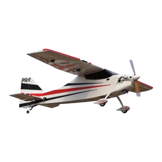
- Page 1 Assembly Manual For 30cc 88” Skywolf Wingspan: 88 in Wingarea: 1479.8 sp in Length: 78.8 in Engine: 50CC www.pilot-rc.com Note: some photos on the manual is not from Skywolf. But the installation way is the same.
-
Page 2: Introduction
Freestyle and aerobatic flying. We hope that every effort and service we offer will, in turn, give you confidence using PILOT Models. Have a wonderful time flying your 3D aircraft in a suitable safe space! More information on website www.pilot-rc.com... -
Page 3: Warranty
Model airplane owners use our products at their own risk. ■ Pilot-RC will not be liable for any costs, unless agreed and proved beyond doubt the failure was due to faulty materials or fabrication. Any agreed cost will not exceed the cost of the airframe and not include engine, radio equipment or third party claims. -
Page 4: Attention
Academy of Model Aeronautics (AMA Pilot-RC has the right to revise the plane, the instructions and the limited warranty without notice. If you have any problems and questions please contact Pilot –RC at: Email: pilot-rc@139.com... -
Page 5: Table Of Contents
INDEX ………………….………..….…….…. Introduction …………………….……..….…..……. Warranty …………….…………..….……..……. Attention Fuselage Unit Stabilizer/Elevator Assembly …………………………. ………..…….…...…….. Elevator Control Horns vertical tail/ rudder Assembly . ………………………. ………..…….…...…….. Elevator servo ………..…….…...……. Rudder Control Horns …………..……..Tail Wheel Installation Landing Gear Assembly ………….…..……. Main Landing Gear Installation …………..….………... -
Page 6: Stabilizer/Elevator Assembly
Stabilizer/Elevator Assembly 1. Cut the covering of the slot for 3. Inset the stabilizer to the stabilizer. slot. 4. Measure both left and right 2. Take out the elevator from the side as the photo shows. Be stabilizer. sure both side are the same size. - Page 7 Stabilizer/Elevator Assembly 5. Measure both left and right side 7. Using a modeling knife, cut as the photo shows. Be sure length along the marked lines and A=B. remove the covering. Repeat on the bottom of the stab. 8. Apply 30-minute epoxy to 6.
- Page 8 Stabilizer/Elevator Assembly 8. Before the epoxy cures, 10. Before the epoxy cures, Measure both left and right side as adjust the stab and wing to be the photo shows. Be sure both side parallel . This is very important. are the same size. 9.
- Page 9 Stabilizer/Elevator Assembly 11. Mix some “30-minute epoxy” and glue one side of the hinge to the elevator. 12. After the elevator glue cured. Apply 30-minute epoxy to the elevator to the stabilizer. Be sure the stabilizer glue cured on the fuselage before you do this.
-
Page 10: Vertical Tail/ Rudder Assembly
vertical tail/ rudder Assembly 1. The fin was glued with the 3. Apply some “30-minute rudder in factory. epoxy” to the fin slot on the fuselage. 4. Measure both left and right side as the photo shows. Be 2. Cut and move the covering sure both side are the same which need to glue to the fuselage. - Page 11 vertical tail/ rudder Assembly 5. Before the epoxy cures, adjust the fin and stabizlizer to be perprendicular . This is very important.
-
Page 12: Elevator Servo
Elevator Servo Assembly Servo Arm Installation 2. Ensure the servo arm is 90 degrees with servo as shown. Then mark and drill holes with 2mm bit Minimum Request Servo: 180 in.zo / Metal Gear / Digital Pre fasten the arm with drops of fast cured gule on edge 1. - Page 13 Elevator Servo Assembly 2. Trace around the locking plate Elevator Control Horns with kinfe and cut off the cover below.Then the pre-cut slots appear 1. Tear off the cover on the horns 3. Scuff the horns with a piece of and locking plates sand paper for good glue bond.Then clean up the surface...
-
Page 14: Servo Installation
Elevator Servo Assembly Servo Installation 4. Apply the 30 minutes epoxy inside the pre-cut slot for horn ,and coat the horn with epoxy as shown 5. Slide the horn into slot slightly 1. Lock the connector with the and Mount the locking plate in provided safety clip against vibration place.Wipe away excess epoxy and loosened tension as shown... - Page 15 Elevator Servo Assembly 2. Then put the extention lead 4. Install the servo arms facing through fuselarge toward the ground and adjust pushrod in proper length to keep the aileron panel on the neutral position as shown 3. Install servos with mounting screws.
-
Page 16: Rudder Control Horns
Fuselage Unit Rudder Assemby Rudder Control Horn 2. Trace around the locking plate 1. Tear off the cover on the horns with kinfe and cut off the cover and locking plates below.Then the pre-cut slots appear... - Page 17 Rudder Assembly 5. Slid the horns into slots slightly, 3. Scuff the middle of horns with a mount the locking plates in place.Wipe piece of sand paper for good glue away excess glue with rubbing alcohol bond.Then clean up the surface 6.
-
Page 18: Tail Wheel Installation
Rudder Assembly 2. Mount self-tapping screws on the Tail Wheel Installation tail wheel mounting block with the bracket taped on place 3. Drill hole 1mm bit and mount 1. Draw a center line with a pencil spring on the buttom of rudder with as shown self-tapping screws as shown.Cut away excess wire. -
Page 19: Landing Gear Assembly
Landing Gear Assembly Main Landing Gear Installation NOTE: the correct edge in mounting Taper to rear Straight edge to front of fuse... - Page 20 Landing Gear Assembly 1. Install the landing gear with the bolts and locking nuts 3. Lift the rear of fuse to line it up with Note:Don’t over tighten and crack ground as shown the carbon fiber 4. Make the flat sides of the axle bolt 2.
-
Page 21: Pants Installation
Landing Gear Assembly 5. Install the collars and wheel in order with a drop of Blue Loctite on 2. Drill the holes for the mounting the collar set screw and ensure the bolts and install the blind nuts. wheel is free to rotate. Pants Installation 3. -
Page 22: Servo Unit
Servo Unit Wing Servo Assembly Servo Arm Installation 2. Ensure the servo arm is 90 Minimum Request Servo: degrees with servo as shown. Then 180 in.zo / Metal Gear / Digital mark and drill holes with 2mm bit Pre fasten the arm with drops of fast cured gule on edge 1. -
Page 23: Aileron Control Horns
Wing Servo Assembly 2. Trace around the locking plate Aileron Control Horns with kinfe and cut off the cover below.Then the pre-cut slots appear 3. Scuff the horns with a piece of 1. Tear off the cover on the horns sand paper for good glue bond.Then and locking plates clean up the surface... -
Page 24: Servo Installation
Wing Servo Assembly Servo Installation 4. Apply the 30 minutes epoxy inside the pre-cut slot for horn ,and coat the horn with epoxy as shown 5. Slide the horn into slot slightly 1. Cut out the cover for servo location and Mount the locking plate in carefully as shown place.Wipe away excess epoxy... - Page 25 Wing Servo Assembly 2. Lock the connector with the 4. Then put the extention lead provided safety clip against vibration through the root of wing and loosened tension as shown 3. Tape the lead to pull-string 5. Install servo with mounting tightly.
- Page 26 Wing Servo Assembly 6. Install the servo arms facing 7. Repeat all the step above for the toward the wing tip and adjust other wing and flap. pushrod in proper length to keep the aileron panel on the neutral position The carbon tube and wing bolts use to be mounted in the final assembly...
-
Page 27: Rudder Servo Assembly
Rudder Servo Assembly Servo Tray Installation 2. Drill holes with 2mm bit Minimum Request Servo: 180 in.zo / Metal Gear / Digital 1. Turn on your radio device 3. Mounting screws and nuts according the Wing Servo Installation.Keep the tray holes on center and the arm aligned with A drop of fast brand as shown. -
Page 28: Servo Installation
Rudder Servo Assembly Servo Installation 2. Tape the rudder panel to top of the vertical fin in the neutral position The rudder cables and couplers have to make it straight been installed as shown 1. Mount servo with mounting 3. Attach the pre-installed boll link screws and face the brand toward to the rudder horn and not tighten the rudder.Drill holes with 1mm bit... - Page 29 Rudder Servo Assembly Turn on your radio to keep the servo neutral. Mount the pre-installed boll link to the rudder arm without 5. Crimp them in place with crimping locking nut. Put two brass tube pliers through the cable and thread through the coupler hole.
- Page 30 Rudder Servo Assembly 7. Thread the coupler in 2 – 4 mm. 9. Remove the ball links from Ensure the same length of cables rudder horn and install the servo and tension arm ball links with bolts and nuts 2-4mm Turn off the radio now.
-
Page 31: Switch Assembly
Switch Assembly Switch Installation 1.cut off the cover with a sharp knife Note: The switch mounting holes have been pre-cut for standar size. 2. Finish the mounting with screws Otherwise fill it with the same size and nuts supplied. 1.7mm plywood and a larger one (both not included) as reinforce... -
Page 32: Engine Assembly
Engine Assembly Engine Installation The firewall has been mounted. Drill according pre-set laser holes Remenber: Use Bue Loctite on all for DLE-30. Otherwise measure engine mounting screws your engine’s mounting location. -
Page 33: Throttle Servo Assembly
Throttle servo Installation 2. Determine where the throttle servo Throttle Servo Installation mounting tray is going to be mounted on the engine box to get the straight and precise throttle linkage connection. Then make a mark and epoxy the tray in place .Finally secure with self- tapping screws 1. -
Page 34: Ignition Module
Ignition Module 2. Position the ignition outside the Ignition Module engine box to allow the spark plug leads to connect the engine without excess tension .Drill for Nylon tie 1. Tape foam rubber on bottom of 3. Lock the connectors with the ignition and attach to safety cover provided safety clip against vibration surplied as shown... -
Page 35: Hatch And Fuel Tank
Hatch And Fule Tank Fule Tank And Dot Engine Box Hatch Fule Fill Line Fule line Epoxy the hatch in place and secure Fule tank and fule dot have been with self-tapping screws installed.Just tighten the velcro ties... -
Page 36: Cowl Assembly
Crowl Assembly 2. Use a fiber cutting tool to rough Crowl Assembly cut the cowl and finish with a round sander.Trial fit to make sure there is a minimum of 3/8”around the engine cooling. 1. Make or use the supplied pattern of the exit air cooling. - Page 37 Pilot-rc dosen’t accept responsibility for any damage from improper engine cooling...
-
Page 38: Cg And Control Throws
Center of Gravity Center Of Gravity The center of gravity is on the rear of the wing tube .For more plane please refer to the CG list Your balance at the CG will determine batteries final mounting location .Mount batteries and secure with Nylon ties... - Page 39 Center of gravity The CG list of Pilot-RC products This recommendation balance point is for PLANE CG location your first flight.The CG can be moved around to fit your personal taste. DECATHLON 107” 133mm/5.2inch DECATHLON 122’’ 145 mm/5.7inch 155mm/6.1inch Skywolf-88’’...
-
Page 40: Control Throws
Control Throws The First Flight set up Adjust idle –full Throttle: Elevator: 40 Degrees on High rate 12 Degrees on Low rate Aileron: 30 Degrees on High rate 12 Degrees on Low rate Rudder: 45 Degrees on High rate 40 Degrees on Low rate After you have set the given control ■... -
Page 41: Flight Preparation
Flight Preperation Make sure you have the right model programmed into your ■ transmitter Check the direction of each control surface for correct ■ operation before you take off . Remember nothing wrong on the ground ever improves in ■ the air Check the air plane with the engine running and do a range ■...
Need help?
Do you have a question about the 30cc 88" Skywolf and is the answer not in the manual?
Questions and answers