Advertisement
Quick Links
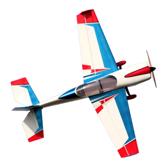
Manual – Extra NG – 67"
1- Introduction:
WELCOME TO THE PILOT-RC TEAM!
Thank you for choosing a Pilot-Rc plane as your next model. We hope that you
enjoy many successful and exhilarating flights with your new plane. Please read
through these instructions before you start building or flying to assure a successful
experience, and welcome to Team Pilot-Rc!
YOUR MODEL:
Model:
Wingspan:
Length:
Wing area:
Extra NG
67" (1.702mm)
65.4" (1.661mm)
872 "² (5,632 cm²)
Advertisement

Related Manuals for Pilot RC Extra NG - 67


Summary of Contents for Pilot RC Extra NG - 67
- Page 1 Manual – Extra NG – 67″ 1- Introduction: WELCOME TO THE PILOT-RC TEAM! Thank you for choosing a Pilot-Rc plane as your next model. We hope that you enjoy many successful and exhilarating flights with your new plane. Please read through these instructions before you start building or flying to assure a successful experience, and welcome to Team Pilot-Rc! YOUR MODEL:...
-
Page 2: Included Hardware
Weight: 8.1lbs (3.7kg) INCLUDED HARDWARE: Complete air frame with all basic accessories (such as carbon fibre main • undercarriage, tail-gear assembly and wing-tubes as well as fibreglass control horns and wheel pants) Included wing bags • Included extension wires • Pre-prepared hinges ready to be installed and pre-mounted canopy •... - Page 3 Epoxy Adhesives • Cyanocrylate adhesives • X-Acto and Saw knives • Sandpaper • Thread lock • Aircraft stand or support • Drill, screw drivers, allen keys, wrench set, pliers, etc • 2- DISCLAIMER All Pilot-RC products are guaranteed against defects for 30 days of your receiving the model.
-
Page 4: Main Landing Gear Assembly
Seek the assistant of local model flying clubs and or an experienced aeromodeller for assembly, operation and maintenance to ensure a quick and successful learning process. Fly only at designated model flying fields approved by the AMA (Academy of Model Aeronautics), the MAAC (Model Aeronautic Association of Canada) or the similar corresponding governing body for your country. - Page 5 • •...
- Page 6 • • Screw the wheel axles on to the landing gear, and then slide on the wheels and secure in place with the provided grub screws.
-
Page 7: Tail Wheel Installation
Position the fuselage upside down and screw on the carbon undercarriage to the fuselage using the nuts and bolts provided. Some users may prefer to leave the wheels until the end of the build, to prevent the model moving on the build table. TAIL WHEEL INSTALLATION: •... - Page 8 • • With the model still upside down, position the carbon tail wheel unit on its correct location and mark on the underside of the fuselage to drill the holes for the screws that will hold the tail wheel in place.
-
Page 9: Stabiliser Installation
Attach the ball link to the underside of the rudder using a small amount of Epoxy. Run the control rod through the above ball link and screw the tail wheel unit to the fuselage using the wood screws provided. We recommend to keep the pivot point of the tail wheel as in line with the hinge line as possible to assure a bind free movement of the springs. - Page 10 • •...
- Page 11 • •...
- Page 12 • Cut free the trailing edge of the vertical rudder in line with the stabiliser, in order to allow you to slide the stabiliser into the fuselage. Keep the removed section for later. Trial fit the stabiliser into the fuselage. Make sure that it is centered (measure the tip of the stabiliser to the tip of the wing on both sides and make sure they are the same distance) and correctly aligned (looking at wings and stabiliser, should show all being parallel)
- Page 13 • • It is very important to sand horn to assure a strong bond once glued to the model.
- Page 14 Locate and cut the covering where the horns will be glued Glue them to the surface using epoxy glue Excess epoxy glue can be removed with acetone INSTALLING THE SERVO HORN ON THE RUDDER: • It is very important to sand horn to assure a strong bond once glued to the model. Locate and cut the covering where the horns will be glued Glue them to the surface using epoxy glue Excess epoxy glue can be removed with acetone...
- Page 15 • • It is very important to sand horn to assure a strong bond once glued to the model.
-
Page 16: Aileron Servo Installation
Locate and cut the covering where the horns will be glued Glue them to the surface using epoxy glue Excess epoxy glue can be removed with acetone AILERON SERVO INSTALLATION: •... - Page 17 • •...
- Page 18 • •...
-
Page 19: Rudder Servo Installation
• Install and glue the included hinges. Locate and cut the covering where the servos will be installed. Route the servo wire through the wing and screw the servo in place. Centre the servo with your transmitter, attach the servo arm and connect the servo to the ailerons with the pushrods provided. -
Page 20: Elevator Servo Installation
• Install and glue the included hinges. Locate and cut the covering where the servo will be installed, at the rear of the fuselage, under the elevator. Route the servo wire through the wing and screw the servo in place. Centre the servo with your transmitter, attach the servo arm and connect the servo to the ailerons with the pushrods provided. - Page 21 • •...
- Page 22 • Install and glue the included hinges. Locate and cut the covering where the servo will be installed, at the rear of the fuselage, under the elevator. Route the servo wire through the wing and screw the servo in place. Centre the servo with your transmitter, attach the servo arm and connect the servo to the ailerons with the pushrods provided.
- Page 23 • •...
- Page 24 •...
- Page 25 •...
- Page 26 • First, locate the secondary firewall box that acts as a standoff for the electric motor. Attach it to the main firewall using the provided bolts and blind nuts.l Follow the laser diagram on the firewall to drill the necessary holes for the motor.
- Page 27 • •...
- Page 28 •...
- Page 29 •...
- Page 30 • •...
- Page 31 Attach the the plastic motor mount to the fuselage, use the mounting screws to secure in place. Position the engine onto the plastic motor mount beams and check the required space between the engine cowl and the motor hub. Once the correct separation has been determined, permanently fix the motor to the plastic motor mount beams.
- Page 32 •...
-
Page 33: Cowling Installation
• • Please note it is important to install the triangular reinforcement for the front former, this helps assure correct alignment between the canopy and the cowl. This applies both to electric and gas setups! COWLING INSTALLATION:... - Page 34 •...
- Page 35 • •...
- Page 36 • The cowling is installed using four screws that go into four “tabs” in the fuselage. The exact location of the cowling can be adjusted slightly to allow an easy fit of whichever your chosen motor is (longer or shorter) In order to assure drilling in the correct location, with the cowl off, place some small strips of masking tape in line with the four tabs where we want the cowling screws to go.
- Page 37 • • Check the correct location of your chosen battery depending on your CG.
- Page 38 Glue the Velcro strip to the battery tray (and battery), as well as threading a velcro strap round the battery tray, assuring a completely secure battery once fully installed. Finally install your receiver with double sided tape or velcro, making sure that all servo leads can be easily connected without being too tight, and that the receiver is securely fixed in place.
- Page 39 • Slide the wheel pants over the wheels and axles, supporting the rear of the pants to line up with the ground and mark where to drill the two screw holes in the wheel pants. Remove the wheel pants and drill the holes for the appropriate holes. Before putting back on the plane, mount the bolt with the blind nut on the wheel pant and tighten until the nut sits flush with the wheel pant.
- Page 40 • •...
- Page 41 • BALANCING THE CG OF AIRPLANE: The CG is marked inside the fuselage, near the wing tube. Install the included balance rods in their position, attach the canopy and check the balance of the model. Move your batteries accordingly until correctly balanced. Personal CG preference can be adjusted following the first flight.
- Page 42 Surface Deflection Ailerons: 38º Elevators: 55º Rudder: 45º DOUBLE CHECK: Double check that all screws are installed, all components tightly secured, batteries and or fuel tank are full, all surfaces are working in the correct directions, balance is correct and range test passed before performing your maiden flight. WE WISH YOU A SUCCESFUL MAIDEN AND MANY HAPPY FLIGHTS WITH YOUR NEW MODEL.
Need help?
Do you have a question about the Extra NG - 67 and is the answer not in the manual?
Questions and answers