
Subscribe to Our Youtube Channel
Related Manuals for Pentair 1532C Series


Summary of Contents for Pentair 1532C Series
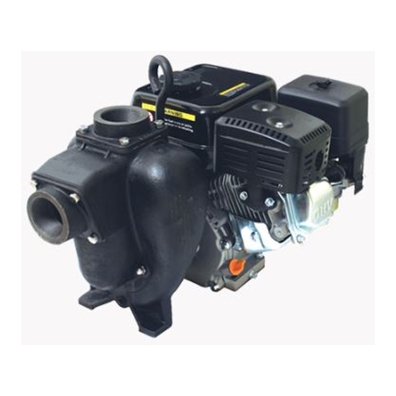
- Page 1 SELF PRIMING CAST IRON CENTRIFUGAL PUMPS 1532C DIESEL FUEL TRANSFER PUMP SERIES OWNER'S MANUAL pentair.com ©2023 Pentair. All Rights Reserved.
-
Page 2: Table Of Contents
TABLE OF CONTENTS SAFETY INFORMATION . . . . . . . . . . . . . . . . . . . . . . . . . . . . . . . . . . . . . . . . . . . . . . . . . . . . . . . . . . . . . . . . . . . . . . . . . . . . . . . . . . . . . . . . . . . . . . . . . . . 3 INSTALLATION &... -
Page 3: Safety Information
SAFETY INFORMATION SAFETY SYMBOLS Secure the discharge lines before starting the pump. An This is the safety alert symbol. When you see this symbol on unsecured line may whip, causing personal injury and/or your pump or in this manual, look for one of the following signal property damage. -
Page 4: Installation & Operation
INSTALLATION & OPERATION INSTALLATION DISCHARGE CONNECTIONS Your pump is equipped with a single port discharge. Select the PRELIMINARY TO MOUNTING appropriate size for the application. Install a “T” to allow easy Before setting up the pump for operation, check to see that priming of the pump without disconnecting the piping, or by the motor and pump turn freely by hand. - Page 5 INSTALLATION & OPERATION Remove the fill cap/dipstick. Add oil until the level reaches Choke: When starting a cold engine, move the choke the bottom of the opening. control to the left (closed). As the engine warms up, move it towards the right (open). A warm engine should start with Check the oil level by pushing the cleaned dipstick into the the choke open.
- Page 6 INSTALLATION & OPERATION PUMP ASSEMBLY / DISASSEMBLY Remove impeller, drive sleeve, mechanical seal assembly. Insert a shim between the impeller vanes and pump INITIAL ASSEMBLY: GAS ENGINE OR PEDESTAL MOUNT wear plate. A shim 1/2” wide and 0.040” to 0.050” thick is Prior to assembly, visually inspect pump outlet for impeller required.
- Page 7 INSTALLATION & OPERATION / MAINTENANCE Remove impeller, drive sleeve, mechanical seal assembly. Remove cork gasket and discard. Remove any gasket residue from adapter and pump faces. SERVICE INSTRUCTIONS Inspect wear plate for excessive wear, surface grooves or impeller contact. Replace if needed. Figure 6 Remove two 3/8”...
-
Page 8: Maintenance
MAINTENANCE MECHANICAL SEAL ENGINE MAINTENANCE AIR FILTER Remove seal and spring from impeller/drive sleeve assembly (Figure 11). The air filter should be checked every month for dust and dirt accumulation. Every 6 months, the filter element should be removed and cleaned. Clean the foam element with detergent and warm water. -
Page 9: Performance & Specifications
SPECIFICATIONS & PERFORMANCE SPECIFICATIONS Max Flow Rate: ............170 GPM Max . -
Page 10: Troubleshooting
TROUBLESHOOTING PROBABLE CAUSE SYMPTOM ENGINE PUMP SYSTEM No fluid delivered Not enough fluid delivered Not enough pressure Engine heats excessively Abnormal noise and/or vibration Pump works for a while, then stops PROBLEM POSSIBLE CAUSE(S) ENGINE Refer to engine section . A. -
Page 11: Parts List
PARTS LIST Repair Kit 3430-0775 contains: (1) ref. # 4 flapper, (1) ref. # 6 gasket, (1) ref. # 14 mechanical seal, and (1) ref. # 15 gasket. Qty. Part No. Description Qty. Part No. Description 2210-0160 Cap Screw, 5/16-18 0501-9032 Shaft Sleeve (3/4”) 2260-0051... - Page 12 Fx: 800.323.6496 All indicated Pentair trademarks and logos are property of Pentair. Third party registered and unregistered trademarks and logos are the property of their respective owners. Because we are continuously improving our products and services, Pentair reserves the right to change specifications without prior notice. Pentair is an equal opportunity employer.
Need help?
Do you have a question about the 1532C Series and is the answer not in the manual?
Questions and answers