
Related Manuals for Resodyn OmniRAM


Summary of Contents for Resodyn OmniRAM
- Page 1 Omni ® Installation Manual Resodyn Acoustic Mixers 130 N. Main Street, Butte, MT 406-497-5333 Info@resodynmixers.com 022823...
-
Page 2: Table Of Contents
5.0 RAM Basics ........................5-1 Operating the OmniRAM ....................5-1 LIST OF FIGURES Figure 3-1: OmniRAM Mixer, Rear View, Hood Closed ............3-1 Figure 3-2: OmniRAM Mixer, Right-Side View................. 3-1 Figure 3-3: Required Clear Areas Around OmniRAM .............. 3-2 Figure 4-1: OmniRAM Hoist Attachment ................4-14 Figure 4-2: ACE Bolt Locations ..................... -
Page 3: Installation Manual Revision Management
Periodically, as required, this document will be updated to correct errors and document any additional features. Table 1-1 documents the revision, changes, and release date. Table 1-1: Manual Revision History Revision Description Date Initial Release 02/01/2023 Resodyn Acoustic Mixers 130 N. Main Street, Butte, MT 406-497-5333 Info@resodynmixers.com... -
Page 4: Safety
Safety 2.0 SAFETY Every effort has been made to ensure that the OmniRAM is easy to use, reliable, and safe. This section outlines the general safety considerations and defines caution and warning symbols used throughout this manual. For safe operation, the OmniRAM must be operated only within the limits outlined in the system specifications. -
Page 5: Component Replacement
OmniRAM Installation Manual Safety Component Replacement The OmniRAM is designed with components that are specifically rated for use with the OmniRAM machine. Replace worn, or damaged, components only with direct factory replacement parts, or parts approved by Resodyn Acoustic Mixers. Incorrect component replacement can impair the safety of the equipment and risk injury to personnel. -
Page 6: System Installation Overview
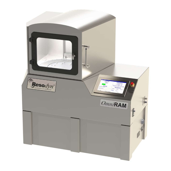
The OmniRAM is a ResonantAcoustic Mixer for use in industrial mixing and processing applications. The OmniRAM consists of a main enclosure that includes a sliding hood, access panels, and Human-Machine Interface (HMI) (see Figure 3-1 and Figure 3-2). Optional subsystems that attach to the enclosure include the Hoist, Vacuum Module, and Commented [TF1]: I reworded this sentence for clarity;... - Page 7 The OmniRAM enclosure requires clear areas around the machine that are necessary for hookups, maintenance, and machine usability. Components and relative location (including clear areas and connections of the OmniRAM) are depicted in Figure 3-3 and Resodyn Acoustic Mixers 130 N. Main Street, Butte, MT 406-497-5333...
- Page 8 OmniRAM Installation Manual System Installation Overview Table 3-1. Clear areas around the OmniRAM (identified in Figure 3-3) are required to meet operational, safety, and maintenance needs. Deviation from clear areas may compromise the safety of operating personnel and may cause downtime and equipment damage.
- Page 9 11 Vessel Vacuum Supply Hose Customer-supplied plumbing 12 Optional Vacuum Exhaust Hose Customer-supplied plumbing 13 Optional Vessel Bleed Exhaust Hose Customer-supplied plumbing 14 Vacuum Controller Compressed Air Supply Customer-supplied plumbing Resodyn Acoustic Mixers 130 N. Main Street, Butte, MT 406-497-5333 Info@resodynmixers.com...
-
Page 10: Specifications
Machine parameter display and control Recipe definition and control Manual mix timer Setup and configuration screens for supervisors and administrators Interlocked Acoustic Enclosure Panels Cooling System control monitoring Resodyn Acoustic Mixers 130 N. Main Street, Butte, MT 406-497-5333 Info@resodynmixers.com... - Page 11 Alarm display and logging: Log file records, triggered time, recovered time, and acknowledged time User management: Multiple operator users User must be logged in to operate the OmniRAM Log file tracks login attempts Auxiliary Communications Enclosure Material: Stainless-steel; IP 40 Rated enclosure Dimensions: 12 in [305 mm] H ×...
-
Page 12: Installation
Prior to installation, ensure the facility is prepped and ready for the OmniRAM and all external components. Contact Resodyn (see Table 2-2) if an installation team, or offsite support, is needed to work with the customer’s facility team during the installation process. - Page 13 Disconnect the four (4) connections to the Amplifier Module. Pushing up on the tab, disconnect the two (2) I/O connections. Then, disconnect the coolant and return quick-connects (red hoses). Resodyn Acoustic Mixers 130 N. Main Street, Butte, MT 406-497-5333 Info@resodynmixers.com...
- Page 14 5/8” front- to-back, and 3/4” side-to-side. Commented [TF2]: Hand-tighten? Or is a tool needed? When complete, tighten the bolt to lock the leveling feet. Resodyn Acoustic Mixers 130 N. Main Street, Butte, MT 406-497-5333 Info@resodynmixers.com...
- Page 15 Mix Process Control Module. Reach through the opening to behind lower access panel, disconnect the one (1) I/O connection. Finally, disconnect the two (2) Coolant quick-connects (red hoses). Resodyn Acoustic Mixers 130 N. Main Street, Butte, MT 406-497-5333 Info@resodynmixers.com 4-10...
- Page 16 Step 13: Using a 5/16” Allen wrench, adjust the leveling foot to raise the caster off the floor. Resodyn Acoustic Mixers 130 N. Main Street, Butte, MT 406-497-5333 Info@resodynmixers.com 4-11...
- Page 17 Tighten the locking nuts after Commented [TF3]: With a tool or hand-tighten? leveling machine. Resodyn Acoustic Mixers 130 N. Main Street, Butte, MT 406-497-5333 Info@resodynmixers.com 4-12...
- Page 18 (1) I/O connection, and the two (2) coolant quick-connects (red hoses). Step 19: Slide the Amplifier Module back into place. Secure by reinstalling the two (2) wing nuts. Resodyn Acoustic Mixers 130 N. Main Street, Butte, MT 406-497-5333 Info@resodynmixers.com 4-13...
- Page 19 Module by connecting the two (2) I/O connections and the two (2) coolant quick-connects (red hoses). Step 21: Using a 5/16” Allen wrench and a half-turn, reinstall the Lower Enclosure Access Panel. Resodyn Acoustic Mixers 130 N. Main Street, Butte, MT 406-497-5333 Info@resodynmixers.com 4-14...
-
Page 20: Installing The Hoist (Optional Accessory Skip Section 4.4 If Not Purchased.)
4-1) that ships separately from the machine. The installation instructions outline the steps to mount the Hoist on the OmniRAM, and apply to both the Manual and Pneumatic Hoists. Additional installation steps specific to Pneumatic installation are addressed in Section Commented [TF5]: 4.4.2. - Page 21 Step 3: Install the bolt access caps. Push the six (6) caps into place to cover the bolt access holes in the Hoist beam. Resodyn Acoustic Mixers 130 N. Main Street, Butte, MT 406-497-5333 Info@resodynmixers.com 4-16...
- Page 22 OmniRAM Installation Manual Installation Step 4: Attach the Hoist to the eyebolt on the Hoist frame. Step 5: Attach the lifting sling to the Hoist. Resodyn Acoustic Mixers 130 N. Main Street, Butte, MT 406-497-5333 Info@resodynmixers.com 4-17...
- Page 23 Use the three-foot [91 cm] hose to connect the Hoist to the elbow on the upper portion of the Hoist Vertical Member. Apply Teflon tape to both ends of the hose before installing. Resodyn Acoustic Mixers 130 N. Main Street, Butte, MT 406-497-5333 Info@resodynmixers.com 4-18...
- Page 24 Apply Teflon tape to both ends of the hose before installing. Remove the plug, if necessary. Connect the client-provided Pneumatic Air Line 1/2” (Female NPT Connection) to the Lower Hoist Air Connection. Resodyn Acoustic Mixers 130 N. Main Street, Butte, MT 406-497-5333 Info@resodynmixers.com 4-19...
-
Page 25: Mounting The Auxiliary Communications Enclosure (Ace)
The customer is responsible for ensuring the ACE is mounted in such a way that it complies with all company, local, and national regulations. Figure 4-2: ACE Bolt Locations Resodyn Acoustic Mixers 130 N. Main Street, Butte, MT 406-497-5333 Info@resodynmixers.com 4-20... - Page 26 Secure the ACE in place using 3/8” [10 mm] or larger diameter bolts, or the customer-supplied hardware required by company, local, and national regulations. Resodyn Acoustic Mixers 130 N. Main Street, Butte, MT 406-497-5333 Info@resodynmixers.com 4-21...
-
Page 27: Connect Machine Chilling System
Machine chilling is required for proper temperature control of the enclosure. Liquid cooling hookups are located on the enclosure and a Machine Chiller is recommended. The steps below outline hooking up with the Resodyn Machine Chiller. Specifications are outlined in Table 4-2. - Page 28 See the machine Chiller Manual for additional information. NOTE: Step 2: Connect the facility water inlet and outlet lines located on the back of the Chiller. NOTE: See the machine Chiller Manual for additional information. Resodyn Acoustic Mixers 130 N. Main Street, Butte, MT 406-497-5333 Info@resodynmixers.com 4-23...
- Page 29 Step 5: Using the supplied DB9 cable, connect the Chiller communication line on the back of the Chiller to the Chiller 1 port on the Auxiliary Communication Enclosure. Resodyn Acoustic Mixers 130 N. Main Street, Butte, MT 406-497-5333 Info@resodynmixers.com 4-24...
-
Page 30: Connect Process Heater/Chiller And Process Module (Optional Items)
The Process Heater/Chiller and Process Module are optional upgrades that permit Jacketed Vessel heating and cooling during mix processing. Temperature-control hookups are located on the enclosure, and the Resodyn Process Heater/Chiller is recommended for seamless interfacing with the system mix processing. The steps below outline Heater/Chiller installation and hookup to the OmniRAM enclosure. - Page 31 Heater/Chiller to the Chiller 2 port on the Auxiliary Communication Enclosure. NOTE: If only one Chiller was purchased, it connects to the Chiller 1 port. Resodyn Acoustic Mixers 130 N. Main Street, Butte, MT 406-497-5333 Info@resodynmixers.com 4-26...
-
Page 32: Connect Vacuum Module (Optional System)
Connect Vacuum Module (Optional System) The Vacuum Module is an optional system used to pull vacuum on Vessels as part of the mix process. The Vacuum Module comes installed in the OmniRAM and can be accessed from the back of the machine. -
Page 33: Vacuum Pump And Starter Box (Optional System)
The customer is responsible for ensuring the Starter Box is mounted in such a way that it complies with all company, local, and national regulations. Figure 4-3: Vacuum Pump Starter Box Enclosure Bolt Locations Resodyn Acoustic Mixers 130 N. Main Street, Butte, MT 406-497-5333 Info@resodynmixers.com 4-28... - Page 34 Step 4: Connect the Vacuum Pump power supply and power lines to the Starter Box. NOTE: A hole will need to be drilled to route wiring Resodyn Acoustic Mixers 130 N. Main Street, Butte, MT 406-497-5333 Info@resodynmixers.com 4-29...
-
Page 35: Removing The Shipping Bracket
Apply Loctite 243 to the threads of each bolt. Using a 9/16” wrench, torque the bolts to 88 in-lbf [9.9 Nm]. Resodyn Acoustic Mixers 130 N. Main Street, Butte, MT 406-497-5333 Info@resodynmixers.com 4-30... -
Page 36: Connect Facility Air To The Omniram
Do NOT operate the OmniRAM with the shipping bracket still installed. Doing so may damage the machine. Connect Facility Air to the OmniRAM The Standard OmniRAM requires clean dry facility air inside the machine to manage condensation. Step 1: Connect facility air to the OmniRAM. - Page 37 Route the input power line. Input power is: • 1-phase • 220 - 240 VAC • 40 A • 50/60 Hz Resodyn Acoustic Mixers 130 N. Main Street, Butte, MT 406-497-5333 Info@resodynmixers.com 4-32...
- Page 38 NOTE: For additional information see electrical Schematic 905170-XX. Figure 4-4: Facility Power Connection Step 7: Slide the Amplifier Module back into place and secure with the two (2) wing nuts. Resodyn Acoustic Mixers 130 N. Main Street, Butte, MT 406-497-5333 Info@resodynmixers.com 4-33...
- Page 39 Reconnect the four (4) connections to the Amplifier Module by connect the two (2) I/O connections and the two (2) coolant quick-connects (red hoses). Step 9: Using a 5/16” Allen wrench and a half- turn, reinstall the Lower Enclosure Access Panel. Resodyn Acoustic Mixers 130 N. Main Street, Butte, MT 406-497-5333 Info@resodynmixers.com 4-34...
-
Page 40: Ram Basics
• The ability to process materials not possible by other methods. Operating the OmniRAM This installation document is NOT a user manual, See the OmniRAM User Manual for detailed operating instructions. It is the customer’s responsibility to ensure all operators receive the correct training and have read and understand the User Manual before operating the equipment. - Page 41 Resodyn Acoustic Mixers 130 N. Main Street, Butte, MT 406-497-5333 Info@resodynmixers.com 022823...
Need help?
Do you have a question about the OmniRAM and is the answer not in the manual?
Questions and answers