
Related Manuals for Resodyn LabRAM I


Summary of Contents for Resodyn LabRAM I
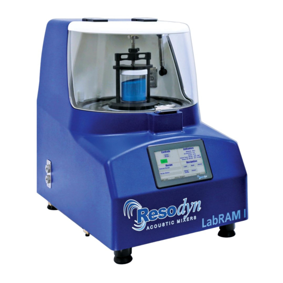
- Page 1 LabRAM I Installation and User Manual Resodyn Acoustic Mixers 130 N. Main Street Butte, MT, 59701 USA +1-406-497-5333 ResodynMixers.com...
-
Page 2: Table Of Contents
Handling/Lifting ......................7 ® ResonantAcoustic Mixing (RAM) Basics ............... 8 Definitions ........................10 Installation ........................11 Unpacking, Lifting, and Placing LabRAM I ..............11 Using the Retractable Handles..................12 Mounting ........................12 Lid Operation ......................13 Remove the Shipping Lock Bar ...................14 Install Vessel Holder Assembly ...................15 Electrical Connections ....................17... - Page 3 LabRAM I Installation and User Manual Run the Recipe ......................26 Completion .........................27 HMI (Human Machine Interface) – Overview ..............28 Main Screen........................28 Login ...........................29 Operational Modes (Recipe and Auto) ................29 Alarming ........................29 Setup and Configuration Screens ................29 Viewer .........................30 Detailed HMI Operation – Security and Login ..............30 10.1...
-
Page 4: Revision History
LabRAM I Installation and User Manual 15.2 Cleaning Procedures ....................62 15.3 Accelerometer Calibration ...................62 15.4 Maintenance .......................62 15.4.1 Major Repairs ....................62 15.4.2 Recommended Maintenance Schedule ............63 15.5 Replacement of Serviceable Parts ................63 15.5.1 Fuse Replacement ...................63 15.5.2 Bellows Replacement ..................64 15.5.3 Accelerometer Replacement ................64... -
Page 5: Safety
LabRAM I Installation and User Manual Safety 1 Safety Every effort has been made to assure that the LabRAM I is easy to use, reliable, and safe. This section outlines the general safety considerations and defines caution and warning symbols used throughout this manual. -
Page 6: Important Safety Notes
The LabRAM I system is designed with components that are specifically rated for use with the LabRAM I machine. Replace worn or damaged components only with factory-replacement parts or parts approved by Resodyn Acoustic Mixers. -
Page 7: Guards And Safety Devices
(Figures 1 and 2 below). Two remaining personnel can assist in lifting the LabRAM I mixer at the front and back base plate next to the machine feet. Exercise caution when lifting and moving the LabRAM I to avoid striking other objects. -
Page 8: Resonantacoustic Mixing (Ram) Basics
ResonantAcoustic Mixing (RAM) is an advanced mixing and processing technology that utilizes low-frequency acoustic energy. The LabRAM I is an innovative approach to multiple mixing applications from an initial pilot stage to production scale. These applications include powder- powder systems, powder-liquid systems, liquid-gas systems, as well as combinations thereof. - Page 9 This means that a finding of optimal settings on the bench scale LabRAM I or LabRAM II mixer will be nominally equivalent to settings on the OmniRAM, RAM 5, or RAM 55 mixers to process the same materials. As such, transitioning from discoveries made in the laboratory to the pilot or production scale is seamless for most processes.
-
Page 10: Definitions
LabRAM I Installation and User Manual Definitions 3 Definitions A change in velocity with respect to time that is expressed in “g.” Different Acceleration: materials mix at different accelerations, based on the material properties and other factors. (See “g” below.) -
Page 11: Installation
Section 1.8 Handling/Lifting on the previous page. Upon receipt of the LabRAM I, do not unpack or remove any packaging materials until the carton has been positioned as close to the installation location as possible. When in position, remove all wrapping and strapping, and file shipping paperwork for your records. -
Page 12: Using The Retractable Handles
Installation 4.2 Using the Retractable Handles Retractable handles are located on both sides of the LabRAM I, installed in the base plate and conveniently out of the way when not in use. When you are prepared to lift and place the machine: 1. -
Page 13: Lid Operation
NOTE: The lid is equipped with a Safety Interlock Switch. If the lid is not fully secured, the LabRAM I will not operate. If the lid is opened while mixing, the mixer will stop. Do not attempt to override the Safety Interlock Switch as serious injury may result. -
Page 14: Remove The Shipping Lock Bar
LabRAM I Installation and User Manual Installation 4.5 Remove the Shipping Lock Bar The LabRAM I is shipped with a Lock Bar that secures the resonator during transportation. The Lock Bar must be removed before proceeding with installation or attempting to operate the LabRAM I. -
Page 15: Install Vessel Holder Assembly
When fully-seated, torque each cap screw to 8 ft-lb (10.8 Nm) using a 3/16” Hex Wrench tool. On its highest setting, the LabRAM I mixer payload operates at 100 g of acceleration. The vessel holder screws must be torqued to 8 ft-lb (10.8 Nm) to prevent the Vessel Holder and Vessel from loosening during operation. - Page 16 LabRAM I Installation and User Manual Installation All Vessel Holder assemblies will match a hole pattern in the Top Plate of the LabRAM I. The mounting hole pattern for the standard 4” Vessel Holder is ¼-20 threads measuring 4.375” (111.13 mm) center-to-center. See the detailed illustration below for the position of these mounting holes.
-
Page 17: Electrical Connections
5 Technical Support Every effort is made to ensure your LabRAM I is intuitive to use, and that it provides a long life of reliable operation. If you have questions about its operation, or if your LabRAM I appears to be malfunctioning, please do not hesitate to contact Resodyn Acoustic Mixers. -
Page 18: System Specifications
Mini USB • Communication Connector for Automatic Vacuum System All external connections are found in the back panel of the LabRAM I machine. See Figure 6 on Page 17 for a detailed illustration. Table 6-1. LabRAM I System Specification. Maximum Payload Capacity 1.1 lb (500 gram) -
Page 19: System Overview
Communication Connections Figure 8 LabRAM I External Features The LabRAM I delivers energy to the material being mixed by moving the mixing vessel up and down, 60 times a second, at up to 100 g of acceleration. Resodyn Acoustic Mixers... -
Page 20: Acoustic Enclosure
Figure 9 LabRAM I Acoustic Enclosure 7.1 Touch Screen Human Machine Interface (HMI) The LabRAM I is digitally controlled through the HMI. All data entry and operations are provided through software keypads and buttons on the screen. The touch screen and operating system are described in detail in Section 9 HMI (Human Machine Interface) –... -
Page 21: Standard Vessel Holder Fixture And Vessels
A variety of vessel sizes and types, along with appropriate Vessel Holder fixtures, are available for the LabRAM I. The standard and supplied Vessel Holder is 4” (101.6 mm) in diameter and accommodates Mixing Vessels between 3.25” and 4.6” high (82.55 mm and 116.84 mm). -
Page 22: Processing Accessories
• RTD Temperature Monitoring – Mixing ingredient temperature is monitored by the LabRAM I HMI via an RTD sensor installed in a vacuum system lid. The LabRAM I has an RTD communications connector directly behind the vessel holder. Interior Vacuum... -
Page 23: Recipe Demonstration Quick Start
Recipe Demonstration Quick Start Recipe Demonstration Quick Start This section defines the minimum steps required to operate the LabRAM I. All instructions and guidelines in Section 4 Installation must be completed before attempting a Quick Start or operation of the LabRAM I. -
Page 24: Power-Up
Logo Boot-Up Screen: Power Applied 8.3 Login Before running the LabRAM I, a user login is required. For the example, the lowest, or most restricted, level login will be used. Both the username and password are “operator.” 1. Touch the <Login/Logout> button. -
Page 25: Select The Recipe
Recipe Demonstration Quick Start 8.4 Select the Recipe The LabRAM I is provided with a demonstration recipe to use as a reference and guideline. The following steps illustrate how to select and use that demonstration recipe. 1. Touch the <Select Recipe> button. The “Select Recipe” screen is displayed. -
Page 26: Run The Recipe
LabRAM I Installation and User Manual Recipe Demonstration Quick Start 5. The Main Screen will display the name of the selected recipe in the “Recipe” pane, and the green <Start Mixer> button will also appear. 8.5 Run the Recipe A recipe is a pre-defined, sequenced processing routine that runs the mixer at specific acceleration, vacuum, and temperature settings for defined periods of time. -
Page 27: Completion
LabRAM I Installation and User Manual Recipe Demonstration Quick Start 8.6 Completion When the middle section of the Recipe Status Bar (See Section 9.1 Main Screen for Status Bar location) reads “Status: Ready,” the mixer’s Lid can be opened, and the Mixing Vessel can be removed. -
Page 28: Hmi (Human Machine Interface) - Overview
HMI Operation – Modes of Operation 9 HMI (Human Machine Interface) – Overview The HMI is a digitally-controlled user interface on the LabRAM I. All data entry and operations are provided through software keypads and buttons on the HMI screen. -
Page 29: Login
To operate the LabRAM I, user authentication (login) is required. Four different login privilege levels are provided to control access to machine features. The LabRAM I is pre-configured with the default “users” names and passwords at each level of login. These logins are tabulated below. -
Page 30: Viewer
10 Detailed HMI Operation – Security and Login To protect the LabRAM I from unauthorized use, and to maintain a record of which users operated the mixer, the system incorporates a user authentication system. Users are required to enter a username and password before operating the mixer. -
Page 31: Screen Operations - Logging In/Out
LabRAM I Installation and User Manual HMI Operation – Modes of Operation 10.2 Screen Operations - Logging In/Out The following sequence outlines the steps for logging in using the pre-configured supervisor login. Touch the <Login/Logout> button The “Login” screen will appear. Touch the textbox beneath “Username:”... -
Page 32: Log Files
Touch <OK> to try again 10.3 Log Files Every login attempt, successful or not, is logged to data files in the LabRAM I’s memory. These files can be uploaded to a PC via USB for data archiving. See Section 14.8 Data Tab. -
Page 33: Hmi Operation - Modes Of Operation
11 HMI Operation – Modes of Operation As previously noted, the LabRAM I is controlled in one of two operating modes: Auto Mode and Recipe Mode. Recipe Mode is the primary mode used by operators, while Auto Mode is used by higher levels to characterize a mixing process for eventual recipe programming. - Page 34 60g. and 0torr, respectively. When the timer of the final segment expires, the The LabRAM I can be stopped by touching the mixer will stop. The <Stop Mixer> button changes <Stop Mixer> button during a recipe mix. Normally, to the <Start Mixer>...
- Page 35 <Start Mixer> button. 11. The LabRAM I will give the option of starting from the beginning of the recipe, by touching the <Start Over> button, or continuing from the point the mixer was stopped, by touching the <Resume> button.
-
Page 36: Screen Operations - Auto Mode
HMI Operation – Modes of Operation 11.2 Screen Operations - Auto Mode The following details the steps for operating the LabRAM I in Auto Mode. Note that this sequence assumes the user has already logged in to the system with authorized login credentials to operate in Auto Mode. - Page 37 “Acceleration Control” dialog. a Configuration, touch the <Config/Alarms> button. NOTE: If the LabRAM I is mixing or in acceleration, the setpoint will be used as soon as a valid setpoint was entered. The LabRAM I does not wait for you to touch <Done>.
- Page 38 LabRAM I Installation and User Manual HMI Operation – Modes of Operation The “Auto Mode Configuration and Alarms” screen 10. The “Select Configuration” dialog will appear, and is displayed and allows a user to define limits to the Configuration can be selected from the list (only setpoint entry or shut the machine down if one configuration is defined in the image).
- Page 39 LabRAM I will begin accelerating/mixing. The text entered in this screen is stored in a log file in <Start Mixer> button changes to the <Stop Mixer> the LabRAM I’s memory. Touch <OK> when button. Depending on Auto Mode Timer mode finished.
- Page 40 LabRAM I Installation and User Manual HMI Operation – Modes of Operation 20. When the timer 19. When the timer is running the <Reset> button will expires, be disabled. Timer duration cannot be changed LabRAM I when the timer is running. Pressing the will stop accelerating/mixing.
-
Page 41: Hmi Operation - Alarms
HMI Operation – Viewer 12 HMI Operation – Alarms The LabRAM I protects the user and itself by monitoring parameters that could cause injury or damage. An alarm is triggered when any of these parameters are violated. The user is notified in the Alarm Section of the Main Screen Status Bar by a change in color to either red or yellow. -
Page 42: Hmi Operation - Viewer
13 HMI Operation – Viewer The LabRAM I measures several parameters important to mixing efficiency. These measured parameters can be viewed in real-time as time-history plots. To view real-time plots, touch the <Viewer> button in the Navigation Pane of the Main Screen. - Page 43 LabRAM I Installation and User Manual HMI Operation – Viewer The smaller “power(%)” can now be examined The visible plots will now have a shorter overall time and will be “zoomed in.” Touching the more closely. To focus on a specific parameter of <Zoom ->...
-
Page 44: Hmi Operation - Setup And Configuration
The LabRAM I offers the user extensive customization and flexibility. The Setup and Configuration screen provides user control of optional features and manages the configuration of the LabRAM I. The Setup and Configuration screen is accessed by touching the <Setup/Config> button from the Main Screen. -
Page 45: Status Tab
14.3 Recipe Tab The Recipe Tab is used to create and edit recipes and recipe groups. The LabRAM I has the capability to store 10 recipe groups with 10 recipes per group for a total of 100 recipes. Recipe groups can be thought of “folders,”... - Page 46 Only the <New Group> button is enabled on the left because no recipe group has been selected. The recipe contents will be read from the LabRAM I’s memory After touching the recipe name, an arrow will appear indicating and displayed on the screen shown above. The recipe name that the recipe has been selected.
- Page 47 The “Acceleration Recipe Entry” dialog will appear. Use this control on the right-side. Temperature and vacuum setpoints can be entered in the same fashion, if the LabRAM I is dialog entry the same as the Auto Mode acceleration entry. Touch the textbox and enter 51 using the “Numeric Entry”...
- Page 48 LabRAM I Installation and User Manual HMI Operation – Setup and Configuration 10. To add another segment between existing segments in the A new segment, segment 4, is now added to the end of this recipe, the <Insert> button will be used this time.
-
Page 49: Screen Operations - Create New, Rename, And Delete
LabRAM I Installation and User Manual HMI Operation – Setup and Configuration This concludes the “edit Recipe portion of Screen Operations – Edit an Section 14.3.1 Existing Recipe. The following section continues to assume Log In as a Supervisor. 15. A confirmation dialog will appear. Touch <Yes> to save. - Page 50 Configuration” dialog as seen in step 5. The “Type:” textbox is used for selecting the segment type. NOTE: Currently Time segments are the only option. This feature will be expanded in future firmware revisions or the LabRAM I. Touch the <Recipe Alarms> button. Resodyn Acoustic Mixers...
- Page 51 HMI Operation – Setup and Configuration The “Recipe Alarms” screen will appear. This screen performs 10. LabRAM I will automatically check for input errors. To the identical function as the “Auto Mode Configuration and demonstrate the error checking functionality, touch the Alarms”...
- Page 52 LabRAM I Installation and User Manual HMI Operation – Setup and Configuration 16. Recipes are also deleted from this screen. Select the renamed 15. Rename the recipe and touch <OK>. recipe and Touch the <Delete Recipe> button. 17. Touch <Yes> on the “Recipe Delete Confirmation” dialog to 18.
- Page 53 LabRAM I Installation and User Manual HMI Operation – Setup and Configuration 21. Confirm deletion by touching <Yes> in the “Group Delete 22. The group has been deleted. Confirmation” dialog. Resodyn Acoustic Mixers Rev. 072420...
-
Page 54: Setup1 Tab
14.4.2 Machine Options Group Box If a LabRAM I user decides to enable features after initial purchase, a keycode must first be entered to turn those features on. The Machine Options Group Box allows the user to enable optional features by entering a keycode. -
Page 55: Operational Options Group Box
Clear Mix Comment: By default, the previous Mix Log Comment is retained between a LabRAM I shut down and re-start. This can be useful if a specific comment protocol is required. Checking this option will clear the Mix Log Comment between starts and force the user to re-type the mix comment. -
Page 56: Screen Operations - User Management
LabRAM I Installation and User Manual HMI Operation – Setup and Configuration 14.5.1 Screen Operations – User Management This section details how to create a new Level 2 (Calibration) user login. The “User Management” dialog appears. Touch the <Add Touch the <Edit User/Password> button. -
Page 57: Setting Date And Time
LabRAM I Installation and User Manual HMI Operation – Setup and Configuration The password has been changed when the “User Confirm user delete by touching the <Yes> button in the “User Management” dialog reappears. Otherwise, a failure dialog will Delete Confirmation” dialog. -
Page 58: Screen Operations - Edit A Configuration
HMI Operation – Setup and Configuration 14.7.1 Screen Operations – Edit a Configuration The following walk-through modifies the configuration provided with the LabRAM I called “default.” This sequence assumes that temperature measurement option is equipped and that temperature #1 was not used initially. -
Page 59: Screen Operations - Create A Configuration
LabRAM I Installation and User Manual HMI Operation – Setup and Configuration The “Fixture Definition/View” screen will appear. The parameters for the selected fixture are displayed. When new fixtures are ordered, fixture files will need to be installed on the mixer using the procedure accompanying the fixture. -
Page 60: Configuration Usage
LabRAM I Installation and User Manual HMI Operation – Setup and Configuration 14.7.3 Configuration Usage This section will provide a refresher of how Configurations are used. Configurations are used for both Recipe and Auto Mode. In Recipe Mode, the Configuration is selected as soon as a new recipe is created or by touching the textbox next to “Config:”. -
Page 61: Data Tab
LabRAM I Installation and User Manual HMI Operation – Setup and Configuration 14.8 Data Tab The LabRAM I stores log files for a variety of purposes. The list below summarizes the files that are captured on the LabRAM I. •... -
Page 62: Care And Maintenance
15.3 Accelerometer Calibration The LabRAM I acceleration should be calibrated once a year, or per the end, user’s specified preventive maintenance schedule, or when the accelerometer is replaced. The calibration kit can be purchased or rented from Resodyn Acoustic Mixers. -
Page 63: Recommended Maintenance Schedule
Do NOT remove the fuse without first unplugging the AC power cord from its power source. Fuse access is located on the lower-left area of the back of the LabRAM I, shown in Section 15.5.1 Fuse Replacement. Turn the fuse cap counterclockwise to remove the fuse. -
Page 64: Bellows Replacement
Outer Bellows 15.5.3 Accelerometer Replacement The LabRAM I is equipped with an accelerometer that is mounted to the underside of the mixing platform, shown above. The accelerometer is designed for an operational life greater than 2,000 hours. Should a replacement be required, instructions are provided with the replacement part. -
Page 65: Troubleshooting And Service
Troubleshooting and Service 16 Troubleshooting and Service The LabRAM I system should only be operated when it is in good working condition. If the system shows any signs of visible damage or fails to operate as outlined in this manual, the system should not be operated. - Page 66 Remove mix material until it is within the maximum specified load limits. Incorrect fixture file. Ensure that the correct fixture file is being used for the fixture on the LabRAM I. Over Acceleration (g) Mixer exceeded the maximum Contact Resodyn Acoustic Mixers.
- Page 67 LabRAM I Installation and User Manual 130 N Main St. Suite 630, Butte, MT 59701 USA +1-406-497-5333 ResodynMixers.com Rev 1.0.072420...
Need help?
Do you have a question about the LabRAM I and is the answer not in the manual?
Questions and answers