Advertisement
Quick Links
Instruction Manual
1. Marking
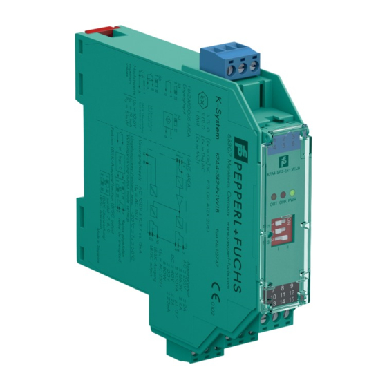
Switch Amplifier
KFA4-SR2-Ex1.W, KFA4-SR2-Ex1.W.LB, KFA4-SR2-Ex2.W
ATEX certificate: PTB 00 ATEX 2081
ATEX marking:
1
II (1)G [Ex ia Ga] IIC
1
II (1)D [Ex ia Da] IIIC
1
I (M1) [Ex ia Ma] I
IECEx certificate: IECEx PTB 11.0031
IECEx marking:
[Ex ia Ga] IIC
[Ex ia Da] IIIC
[Ex ia Ma] I
Switch Amplifier
KFA5-SR2-Ex1.W, KFA5-SR2-Ex1.W.LB, KFA5-SR2-Ex2.W,
KFA5-SR2-Ex2.W.IR, KFA6-SR2-Ex1.W, KFA6-SR2-Ex1.W.LB,
KFA6-SR2-Ex2.W, KFA6-SR2-Ex2.W.IR
ATEX certificate: PTB 00 ATEX 2081
ATEX marking:
1
II (1)G [Ex ia Ga] IIC
1
II (1)D [Ex ia Da] IIIC
1
I (M1) [Ex ia Ma] I
IECEx certificate: IECEx PTB 11.0031
IECEx marking:
[Ex ia Ga] IIC
[Ex ia Da] IIIC
[Ex ia Ma] I
North America Certificates: 1029981 (CSA), E106378 (UL)
Class I, Division 2, Groups A-D, T4
Class I, Zone 2, Group IIC T4
Associated apparatus with intrinsically safe circuits for:
Class I, Division 1, Groups A-D; Class II, Division 1, Groups E-G;
Class III
Class I, Zone 0, Group IIC
USA certificates: FM19US0207X
Class I, Division 2, Groups A-D, T4
Associated apparatus with intrinsically safe circuits for:
Class I, Division 1, Groups A-D; Class II, Division 1, Groups E-G;
Class III
Pepperl+Fuchs Group
Lilienthalstraße 200, 68307 Mannheim, Germany
Internet: www.pepperl-fuchs.com
2. Target Group, Personnel
Responsibility for planning, assembly, commissioning, operation,
maintenance, and dismounting lies with the plant operator.
The personnel must be appropriately trained and qualified in order to carry
out mounting, installation, commissioning, operation, maintenance, and
dismounting of the device. The trained and qualified personnel must have
read and understood the instruction manual.
Prior to using the product make yourself familiar with it. Read the
instruction manual carefully.
3. Reference to Further Documentation
Observe laws, standards, and directives applicable to the intended use
and the operating location.
For mining applications, observe laws, standards, and directives
applicable to the operating location.
The corresponding datasheets, manuals, declarations of conformity, EU-
type examination certificates, certificates, and control drawings if
applicable supplement this document. You can find this information under
www.pepperl-fuchs.com.
For specific device information such as the year of construction,
scan the QR code on the device. As an alternative, enter the serial number
in the serial number search at www.pepperl-fuchs.com.
If you use the device in safety-related applications, observe the
requirements for functional safety. You can find these requirements in the
functional safety documentation under www.pepperl-fuchs.com.
4. Intended Use
The device is only approved for appropriate and intended use.
Ignoring these instructions will void any warranty and absolve
the manufacturer from any liability.
The device is used in control and instrumentation technology
(C&I technology) for the galvanic isolation of signals such as 20 mA and
DOCT-6812 / 2023-03
10 V standard signals or alternatively for adapting or standardizing signals.
The device has intrinsically safe circuits that are used for operating
intrinsically safe field devices in hazardous areas.
The device transfers digital signals
(NAMUR sensors/mechanical contacts) from the explosion-
hazardous area to the non-explosion-hazardous area.
Use the device only within the specified ambient and operating conditions.
Only use the device stationary.
The device is an associated apparatus according to IEC/EN 60079-11.
The device may be installed in the non-hazardous area.
If you use the device in safety-related applications, observe the
information for safety function and safe state.
5. Improper Use
Protection of the personnel and the plant is not ensured if the device
is not used according to its intended use.
If circuits with type of protection Ex i are operated with non-intrinsically
safe circuits, they must no longer be used as circuits with type of
protection Ex i.
6. Mounting and Installation
Do not mount a damaged or polluted device.
The device is designed for mounting on a 35 mm DIN mounting rail
according to EN 60715.
Mount the device in a surrounding enclosure which provides protection
against electrical, mechanical and fire hazards.
Ensure that the surrounding enclosure can only be opened with a tool.
The device fulfills a degree of protection IP20 according to IEC/EN 60529.
The device must be installed and operated only in a controlled
environment that ensures a pollution degree 2 (or better) according to
IEC/EN 60664-1.
If used in areas with higher pollution degree, the device needs to be
protected accordingly.
Do not mount the device in the dust hazardous area.
The device must be installed and operated only in an environment of
overvoltage category II (or better) according to IEC/EN 60664-1.
Provide a disconnecting means for the supply of the device.
Observe the installation instructions according to IEC/EN 60079-14.
If you install the device in safety-related applications, observe the
requirements for functional safety.
Requirements for Cables and Connection Lines
Observe the permissible core cross section of the conductor.
When using stranded conductors, crimp wire end ferrules
on the conductor ends.
Use only copper conductors.
Use only one conductor per terminal.
When installing the conductors the insulation must reach
up to the terminal.
If the voltage is greater than 50 V AC or 120 V DC, switch off the voltage
before connecting or disconnecting the device.
Observe the tightening torque of the terminal screws.
Use conductors rated for a temperature of at least 80 °C.
Only use cables and connection lines with a temperature range
appropriate to the application.
Requirements for Usage as Associated Apparatus
If circuits with type of protection Ex i are operated with non-intrinsically
safe circuits, they must no longer be used as circuits with type of
protection Ex i.
Observe the respective peak values of the field device and the associated
apparatus with regard to explosion protection when connecting intrinsically
safe field devices with intrinsically safe circuits of associated apparatus
(verification of intrinsic safety). Also observe IEC/EN 60079-14 and
IEC/EN 60079-25.
Intrinsically safe circuits of associated apparatus can be led into
hazardous areas. Observe the compliance of the separation distances to
all non-intrinsically safe circuits according to IEC/EN 60079-14.
Observe the compliance of the separation distances between two
adjacent intrinsically safe circuits according to IEC/EN 60079-14.
Requirements for Division 2
The device must be installed and operated only in surrounding enclosures
that
comply with the requirements for surrounding enclosures according to
l
UL/CSA 60079-0,
are rated with the degree of protection IP54 according to
l
IEC/EN 60529.
Ensure that the surrounding enclosure can only be opened with a tool.
1 / 2
Advertisement

Related Manuals for Pepperl+Fuchs KFA4-SR2-Ex1.W


Summary of Contents for Pepperl+Fuchs KFA4-SR2-Ex1.W
- Page 1 Switch Amplifier Use the device only within the specified ambient and operating conditions. KFA4-SR2-Ex1.W, KFA4-SR2-Ex1.W.LB, KFA4-SR2-Ex2.W Only use the device stationary. ATEX certificate: PTB 00 ATEX 2081 The device is an associated apparatus according to IEC/EN 60079-11.
- Page 2 Connection or disconnection of energized non-intrinsically safe circuits is only permitted in the absence of a potentially explosive atmosphere. 7. Operation, Maintenance, Repair If you operate the device in safety-related applications, observe the requirements for functional safety. In case of operating in low demand mode, plan appropriate intervals for the proof test.