
Subscribe to Our Youtube Channel
Related Manuals for DFI TGU171


Summary of Contents for DFI TGU171
- Page 1 TGU171/TGU173 Mini-ITX Industrial Motherboard User’s Manual ©March 06, 2023 DFI Inc.
- Page 2 1. The changes or modifications not expressly approved by the party responsible for compliance could void the user’s authority to operate the equipment. 2. Shielded interface cables must be used in order to comply with the emission limits. User's Manual | TGU171/TGU173...
-
Page 3: Table Of Contents
Power & Performance ► GT- Power Management Control ......... 28 PCH-FW Configuration ....................29 Trusted Computing ......................29 PTN3460 Configuration ....................30 NCT6126D Super IO Configuration ................30 NCT6126D HW Monitor ....................31 NCT6126D HW Monitor ► Smart FAN Function ..........31 User's Manual | TGU171/TGU173... - Page 4 To avoid damage to the system, use the correct AC input voltage range. • To reduce the risk of electric shock, unplug the power cord before removing the system chassis cover for installation or servicing. After installation or servicing, cover the system chassis before plugging the power cord. User's Manual | TGU171/TGU173...
- Page 5 The board and accessories in the package may not come similar to the information listed above. This may differ in accordance with the sales region or models in which it was sold. For more information about the standard package in your region, please contact your dealer or sales representative. User's Manual | TGU171/TGU173...
-
Page 6: Chapter 1 - Introduction
1 x PCIe x4 (PCIe Gen 3 x4) 1 x M.2 2242/2280 M Key (PCIe Gen4 x4) (Support NVMe and Intel Optane memory) (Support DFI proprietary expansion module) ® 1 x M.2 2242/3042/3052 B Key (PCIe Gen3 x1/SATA/USB 3.1 Gen1) (Support 4G/5G and storage module) (Opt.: PCIe Gen3 x2) EXPANSION 1 x M.2 2230 E Key (USB2.0) (Support Intel... - Page 7 ENVIRONMENT MTBF TGU171-IE-1185GRE 414,291 hrs @ 25°C; 254,601 hrs @ 45°C; 166,963 hrs @ 60°; 124,264 hrs @ 70°C; TGU173-IE-1185GRE 397,863 hrs @ 25°C; 244,099 hrs @ 45°C; 160,483 hrs @ 60°; 119,765 hrs @ 70°C; Calculation model: Telcordia Issue 4 Environment: GB, GC – Ground Benign, Controlled Dimensions 170mm (6.7") x 170mm (6.7")
-
Page 8: Block Diagram
Chapter 1 INTRODUCTION X Dimension X Block Diagram User's Manual | TGU171/TGU173... -
Page 9: Chapter 2 - Hardware Installation
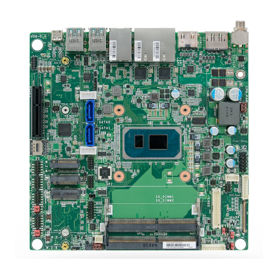
M.2-E Debug M.2-B DC-in COM4 RS232 Power HDMI COM4 DP++ COM3 RS232 Power LAN1 COM3 LAN2 COM2 2.5G LAN1 COM1 USB 1/2 (USB 3.1 Gen2) SIM slot USB 3/4 (USB 3.1 Gen2) PCIe x4 Front Audio User's Manual | TGU171/TGU173... -
Page 10: Installing The Heat Sink
If a wrist strap is unavailable, establish and maintain contact with the system chassis throughout any procedures requiring ESD protection. User's Manual | TGU171/TGU173... -
Page 11: Jumper Settings
„ 1-3 On: Standard RS232 (default) „ 2-4 On: Standard RS232(default) COM 3 RS232 Power (JP2) „ 1-2 On: Normal (default) „ 2-3 On: Clear CMOS Data „ 1-3 On: Standard RS232 (default) „ 2-4 On: Standard RS232(default) User's Manual | TGU171/TGU173... -
Page 12: Sata Selection (Jp8)
PCIe x1/SATA (controled USB3.0 SATA0 (via PCIe11) by M.2 Pin69) (from PCIe Switch) USB3.0 SATA0 (via PCIe11) SATA1 (via PCIe12) (from PCIe Switch) PCIe x2 (via PCIe11/12) „ 1-2 On: 5V (default) „ 2-3 On: 12V User's Manual | TGU171/TGU173... -
Page 13: Panel Power Jumper (Dpjp3)
Chapter 2 HARDWARE INSTALLATION Panel Backlight Selection (DPJP4) Panel Power Jumper (DPJP3) „ 1-2 On: 3.3V (default) „ 2-3 On: 5V „ 3-4 On: 5V „ 5-6 On: 3.3V (default) „ 1-2 On: 12V User's Manual | TGU171/TGU173... -
Page 14: Pin Assignment
Chapter 2 HARDWARE INSTALLATION X PIN Assignment CASEOPEN- SMBus SMBus CASEOPEN- Assignment Assignment Function Function 3V3SB CASEOPEN- SMB_CLK SMB_DATA SMB_ALERT User's Manual | TGU171/TGU173... -
Page 15: Digital I/O Power
Chapter 2 HARDWARE INSTALLATION Digital I/O Power Digital I/O Digital I/O Digital I/O Power Function Function Function Function +12V DIO_0 DIO_4 5VSB DIO_1 DIO_5 DIO_2 DIO_6 DIO_3 DIO_7 User's Manual | TGU171/TGU173... -
Page 16: Com 1 & Com 2
COM 1 & COM 2 COM 3 & COM 4 COM 3 COM 1 COM 4 COM 2 Function Function Function Function MDCD1(2)# MSIN1(2) X_MDCD3(4)# MSIN3(4)# MSOUT1(2) MDTR1(2)# MSO3(4)# MDTR3(4)# MDSR1(2)# MDSR3(4)# MRTS1(2)# MCTS1(2)# MRTS3(4)# MCTS3(4)# X_MRI3(4)# MRI1(2)# User's Manual | TGU171/TGU173... -
Page 17: Usb 5/6
Chapter 2 HARDWARE INSTALLATION USB 5/6 USB 7/8 USB 5/6 USB 7/8 Assignment Assignment Assignment Assignment USB2_7_C_N USB2_8_C_N USB2_5_C_N USB2_6_C_N USB2_7_C_P USB2_8_C_P USB2_5_C_P USB2_6_C_P N.C. N.C. User's Manual | TGU171/TGU173... -
Page 18: Sata0/1 Hdd Power
Chapter 2 HARDWARE INSTALLATION SATA0/1 HDD Power Front Audio SATA0 Power Front Audio SATA1 Power Assignment Assignment Assignment Assignment Mic2-L +12V_SATA Mic2-R N.C. 5V_SATA Line2-R Mic2-JD Line2-L Line2-JD User's Manual | TGU171/TGU173... -
Page 19: Lcd/Inverter Power
Chapter 2 HARDWARE INSTALLATION LCD/Inverter Power LCD/Inverter Power Assignment Panel Inverter Brightness Voltage Control Panel Power +3.3V Panel Backlight On/Off Control 12V / 5V (default) 12V / 5V (default) User's Manual | TGU171/TGU173... -
Page 20: Lvds
HARDWARE INSTALLATION LVDS Assignment Assignment LVDS_A3+ LVDS_B3+ LVDS_A3- LVDS_B3- LVDS_A2+ LVDS_B2+ LVDS LVDS_A2- LVDS_B2- LVDS_A1+ LVDS_B1+ LVDS_A1- LVDS_B1- LVDS_A0+ LVDS_B0+ LVDS_A0- LVDS_B0- LVDS_CLK1+ LVDS_CLK2+ LVDS_CLK1- LVDS_CLK2- LVDS_DDC_CLK LVDS_DDC_DATA +3.3V Panel Power Panel Power Panel Power Panel Power User's Manual | TGU171/TGU173... -
Page 21: Edp
Chapter 2 HARDWARE INSTALLATION Assignment Assignment eDPA_LANE3_C_N eDPA_LANE3_C_P eDPA_LANE2_C_N eDPA_LANE2_C_P eDPA_LANE1_C_N eDPA_LANE1_C_P eDPA_LANE0_C_N eDPA_LANE0_C_P eDPA_AUXP_C eDPA_AUXN_C EDP_VDD EDP_VDD EDP_VDD EDP_VDD eDPA_HPD EDP_BKLTEN EDP_BKLTCTL eDP_INV_PWR eDP_INV_PWR eDP_INV_PWR eDP_INV_PWR User's Manual | TGU171/TGU173... -
Page 22: Expansion Slots
M.2 Socket The M.2 socket is the Next Generation Form Factor (NGFF) which is designed to support multiple modules and make the M.2 more suitable in application for solid-state storage. SIM Card Slot For SIM card usage. User's Manual | TGU171/TGU173... -
Page 23: Expansion Slots
Screw tight the card onto the stand-off with a screw driver and a stand-off screw until the gap between the card and the stand-off closes up. The card should be lying parallel to the board when it’s correctly mounted. User's Manual | TGU171/TGU173... -
Page 24: Installing The So-Dimm Module
Inspect that the clip sits in the notch. If not, please pull Step 3 the clips outward, release and remove the card, and mount it again. 4 5 ° Step 1 User's Manual | TGU171/TGU173... -
Page 25: Chapter 3 - Bios Settings
To update the BIOS, you will need the new BIOS file and a flash utility. Please contact restart the system by pressing the <Ctrl> <Alt> and <Del> keys simultaneously. technical support or your sales representative for the files and specific instructions about how to update BIOS with the flash utility. User's Manual | TGU171/TGU173... -
Page 26: Main
The time format is <hour>, <minute>, <second>. The time is based on the 24-hour military-time clock. For example, 1 p.m. is 13:00:00. Hour displays hours from 00 to 23. Minute displays minutes from 00 to 59. Second displays seconds from 00 to 59. User's Manual | TGU171/TGU173... -
Page 27: Cpu Configuration
Enables this field for Windows XP and Linux which are optimized for Hyper-Threading technol- ogy. Select disabled for other OSes not optimized for Hyper-Threading technology. When dis- abled, only one thread per enabled core is enabled. Enable / Disable AES (Advanced Encryption Standard) User's Manual | TGU171/TGU173... -
Page 28: Power & Performance ► Cpu- Power Management Control
Disable Turbo GT frequency C states Enabled: Disables Turbo GT frequency. Disabled: GT frequency is not limited Enable or disable CPU Power Management. It allows CPU to enter "C states" when it’s idle and nothing is executing. User's Manual | TGU171/TGU173... -
Page 29: Pch-Fw Configuration
Configure Intel(R) Active Management Technology Parameters. ME Unconfig on RTC Clear When Disabled ME will not be unconfigured on RTC Clear. Firmware Update Configuration Note: Configure Management Engine Technology Parameters. The sub-menus are detailed in following sections. User's Manual | TGU171/TGU173... -
Page 30: Ptn3460 Configuration
Select PTN3460 LVDS BUS Mode : Single LVDS Bus /Dual LVDS Bus Note: Note: The configuration must match the specifications of your LCD Panel in order for the The sub-menus are detailed in following sections. LCD Panel to display properly. User's Manual | TGU171/TGU173... -
Page 31: Nct6126D Hw Monitor
▼ CPU/SYS Smart Fan Mode = [Manual Mode] Fix Fan Speed Count Set the fan speed, the value ranging from 1-100%, 100% being full speed. The fans will always operate at the specified speed regardless of gauged temperatures. User's Manual | TGU171/TGU173... -
Page 32: Serial Port Console Redirection
Select parity bits: None, Even, Odd, Mark or Space. Stop Bits Select stop bits: 1 bit or 2 bits. Flow Control Select flow control type: None or Hardware RTS/CTS. Flow Control is for RS485 mode and is only supported by Serial Port 1 (COM1). User's Manual | TGU171/TGU173... -
Page 33: Acpi Settings
The system automatically powers on after power failure. • S5 State The system enter soft-off state after power failure. Power-on signal input is required to power up the system. • Last State The system returns to the last state right before power failure. User's Manual | TGU171/TGU173... -
Page 34: Usb Configuration
USB Mass Storage Driver Support Enable or disable USB Mass Storage Driver Support. Port 60/64 Emulation Enables I/O port 60h/64h emulation support. This should be enabled for the complete USB keyboard legacy support for non-USB aware OSes. User's Manual | TGU171/TGU173... -
Page 35: Network Stack Configuration
Set the wait time in seconds to press ESC key to abort the PXE boot. Use either +/- or numeric keys to set the value. Media detect count Set the number of times the presence of media will be checked. Use either +/- or numeric keys to set the value. User's Manual | TGU171/TGU173... -
Page 36: Usb Power Control
Tls Auth Configuration Server CA Configuration Server CA Configuration 5_Dual: Support system wake up from S3/S4 by USB KB&MS Press <Enter> to configure Server CA. 5V: No support system wake up from S3/54 by USB KB&MS User's Manual | TGU171/TGU173... -
Page 37: Chipset
Please select a submenu and press Enter. The submenus are detailed in the following pages. Memory Configuration Memory Configuration Parameter. Graphics Configuration Settings about graphic. VMD setup menu VMD Configuration Settings PCI Express Configuration : VT-d VT-d capability. X2APIC Opt Out Enable/Disable X2APIC_OPT_OUT bit DMA Control Guarantee Enable/Disable DMA_Control_Guarantee bit User's Manual | TGU171/TGU173... -
Page 38: System Agent (Sa) Pch-Io Configuration
2048MB aperture. To use this feature, please disable CSM Support. DVMT Pre-Allocated Select DVMT 5.0 Pre-Allocated (Fixed) Graphics Memory Size used by the Internal Graphics Device. DVMT Total Gfx Mem Select DVMT 5.0 Total Graphic Memory Size used by the Internal Graphics Device. User's Manual | TGU171/TGU173... -
Page 39: Pch-Io Configuration► Pci Express Configuration
The mode selection determines how the SATA controller(s) operates. • AHCI This option allows the Serial ATA controller(s) to use AHCI (Advanced Host Controller Interface). Ports and Hot Plug Enable or disable the Serial ATA port and its hot plug function. User's Manual | TGU171/TGU173... -
Page 40: Pch-Io Configuration► Hd Audio Configuration
Chapter 3 BIOS SETTINGS Chipset PCH-IO Configuration ► HD Audio Configuration HD Audio Control the detection of the HD Audio device. • Disabled HDA will be unconditionally disabled. • Enabled HDA will be unconditionally enabled. User's Manual | TGU171/TGU173... -
Page 41: Security
Clear the database from the NVRAM, including all the keys and signatures installed in the Key Management menu. Press Enter and a prompt will show up for you to confirm. Key Management Enables expert users to modify Secure Boot Policy variables without full authentication. User's Manual | TGU171/TGU173... -
Page 42: Boot
• Restore Setting from file This field will appear only when a USB flash device is detected. Refer to the Advanced > CSM Configuration submenu for more information. Select this field to restore set-ting from the USB flash device. User's Manual | TGU171/TGU173...
Need help?
Do you have a question about the TGU171 and is the answer not in the manual?
Questions and answers