Table of Contents
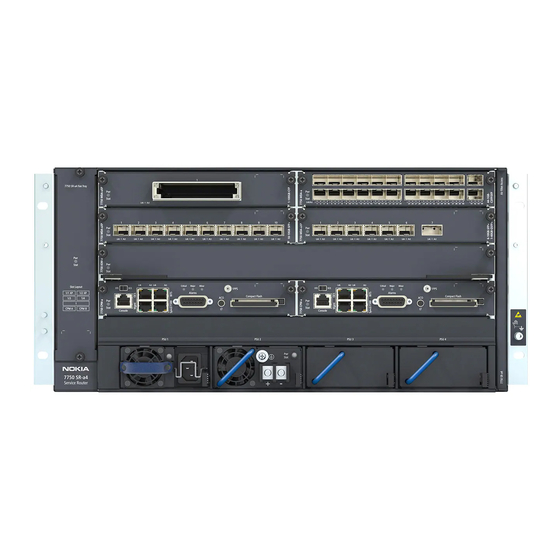
Advertisement
Advertisement
Table of Contents

Related Manuals for Nokia 7750 SR


Summary of Contents for Nokia 7750 SR
- Page 1 7750 SR ESA 100G Chassis Installation Guide Release 20.5 7750 SR Extended Services Appliance 7750 SR ESA 100G Chassis Installation Guide Release 20.5 3HE 16094 AAAA TQZZA Issue: 01 July 2020 Nokia — Proprietary and confidential. Use pursuant to applicable agreements.
- Page 2 © 2020 Nokia. All rights reserved. Contains proprietary/trade secret information which is the property of Nokia and must not be made available to, or copied or used by anyone outside Nokia without its written authorization. Not to be used or disclosed except in accordance with applicable agreements.
-
Page 3: Table Of Contents
1.1.4 Technical Support..................11 System Overview ................13 Hardware Specifications................14 Safety and Compliance Agency Certifications...........15 Chassis Description...................16 Setting up an ESA in a 7750 SR System ..........18 Site Preparation ................19 Safety Warnings ..................19 Site Selection.....................20 Installation Locations .................21 Ethernet Cabling ..................23 Installation..................25 Rack-mounting the Chassis...............26... - Page 4 7750 SR ESA 100G Chassis Installation Guide Release 20.5 3HE 16094 AAAA TQZZA Issue: 01...
- Page 5 Information Symbol/Labels ..............10 System Overview ................13 Table 2 7750 SR ESA 100G Hardware Specifications ..........14 Table 3 7750 SR ESA 100G Front Panel Features ..........16 Table 4 7750 SR ESA 100G Rear Panel Features ..........17 Site Preparation ................19 Table 5 Environmental Specifications ..............22...
- Page 6 7750 SR ESA 100G Chassis Installation Guide Release 20.5 3HE 16094 AAAA TQZZA Issue: 01...
- Page 7 Release 20.5 List of Figures System Overview ................13 Figure 1 7750 SR ESA 100G Front Panel Features..........16 Figure 2 7750 SR ESA 100G Rear Panel Features ..........17 Installation..................25 Figure 3 Slide Rail Assembly...................27 Figure 4 Installing Inner Rails ..................28 Figure 5 Installing Outer Rail ...................29...
- Page 8 7750 SR ESA 100G Chassis Installation Guide Release 20.5 3HE 16094 AAAA TQZZA Issue: 01...
-
Page 9: Preface
This guide provides a system overview of the 7750 SR Extended Services Appliance (ESA) 100G chassis, site preparation recommendations, step-by-step rack-mounting procedures, and instructions about how to set up an ESA in a 7750 SR system. Each 7750 SR ESA 100G chassis is shipped with rack-mounting brackets. -
Page 10: Symbols And Labels
Preface 7750 SR ESA 100G Chassis Installation Guide Release 20.5 1.1.3 Symbols and Labels Table 1 lists the symbols and labels contained in this guide. Information Symbol/Labels Table 1 Symbol Meaning Description Danger This symbol warns that incorrect handling and installation could result in bodily injury or death. -
Page 11: Technical Support
Release 20.5 1.1.4 Technical Support If you purchased a service agreement for the 7750 SR ESA 100G and related products from a distributor or authorized reseller, contact the technical support staff for that distributor or reseller for assistance. If you purchased a Nokia service... -
Page 12: System Overview
SR system and on the ESA NIC. For more information about which specific 7750 SR interface cards support connections to the 7750 SR ESA 100G, refer to SR OS Software Release Notes. The chassis arrives fully assembled and must be installed in a rack; see... -
Page 13: Hardware Specifications
System Overview 7750 SR ESA 100G Chassis Installation Guide Release 20.5 2.1 Hardware Specifications 7750 SR ESA 100G Hardware Specifications Table 2 Category Requirements Form factor 1 RU Size W x H x D: 17.3 x 1.7 x 30.7 in. (440 x 43.2 x 780 mm) Weight 45.64 lb (20.7 kg) -
Page 14: Safety And Compliance Agency Certifications
7750 SR ESA 100G Chassis Installation Guide System Overview Release 20.5 2.2 Safety and Compliance Agency Certifications The 7750 SR ESA 100G hardware is compliant with the following standards: Safety • IEC 62368-1 with national deviations Environmental Compliance • EMC compliance according to EN 300 386, FCC 47 CFR Part 15 and GR -1089-CORE •... -
Page 15: Chassis Description
System Overview 7750 SR ESA 100G Chassis Installation Guide Release 20.5 2.3 Chassis Description Figure 1 shows the front panel features of the 7750 SR ESA 100G chassis. 7750 SR ESA 100G Front Panel Features Figure 1 hw0378 Table 3 describes the front panel features, including LED behavior. -
Page 16: Table 3 7750 Sr Esa 100G Front Panel Features
USB ports 1 and 2 (not used) HDD bays 4 x 3.5 in. SATA/SAS drives (not used) Figure 2 shows the rear-panel features of the 7750 SR ESA 100G chassis. 7750 SR ESA 100G Rear Panel Features Figure 2 hw0825 Table 4 describes the rear panel features, including LED behavior. -
Page 17: Setting Up An Esa In A 7750 Sr System
Backup BMC SEL (not used) 2.4 Setting up an ESA in a 7750 SR System To set up an ESA in a 7750 SR system, the following actions must be completed in any order: • install the ESA hardware in a rack, then apply power to the ESA hardware •... -
Page 18: Site Preparation
7750 SR ESA 100G Chassis Installation Guide Site Preparation Release 20.5 3 Site Preparation This chapter describes site preparation for the 7750 SR ESA 100G and includes the following topics: • Safety Warnings, section 3.1 • Site Selection, section 3.2 •... -
Page 19: Site Selection
• The equipment under test (EUT) is specified for DC-I power configurations. The battery returns must remain isolated until they reach the main power bus. • The 7750 SR ESA 100G with DC power supply should be installed only in restricted access areas (such as dedicated equipment rooms and electrical closets) in accordance with Articles 110-26 and 110-27 of the most recent National Electrical Code ANSI/NFPA 70. -
Page 20: Installation Locations
When a 7750 SR ESA 100G is installed in an outside plant, such as a cell site, hut, cabinet, or outside plant enclosure, it must be installed in an environment where, except during installation and servicing, the compartment is sealed or properly filtered. -
Page 21: Table 5 Environmental Specifications
• The rail mounting holes in the equipment rack must align with the mounting holes on the chassis mounting brackets. The 7750 SR ESA 100G mounting brackets are factory-installed for mounting in a 19-inch rack. 3HE 16094 AAAA TQZZA... -
Page 22: Ethernet Cabling
• Avoid installing copper cables close to strong electromagnetic fields generated by electric generators, elevator engines, or other similar heavy electric machines. • Make sure you only use SFPs that are supported by Nokia. Issue: 01 3HE 16094 AAAA TQZZA... -
Page 23: Installation
7750 SR ESA 100G Chassis Installation Guide Installation Release 20.5 4 Installation This chapter describes installation of the 7750 SR ESA 100G and includes the following topics: • Rack-mounting the Chassis, section 4.1 • Connecting to AC Power, section 4.2 •... -
Page 24: Rack-Mounting The Chassis
• a screwdriver (Phillips or flathead, depending on the type of screws used) • an available grounding point near the installation location To rack-mount the 7750 SR ESA 100G with fixed rack-mount brackets: Step 1. Attach the rack-mount brackets to the chassis with screws (supplied). -
Page 25: Rack-Mounting The Chassis With Slide Rails
• a screwdriver (Phillips or flathead, depending on the type of screws used) • an available grounding point near the installation location To rack-mount the 7750 SR ESA 100G chassis using slide rails: Step 1. Remove the rail from the package and extend the rail fully. -
Page 26: Figure 4 Installing Inner Rails
Installation 7750 SR ESA 100G Chassis Installation Guide Release 20.5 Step 3. Align the holes on the inner rails with the chassis as shown in Figure Installing Inner Rails Figure 4 hw0872 Step 4. Slide the inner rails forward to lock them in place. -
Page 27: Figure 5 Installing Outer Rail
7750 SR ESA 100G Chassis Installation Guide Installation Release 20.5 Step 6. Press the rear part of the outer one to the rear rack post. The rail locks into the rear post. Step 7. Extend the front of the rail. -
Page 28: Figure 6 Installing The Chassis
Installation 7750 SR ESA 100G Chassis Installation Guide Release 20.5 Step 10. Pull the middle rail forward to fully extend it in the locked position. Step 11. Align the chassis with the middle rails as shown in Figure Installing the Chassis... -
Page 29: Figure 7 Sliding The Chassis Into The Rack
7750 SR ESA 100G Chassis Installation Guide Installation Release 20.5 Step 12. Slide the chassis into the rack until it stops. Step 13. Push in the blue release tab on the inner rails and continue sliding the chassis into the rack as shown in... -
Page 30: Figure 8 Securing The Chassis
Installation 7750 SR ESA 100G Chassis Installation Guide Release 20.5 Step 14. Secure the chassis in the rack with the thumb screws (supplied) as shown Figure Securing the Chassis Figure 8 hw0875 Step 15. Ground the chassis to earth. 3HE 16094 AAAA TQZZA... -
Page 31: Connecting To Ac Power
Power Ports, an external Surge Protective Device is intended to be used at the AC input of the unit. The following AC power cables are used with the 7750 SR ESA 100G: • NEMA 5-15P to EC 60320 C13 10A/110V, 1.8 meter (USA, Canada, South America) •... -
Page 32: Connecting To Dc Power
• The 7750 SR ESA 100G is capable of operating -39 VDC to -72 VDC at 37 A maximum current level. -
Page 33: Table 6 Dc Power Connection Diagram Description
7750 SR ESA 100G Chassis Installation Guide Installation Release 20.5 Step 5. Using a small flat-tip screwdriver, connect the ground wire to the DC power cable connector by inserting the ground wire directly into the ground (center) terminal on the connector as shown in... - Page 34 7750 SR ESA 100G Chassis Installation Guide Transceivers Release 20.5 5 Transceivers This chapter describes how to work with transceivers on ports that support these devices and includes the following topics: • Warnings and Notes, section 5.1 • Installation Preparation, section 5.2 •...
-
Page 35: Transceivers
Release 20.5 Figure 10 shows the ESD awareness label used on Nokia products to alert personnel to the presence of ESD-sensitive devices in the product. The necessary ESD precautions must be taken whenever this symbol is present on the product. -
Page 36: Locking And Release Mechanisms
Transceivers Release 20.5 5.2.1 Locking and Release Mechanisms Nokia transceivers can use different lock and release methods. Possible lock and release mechanisms include: • locking handle—a locking handle (lever) in the front of the transceiver that you gently raise or lower to insert or remove from the port •... -
Page 37: Removing And Replacing Transceivers
Transceivers 7750 SR ESA 100G Chassis Installation Guide Release 20.5 5.2.3 Removing and Replacing Transceivers When you are replacing a transceiver, have the following parts ready: • a replacement transceiver • protective plugs for the transceiver and a dust cover for the fiber cable connector •... - Page 38 Customer Document and Product Support Customer Documentation Customer Documentation Welcome Page Technical Support Product Support Portal Documentation Feedback Customer Documentation Feedback...
- Page 39 © 2020 Nokia. 3HE 16094 AAAA TQZZA...
Need help?
Do you have a question about the 7750 SR and is the answer not in the manual?
Questions and answers