
Related Manuals for eta ePE-K 100 kW


Summary of Contents for eta ePE-K 100 kW
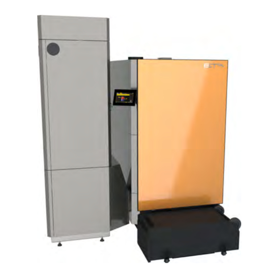
- Page 1 2022-04-04 0000000441 V.005 3.55.0 5208, 01 939067-002 Pellet boiler ePE-K 100-130 kW Service manual...
- Page 2 ETA Heiztechnik Gewerbepark 1 A-4716 Hofkirchen an der Trattnach Tel: +43 (0) 7734 / 22 88 -0 Fax: +43 (0) 7734 / 22 88 -22 info@eta.co.at www.eta.co.at...
-
Page 3: Table Of Contents
Contents General information ..............4 Cleaning and maintenance . -
Page 4: General Information
Commissioned by (company): _________________________________________ _________________________________________ _________________________________________ Copyright All contents of this document are property of ETA Heiztechnik GmbH and are protected by copyright. Any reproduction, transfer to third parties or use for other purposes is prohibited without written permission from the owner. -
Page 5: Cleaning And Maintenance
Cleaning and maintenance Maintenance notes Cleaning and maintenance Maintenance notes To access maintenance, switch to settings in the boiler function block ( [Settings] button) and then select the function [Maintenance]. Performing regular cleaning and maintenance To ensure satisfactory functionality, cleaning and maintenance must be performed at regular intervals. - Page 6 Lambda probe). Handle the components carefully, since they break very easily. Measure or check dimensions or clearances on the components. Fig. 2-4: Maintenance switch Mark the components so that the correct po- sition can be determined, for example, when mounting. www.eta.co.at...
- Page 7 Cleaning and maintenance Maintenance notes Wear a protective mask to avoid damage to the airways. Seal the components. The sealant to be used is listed in the respective step. Insulate the components. The insulation ma- terial to be used is indicated in the respective step.
-
Page 8: Maintenance Openings In The Boiler
Pellets vacuum turbine Fill level sensor for pellet hopper Combustion chamber door Firebed switch (safety switch) Vacuum sensor Firebed level sensor Actuator for primary air Grate drive Ash screw 10 Grate position switch 11 Connection for negative-pressure measurement www.eta.co.at... - Page 9 Cleaning and maintenance Maintenance openings in the boiler Actuator for secondary air Drive chain of the dosing screw Position sensor for stoker screw Drive chain of the stoker screw Ignition Retaining tube of the lambda probe Heat exchanger cleaner maintenance cover Safety switch for the maintenance cover De-ashing drive 10 Flue gas temperature sensor in heat exchanger...
- Page 10 Maintenance openings in the boiler Cleaning and maintenance Actuator of flue gas recirculation Precipitator maintenance cover Heat exchanger cover Release button for safety temperature limiter (STB) Mains switch (symbol Maintenance switch (symbol Door contact switch www.eta.co.at...
-
Page 11: Maintenance Table
Cleaning and maintenance Maintenance table Maintenance table Clean the boiler at least once a year or when requested by the control system. Maintenance is necessary at least every 3 years or when requested by the control system. We recommend you perform maintenance annually. - Page 12 Check the stoker drive chains • Check the clearance/gap of the position sensor for the Specialist stoker screw • Clean the fill level sensor • Clean strainer Calibrating the lambda probe Specialist Reset maintenance counter Specialist Perform heating test Specialist www.eta.co.at...
- Page 13 Cleaning and maintenance Maintenance table...
-
Page 14: Regular Maintenance
To empty the ash box, fold the locking lever on the boiler forward. Remove the ash box from the boiler. Fig. 3-1: Locking lever Close the flap on the ash box. Fig. 3-2: Flap www.eta.co.at... - Page 15 Regular maintenance Empty the ash box Open the lock for the lid and empty the ash box. Check that the ash box seal on the boiler is intact and replace it if necessary. Fig. 3-5: Seal Fig. 3-3: Lid Attaching the ash box to the boiler Check the ashes for pieces of embers.
-
Page 16: Check Pressure Of The Heating System
(e.g. treated water). Establish operational readiness Switching on the boiler Switch the boiler back on using the on / off switch . www.eta.co.at... - Page 17 Regular maintenance Establish operational readiness...
-
Page 18: Cleaning (Customer)
Risk of burning on parts located behind the boiler housing, even after shutting the boiler down. Fig. 4-1: Locking lever Allow the boiler to cool down sufficiently before starting any activities. Close the flap on the ash box. Fig. 4-2: Flap www.eta.co.at... - Page 19 Cleaning (customer) Empty the ash box Open the lock for the lid and empty the ash box. Check that the ash box seal on the boiler is intact and replace it if necessary. Fig. 4-5: Seal Fig. 4-3: Lid Attaching the ash box to the boiler Check the ashes for pieces of embers.
-
Page 20: Check Pressure Of The Heating System
Therefore, only carry out the check on weekdays, never on weekends in the cold winter, because there is probably no heating technician available if the seal is defective. www.eta.co.at... -
Page 21: Chimney
Cleaning (customer) Chimney Chimney Checking the thermal relief valve Visually check the thermal relief valve. The outlet must not drip. Clean the flue duct Sweep the flue duct from the flue outlet to the chimney and remove the fly ash from the chimney with an ash vacuum cleaner. -
Page 22: Removing Panels
Remove the cover from the front of the boiler. Fig. 4-13: Combustion chamber Cleaning the primary and secondary combustion chamber In the primary combustion chamber remove the two- part combustion chamber cover. Fig. 4-12: Cover Fig. 4-14: Combustion chamber cover www.eta.co.at... - Page 23 Cleaning (customer) Cleaning the combustion chamber Using the poker, stoke all the ash out of the primary Cleaning the tilting grate combustion chamber into the secondary combustion Clean the tilting grate as well as the openings in the chamber. tilting grate with the poker. Allow the ash to fall down. Fig.
- Page 24 Check the movement of the firebed lever in the combustion chamber by repeated lifting. Fig. 4-23: Combustion chamber cover Fig. 4-20: Firebed lever The firebed switch on the front of the boiler must be actuated when lifting. Fig. 4-21: Firebed switch www.eta.co.at...
-
Page 25: Clean Flue Gas Ducts
Cleaning (customer) Clean flue gas ducts Clean flue gas ducts Clean the PTFE sealing washer on the air valve or replace it if damaged. Checking the air valve for flue gas recirculation Actuate the air valve actuator manually and check that it moves smoothly. - Page 26 Removing the maintenance cover Remove the insulation above the maintenance cover. Fig. 4-33: Flue gas duct Removing the cover on the ash duct Remove the cover on the front of the ash duct. Fig. 4-31: Insulation Fig. 4-34: Cover www.eta.co.at...
- Page 27 Cleaning (customer) Clean flue gas ducts Cleaning the flue gas recirculation ducts Mounting the cover on the ash duct Remove the maintenance cover and the enclosed seal Re-install the cover on the front of the ash duct. for the primary air valve. Fig.
-
Page 28: Clean Precipitator (Optional)
Removing the maintenance cover Remove the insulation above the maintenance cover. Fig. 4-42: Insulation Fig. 4-40: Maintenance cover Remove the maintenance cover. Place the insulation back onto the maintenance cover. Fig. 4-41: Insulation Fig. 4-43: Maintenance cover www.eta.co.at... - Page 29 Use an ash vacuum to vacuum out the opening for the small holes can be "felt", there is damage. In this case, flushing air from the electrode at the isolator. contact ETA Customer Support. Check the alignment of the electrodes The electrode must be in the centre of the precipitator, so that the flue gas can be optimally cleaned.
-
Page 30: Attaching Panels
Switch the boiler on via the mains switch and start ash removal Switch the boiler back on at the mains switch. Press the [De-ashing] button for the boiler to start the de- ashing process. Switch the boiler back on using the on / off switch www.eta.co.at... - Page 31 Cleaning (customer) Establish operational readiness...
-
Page 32: Maintenance (Expert)
WARNING! Burns caused by hot parts Risk of burning on parts located behind the boiler housing, even after shutting the boiler down. Fig. 5-2: Flap Allow the boiler to cool down sufficiently before starting any activities. www.eta.co.at... - Page 33 Maintenance (expert) Empty the ash box Open the lock for the lid and empty the ash box. Check that the ash box seal on the boiler is intact and replace it if necessary. Fig. 5-5: Seal Fig. 5-3: Lid Checking the ash box position switch Check the ashes for pieces of embers.
-
Page 34: Check Pressure Of The Heating System
The safety valve triggers at approx. 2.8 bar. If the water pressure drops several times a year, contact a heating professional. When refilling water in the heating system, the same water as used during initial filling should be used whenever possible (e.g. treated water). www.eta.co.at... -
Page 35: Check Safety Devices
Maintenance (expert) Check safety devices Check safety devices Checking the thermal relief valve Visually check the thermal relief valve. The outlet must not drip. Check safety valves Check all safety valves of the heating system by means of a visual inspection. The outlets of the safety valves must not drip. -
Page 36: Chimney
To check, rinse the outlet with some water. Fig. 5-13: Side covers Remove the cover on the front Remove the cover from the front of the boiler. Fig. 5-11: Condensate drain Fig. 5-14: Cover www.eta.co.at... -
Page 37: Cleaning The Combustion Chamber
Maintenance (expert) Cleaning the combustion chamber Cleaning the combustion Using the poker, stoke all the ash out of the primary combustion chamber into the secondary combustion chamber chamber. Cleaning the inside of the combustion chamber Open the combustion chamber door and use the poker to scrape off the ash from the inner surfaces of the combustion chamber. - Page 38 Clean the opening for the secondary air (above the tilting grate) with an ash vacuum, for example. Fig. 5-22: Firebed lever The firebed switch on the front of the boiler must be Fig. 5-20: Secondary air openings actuated when lifting. Fig. 5-23: Firebed switch www.eta.co.at...
-
Page 39: Clean Flue Gas Ducts
Maintenance (expert) Clean flue gas ducts Clean flue gas ducts Check fire clay Check the fire clay in the primary and secondary combustion chamber for damage and cracks. Checking the air valve for flue gas recirculation Actuate the air valve actuator manually and check that Replacing the combustion chamber cover it moves smoothly. - Page 40 Never lubricate the sealing area in the flue duct or the washer on the air valve with oil, grease or other lubricants. The reason for this is because dust particles in the flue gas adhere to the lubricant and cause encrustation and sluggishness. Fig. 5-33: Insulation www.eta.co.at...
- Page 41 Maintenance (expert) Clean flue gas ducts Remove the maintenance cover. Checking the seal on the maintenance cover Check if the seal on the maintenance cover is intact and replace if necessary. Fig. 5-34: Maintenance cover Cleaning the inner walls of the flue gas duct Fig.
-
Page 42: Clean Precipitator (Optional)
Clean precipitator (optional) Maintenance (expert) Clean precipitator (optional) Place the insulation back onto the maintenance cover. Removing the maintenance cover Remove the insulation above the maintenance cover. Fig. 5-38: Insulation Fig. 5-39: Insulation Remove the maintenance cover. Fig. 5-40: Maintenance cover www.eta.co.at... - Page 43 Use an ash vacuum to vacuum out the opening for the small holes can be "felt", there is damage. In this case, flushing air from the electrode at the isolator. contact ETA Customer Support. Check the alignment of the electrodes The electrode must be in the centre of the precipitator, so that the flue gas can be optimally cleaned.
-
Page 44: Cleaning The Heat Exchanger
Fig. 5-48: Heat exchanger cover Fig. 5-46: Insulation Cleaning the heat exchanger Strip off the ashes on the inner walls with the poker and remove the fly ash with an ash vacuum, for example. Fig. 5-49: Heat exchanger www.eta.co.at... - Page 45 Maintenance (expert) Cleaning the heat exchanger Checking the heat exchanger tubes Closing the heat exchanger cover Check the heat exchanger tubes and the turbulators Replace the heat exchanger cover and tighten the nuts for "tar deposits" (shiny soot). alternately and evenly. Fig.
-
Page 46: Clean Draught Fan
Remove the ash from the fan housing. Fig. 5-55: Fan housing Carefully clean the impeller with a soft brush (not a wire brush) or compressed air to prevent imbalance. Replace the seal. Fig. 5-56: Clean the impeller, replace the seal www.eta.co.at... -
Page 47: Check Air Valve
Maintenance (expert) Check air valve 5.12 Check air valve Inspect the integrity of the seal and replace it if necessary. A glued ceramic fibre seal can also be used as a seal. Removing the cover on the ash duct Remove the cover on the front of the ash duct. Fig. -
Page 48: Check Underpressure Sensor
(e.g. PTFE spray) if they are difficult to move. silicone hose behind it. Mounting the cover on the ash duct Re-install the cover on the front of the ash duct. Fig. 5-68: Cover Fig. 5-65: Cover www.eta.co.at... -
Page 49: Check De-Ashing
Maintenance (expert) Check de-ashing 5.14 Check de-ashing Calibrate the vacuum sensor With the boiler switched off and silicone hose removed, the control system must display a measured Checking the de-ashing value of 0 Pa. This measured value can be seen with Dismantle the maintenance cover of the heat the [Service] authorisation in the text menu under: exchanger cleaner. -
Page 50: Clean Temperature Sensor
Do not operate with damaged seals Never operate the boiler with damaged seals. Otherwise, unwanted air is sucked in, disturbing the combustion process and causing increased wear. Always replace damaged seals immediately. Fig. 5-73: Flue gas temperature sensor in heat exchanger www.eta.co.at... -
Page 51: Attaching Panels
Maintenance (expert) Attaching panels 5.17 Attaching panels Mount the heat exchanger cleaner maintenance cover. Replace the maintenance cover of the heat exchanger Installing the side covers cleaner. Tighten the screws alternately and evenly. Re-install the side covers on the boiler. Fig. -
Page 52: Check Boiler Doors
Fig. 5-82: Reduceing the gap Fig. 5-81: Seal Also check if the sealing cord is already "hard". To check, press on the sealing cord with your finger nail. If it can no longer be pressed, it is "hard" already and must be replaced. www.eta.co.at... -
Page 53: Check Pellet Hopper
Maintenance (expert) Check pellet hopper 5.19 Check pellet hopper Retighten the flange nuts. Suspend the door and check whether it now closes fully. If not, repeat the process. Removing the collector from the pellet hopper Remove the cover from the pellet hopper. Fig. - Page 54 Re-install the cover back onto the pellet hopper. Cleaning the fill level sensor Mark the correct installation position of the mounting panel for the fill level sensor, e.g. with a pen. Fig. 5-87: Cover Fig. 5-89: Marking the installation position www.eta.co.at...
- Page 55 Maintenance (expert) Check pellet hopper Remove the filling level sensor mounting panel. Re-installing the fill level sensor Re-install the mounting panel with the fill level sensor back on the pellet hopper. Observe the correct installation position. Fig. 5-90: Mounting panel for fill level sensor Check the seal on the bottom of the mounting panel Fig.
-
Page 56: Calibrate Lambda Probe
If possible, perform a flue gas measurement during test heating. Full load hours since maintenance Reset counter? After the heating test, switch the boiler back to normal mode. To do this, press the [Deactivate measurement] button in the settings window. www.eta.co.at... - Page 58 www.eta.co.at...
- Page 60 DOWNLOAD www.eta.co.at...
Need help?
Do you have a question about the ePE-K 100 kW and is the answer not in the manual?
Questions and answers