Advertisement
Quick Links
Advertisement

Related Manuals for Siemens SIEMOSYN 1FU8 Series


Summary of Contents for Siemens SIEMOSYN 1FU8 Series
- Page 1 Planning Guide 09/2003 Edition siemosyn SINAMICS SIMOVERT MASTERDRIVES MICROMASTER 1FU8 Motors...
-
Page 3: Table Of Contents
Motor Description Electrical Design Mechanical Design SINAMICS SIMOVERT MASTERDRIVES MICROMASTER Technical Data and Cantilever Forces SIEMOSYN Motors Engineering Information 1FU8 Planning Guide Dimensions and Weights Distributed Drive Technology References Index 09.2003 Edition... - Page 4 SIMATICr, SIMATIC HMIr, SIMATIC NETr, SIROTECr, SINUMERIKr, SINAMICSr, SIEMOSYNr, SIMODRIVEr, MASTERDRIVESr, MICROMASTERr and MOTION-CONNECTr are registered trademarks of Siemens AG. Other names in this publication might be trademarks whose use by a third party for his own purposes may violate the rights of the registered holder.
- Page 5 The sales contract contains the entire obligation of Siemens. The warranty contained in the contract between the parties is the sole warranty of Siemens. Any statements contained herein neither create new warranties nor modify the existing warranty.
- Page 6 Note In the sense of this document there is a possible advantage/benefit if the note text is observed. Siemens AG, 2003. All rights reserved SIEMOSYN Motors, 1FU8 (PFU) – 09.03 Edition...
- Page 7 – they may not be damaged – they may not be strained, and – they may not be able to be touched by rotating components. Siemens AG, 2003. All rights reserved SIEMOSYN Motors, 1FU8 (PFU) – 09.03 Edition...
- Page 8 S SIMOVERT MASTERDRIVES/MICROMASTER/SINAMICS drive units with AC motors fulfill, in the configurations which are specified in the associated EC Declaration of Conformance, the EMC Directive 89/336/EEC. Siemens AG, 2003. All rights reserved viii SIEMOSYN Motors, 1FU8 (PFU) – 09.03 Edition...
- Page 9 – the measuring device is grounded (e.g. via the protective conductor) or – for floating measuring equipment, the probe is briefly discharged before making measurements (e.g. a bare control housing is touched). Siemens AG, 2003. All rights reserved SIEMOSYN Motors, 1FU8 (PFU) – 09.03 Edition...
- Page 10 Preface 09.03 Notes Siemens AG, 2003. All rights reserved SIEMOSYN Motors, 1FU8 (PFU) – 09.03 Edition...
- Page 11 ........1FU8/4-62 Siemens AG, 2003. All rights reserved 1FU8-11...
- Page 12 ............Index–83 Siemens AG, 2003. All rights reserved 1FU8-12...
-
Page 13: Motor Description
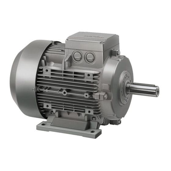
The motors are available as standard up to a speed of 15,000 [RPM]. They provide a constant drive-out torque over a wide frequency/speed range. Fig. 1-1 SIEMOSYN 1FU8 motor Siemens AG, 2003. All rights reserved 1FU8/1-13 SIEMOSYN Motors, 1FU8 (PFU) – 09.03 Edition... - Page 14 S Man-made fiber industry (spinning pumps, godets, driving rolls) S Texturing systems (stretching godets) S Rolling mills (roller table motors) S Transport systems (conveyor belts) S Glass industry (conveyor belts) Siemens AG, 2003. All rights reserved 1FU8/1-14 SIEMOSYN Motors, 1FU8 (PFU) – 09.03 Edition...
- Page 15 Drive-end bearings for increased cantilever forces Regreasing device Forced ventilation Terminal box mounted to the left or right Modular built-on brake Gearbox mounting Mounted modular frequency converter with/or without gear Siemens AG, 2003. All rights reserved 1FU8/1-15 SIEMOSYN Motors, 1FU8 (PFU) – 09.03 Edition...
- Page 16 6 = 200 V / 50 Hz 8 = 400 V / 50 Hz Type of construction Special versions and options Refer to Catalog DA48 and M11 Siemens AG, 2003. All rights reserved 1FU8/1-16 SIEMOSYN Motors, 1FU8 (PFU) – 09.03 Edition...
- Page 17 Brake supply voltage, 2-ph. 400 V AC, 50 Hz Mounted brake, 1-ph. 230 V AC, 50/60 Hz Mechanical manual brake release with lever Mounted separately-driven fan Siemens AG, 2003. All rights reserved 1FU8/1-17 SIEMOSYN Motors, 1FU8 (PFU) – 09.03 Edition...
- Page 18 Without Safety and Start-up Guide. The customer must provide a waiver With one Safety and Start-up Guide for each wire lattice pallet Factory test certificate 2.3 according to EN 10 204 Siemens AG, 2003. All rights reserved 1FU8/1-18 SIEMOSYN Motors, 1FU8 (PFU) – 09.03 Edition...
- Page 19 S Type of construction B5 S Special versions –Z – PTC thermistor for alarm and shutdown – Radial shaft sealing ring, When ordering, specify: 1FU8 083–4TA31–Z A12 + K17 Siemens AG, 2003. All rights reserved 1FU8/1-19 SIEMOSYN Motors, 1FU8 (PFU) – 09.03 Edition...
- Page 20 7) Type of construction 8) Frame size 9) Degree of protection 10) Temperature class 11) Motor data 12) Voltage 13) Frequency 14) Bearing size DE/NDE Siemens AG, 2003. All rights reserved 1FU8/1-20 SIEMOSYN Motors, 1FU8 (PFU) – 09.03 Edition...
- Page 21 7) Type of construction 8) Frame size 9) Degree of protection 10) Temperature class 11) Motor data 12) Voltage 13) Frequency 14) Bearing size DE/NDE Siemens AG, 2003. All rights reserved 1FU8/1-21 SIEMOSYN Motors, 1FU8 (PFU) – 09.03 Edition...
- Page 22 Motor Description 09.03 1.4 Rating plate data Notes Siemens AG, 2003. All rights reserved 1FU8/1-22 SIEMOSYN Motors, 1FU8 (PFU) – 09.03 Edition...
-
Page 23: Electrical Design
In order to optimally dimension SIEMOSYN 1FU8 motors, the winding can be adapted to the customer’s application (11th position of the Order No.: “9”, the volt- age and frequency is specified in plain text). Siemens AG, 2003. All rights reserved 1FU8/2-23 SIEMOSYN Motors, 1FU8 (PFU) – 09.03 Edition... - Page 24 All of the motors have an insulation according to temperature Class F and the mo- tors are utilized, at the rated power (when fed directly from the line supply or fre- quency converter) to temperature Class F. Siemens AG, 2003. All rights reserved 1FU8/2-24 SIEMOSYN Motors, 1FU8 (PFU) – 09.03 Edition...
- Page 25 The motor is accelerated with a constant torque (max. torque M ) as a result of the specified characteristic V/f = const. (voltage boost at low frequencies). Siemens AG, 2003. All rights reserved 1FU8/2-25 SIEMOSYN Motors, 1FU8 (PFU) – 09.03 Edition...
- Page 26 The power remains constant in the field-weakening range and the torque de- creases proportionally with the speed. At higher frequencies, the current doesn’t noticeably increase. Siemens AG, 2003. All rights reserved 1FU8/2-26 SIEMOSYN Motors, 1FU8 (PFU) – 09.03 Edition...
- Page 27 10 K below the shutdown (trip) temperature (155 °C winding temperature). The 3RN1 tripping unit, which belongs to the protective equipment, must be sepa- rately ordered (refer to Catalog NS K). Siemens AG, 2003. All rights reserved 1FU8/2-27 SIEMOSYN Motors, 1FU8 (PFU) – 09.03 Edition...
- Page 28 (standard) left (option) quently quently changed changed 71 to 90 112 to 160 – Siemens AG, 2003. All rights reserved 1FU8/2-28 SIEMOSYN Motors, 1FU8 (PFU) – 09.03 Edition...
- Page 29 U1 V1 W1 U1 V1 W1 U2 V2 W2 thermistor thermistor T4 T5 T6 í í í í í í 3RN1 3RN1 Fig. 2-5 Power/PTC thermistor connection Siemens AG, 2003. All rights reserved 1FU8/2-29 SIEMOSYN Motors, 1FU8 (PFU) – 09.03 Edition...
- Page 30 S The max. cable cross-section which can be connected S The cable type and cable routing S The ambient temperature S The permissible current acc. to DIN VDE 0298. Siemens AG, 2003. All rights reserved 1FU8/2-30 SIEMOSYN Motors, 1FU8 (PFU) – 09.03 Edition...
-
Page 31: Mechanical Design
Chapter 6. For shaft heights 71 to 90, the frame feet are cast. For shaft heights 112 to 160, the feet are bolted on. Siemens AG, 2003. All rights reserved 1FU8/3-31 SIEMOSYN Motors, 1FU8 (PFU) – 09.03 Edition... - Page 32 Code L71 for cast iron bearing end shields at the drive end Code M07 for cast iron bearing end shields at the non-drive end Code M28 for cast iron frames, shaft heights 112 to 160 Siemens AG, 2003. All rights reserved 1FU8/3-32 SIEMOSYN Motors, 1FU8 (PFU) – 09.03 Edition...
- Page 33 If special application conditions prevail, please contact your local Siemens office. 3.3 Cooling and ventilation The motors are, as standard, self-ventilated and are cooled by a radial fan which operates independently of the direction of rotation (cooling type IC411 acc.
- Page 34 0.86 0.83 0.78 0.74 3000 0.92 0.86 0.82 0.79 0.75 0.70 3500 0.88 0.82 0.79 0.75 0.71 0.67 4000 0.82 0.77 0.74 0.71 0.67 0.63 Siemens AG, 2003. All rights reserved 1FU8/3-34 SIEMOSYN Motors, 1FU8 (PFU) – 09.03 Edition...
- Page 35 In DIN EN 50 347, the flanges are assigned to the frame sizes as FF with through holes. A-flanges acc. to DIN 42 948 are still valid. 1) A second K16 shaft end is not possible Siemens AG, 2003. All rights reserved 1FU8/3-35 SIEMOSYN Motors, 1FU8 (PFU) – 09.03 Edition...
- Page 36 This is the reason that they are normally stamped on the rating plate only for the basic type of construction. 1) A second K16 shaft end is not possible Siemens AG, 2003. All rights reserved 1FU8/3-36 SIEMOSYN Motors, 1FU8 (PFU) – 09.03 Edition...
- Page 37 Dimensions and tolerances for keyways and keys are in compliance with DIN EN 50347. The motors are always supplied with a key inserted in the shaft. Siemens AG, 2003. All rights reserved 1FU8/3-37 SIEMOSYN Motors, 1FU8 (PFU) – 09.03 Edition...
- Page 38 0.28 n [RPM] 2000 4000 6000 8000 10000 12000 14000 16000 Fig. 3-3 Vibration severity grades - limit values for frame sizes 71 to 132 Siemens AG, 2003. All rights reserved 1FU8/3-38 SIEMOSYN Motors, 1FU8 (PFU) – 09.03 Edition...
- Page 39 0.71 0.71 0.45 n [RPM] 1000 2000 3000 4000 5000 6000 7000 8000 Fig. 3-4 Vibration severity grades – limit values for frame size 160 Siemens AG, 2003. All rights reserved 1FU8/3-39 SIEMOSYN Motors, 1FU8 (PFU) – 09.03 Edition...
- Page 40 Vibration severity grade R Code K01 Vibration severity grade S Code K02 For vibration severity grade SR, please contact your local Siemens office. Radial eccentricity tolerance, shaft and flange accuracy (concentricity and axial eccentri- city) acc. to IEC 60072 of the...
- Page 41 Test: Concentricity Motor shaft Dial gauge 10 mm Motor Motor shaft Test: Axial eccentricity Dial gauge 10 mm Motor Fig. 3-6 Test, concentricity and axial eccentricity Siemens AG, 2003. All rights reserved 1FU8/3-41 SIEMOSYN Motors, 1FU8 (PFU) – 09.03 Edition...
- Page 42 (A) dB (A) dB (A) – – – – – – – – – – – – – – – – – – – – Siemens AG, 2003. All rights reserved 1FU8/3-42 SIEMOSYN Motors, 1FU8 (PFU) – 09.03 Edition...
- Page 43 This assumes that the motor is operated at 50 Hz. The nominal bearing lifetime is reduced when the motor is fed from a drive converter at higher frequencies. 1) More detailed information on request. Siemens AG, 2003. All rights reserved 1FU8/3-43 SIEMOSYN Motors, 1FU8 (PFU) – 09.03 Edition...
- Page 44 Non-drive end bearings (locating Drive end bearings (floating bearing) bearing) Fig. 3-8 Basic version for shaft height 160, locating bearing at the non-drive end NDE Siemens AG, 2003. All rights reserved 1FU8/3-44 SIEMOSYN Motors, 1FU8 (PFU) – 09.03 Edition...
- Page 45 20000 h 4 to 8 40000 h Re-lubrication interval 2) When the temperature is increased by 10 K, the grease lifetime is reduced by half Siemens AG, 2003. All rights reserved 1FU8/3-45 SIEMOSYN Motors, 1FU8 (PFU) – 09.03 Edition...
- Page 46 The locating bearing is at the DE for 1FU8 motors; refer to the special version, Fig. 3-9. Siemens AG, 2003. All rights reserved 1FU8/3-46 SIEMOSYN Motors, 1FU8 (PFU) – 09.03 Edition...
- Page 47 1 Armature disk 2 Springs 3 Rotor which can axially move 4 Hub 5 Shaft 6 Mating frictional surface 7 Solenoid Fig. 3-10 Brake design Siemens AG, 2003. All rights reserved 1FU8/3-47 SIEMOSYN Motors, 1FU8 (PFU) – 09.03 Edition...
- Page 48 Please inquire if motors with brakes are to be operated under the freezing point or in very humid environments (e.g. at or close to the sea) with long standstill times. Siemens AG, 2003. All rights reserved 1FU8/3-48 SIEMOSYN Motors, 1FU8 (PFU) – 09.03 Edition...
- Page 49 When a brake is mounted to the motor, the motor length increases by the dimen- sion n l. Refer to Fig. 3-12 for the dimensions. Siemens AG, 2003. All rights reserved 1FU8/3-49 SIEMOSYN Motors, 1FU8 (PFU) – 09.03 Edition...
- Page 50 [mm] n l [mm] approx. [kg] approx. [kg] approx. [kg] [mm] 073, 076 – 080, 083, 086 102 – 096, 098 – 12.5 17.5 Siemens AG, 2003. All rights reserved 1FU8/3-50 SIEMOSYN Motors, 1FU8 (PFU) – 09.03 Edition...
- Page 51 When switched on the AC side, the brake application time is approximately 600% of the brake application time when switched on the DC side. Siemens AG, 2003. All rights reserved 1FU8/3-51 SIEMOSYN Motors, 1FU8 (PFU) – 09.03 Edition...
- Page 52 Emergency Stops. Switching frequency S Fig. 3-13 Permissible switching work as a function of the switching frequency Siemens AG, 2003. All rights reserved 1FU8/3-52 SIEMOSYN Motors, 1FU8 (PFU) – 09.03 Edition...
- Page 53 S must be re-established – refer to Fig. 3-14. Lü nominal Lü Lu nominal Lu max. Fig. 3-14 Adjusting the air gap Siemens AG, 2003. All rights reserved 1FU8/3-53 SIEMOSYN Motors, 1FU8 (PFU) – 09.03 Edition...
- Page 54 Run-on revolutions U The number of run-on revolution U of the motor with brake can be calculated as follows: S ( t Brake application time in [ms] Siemens AG, 2003. All rights reserved 1FU8/3-54 SIEMOSYN Motors, 1FU8 (PFU) – 09.03 Edition...
- Page 55 L , which the brake can perform until it is necessary to adjust the working air gap by Q perm perm Siemens AG, 2003. All rights reserved 1FU8/3-55 SIEMOSYN Motors, 1FU8 (PFU) – 09.03 Edition...
- Page 56 All of the motors can be painted using commercially available paints. All motors are painted with RAL 7030 – stone gray – if the color is not specified. Siemens AG, 2003. All rights reserved 1FU8/3-56 SIEMOSYN Motors, 1FU8 (PFU) – 09.03 Edition...
-
Page 57: Technical Data And Cantilever Forces
, max. speed, 1500 to 6000 [RPM] refer to Table 4-3 6-pole, 20 Hz up to f , max. speed, 1000 to 4000 [RPM] refer to Table 4-4 Siemens AG, 2003. All rights reserved 1FU8/4-57 SIEMOSYN Motors, 1FU8 (PFU) – 09.03 Edition... - Page 58 0.00068 0.017 3.46 83.5 1FU8083–2TA1V 0.00088 0.025 0.75 14.5 16.7 140 1FU8086–2TA1V 0.00113 0.033 1) Specified values refer to the IM B5 type of construction Siemens AG, 2003. All rights reserved 1FU8/4-58 SIEMOSYN Motors, 1FU8 (PFU) – 09.03 Edition...
- Page 59 12.7 63.3 12.7 115 1FU8098–4TA2V 0.00380 0.18 2.83 26.2 11.3 27.3 251 1FU8113–4TA2V 0.01050 1) Specified values refer to the IM B5 type of construction Siemens AG, 2003. All rights reserved 1FU8/4-59 SIEMOSYN Motors, 1FU8 (PFU) – 09.03 Edition...
- Page 60 5.03 11.1 115 1FU8098–4TA2V 0.00380 0.13 2.51 23.9 10.1 25.1 251 1FU8113–4TA2V 0.01050 0.33 1) Specified values refer to the IM B5 type of construction Siemens AG, 2003. All rights reserved 1FU8/4-60 SIEMOSYN Motors, 1FU8 (PFU) – 09.03 Edition...
- Page 61 =100 V / 50 Hz, max. speed, 4000 [RPM] 28.9 35.1 12.1 203 1FU8134–6TD2V 0.04520 54.6 65.5 22.9 437 1FU8167–6TD2V 0.10850 1) Specified values refer to the IM B5 type of construction Siemens AG, 2003. All rights reserved 1FU8/4-61 SIEMOSYN Motors, 1FU8 (PFU) – 09.03 Edition...
- Page 62 Both feet should be retained in the appropriate recesses in the foundation/faceframe. Fig. 4-1 Dimension X (free shaft end) and X (shaft shoulder) Siemens AG, 2003. All rights reserved 1FU8/4-62 SIEMOSYN Motors, 1FU8 (PFU) – 09.03 Edition...
- Page 63 1960 1580 3000 1680 1490 1FU813V 1000 3100 2420 1500 2720 2170 3000 2250 1820 1FU816V 1000 3750 2900 1500 3330 2600 3000 2800 2250 Siemens AG, 2003. All rights reserved 1FU8/4-63 SIEMOSYN Motors, 1FU8 (PFU) – 09.03 Edition...
- Page 64 890 1900 350 1150 1020 2200 1500 850 1500 1500 1050 920 1800 1500 1250 1120 2200 1500 1350 1220 2600 Higher speeds on request Siemens AG, 2003. All rights reserved 1FU8/4-64 SIEMOSYN Motors, 1FU8 (PFU) – 09.03 Edition...
-
Page 65: Engineering Information
The appropriate smoothing and filter measures must be provided. The speci- fications of the frequency converter manufacturer must be clearly maintained. Siemens AG, 2003. All rights reserved 1FU8/5-65 SIEMOSYN Motors, 1FU8 (PFU) – 09.03 Edition... - Page 66 (Y) plus those motors which are already operational (Z-Y) > 1.2 S (Z-Y) S I + Y S I max (freqconv) N (motor) 1 (motor) Siemens AG, 2003. All rights reserved 1FU8/5-66 SIEMOSYN Motors, 1FU8 (PFU) – 09.03 Edition...
- Page 67 G(FU) Short-time current of the frequency converter max(FU) Rated motor current at f N(motor) Motor current when connecting to the frequency converter at f 1(motor) Siemens AG, 2003. All rights reserved 1FU8/5-67 SIEMOSYN Motors, 1FU8 (PFU) – 09.03 Edition...
- Page 68 Engineering Information 09.03 Notes Siemens AG, 2003. All rights reserved 1FU8/5-68 SIEMOSYN Motors, 1FU8 (PFU) – 09.03 Edition...
- Page 69 Dimensions and Weights Note Siemens AG reserves the right to change the dimensions of motors without prior notice as part of ongoing improvements to the mechanical design. Dimensions drawings can go out-of-date. Current dimension drawings can be requested at no charge from your local Siemens office.
-
Page 70: Dimensions And Weights
300 320 197 226 127 183 165 250 82.5 254 – – 300 53 108 179 – 1) Measured over the screw/bolt heads. 2) Cast terminal boxes have 4 knock-outs for metric threads. Siemens AG, 2003. All rights reserved 1FU8/6-70 SIEMOSYN Motors, 1FU8 (PFU) – 09.03 Edition... - Page 71 42 M16 110 90 10 12 45 42 M16 110 90 10 12 45 1) Measured over the screw/bolt heads. 2) Cast terminal boxes have 4 knock-outs for metric threads. Siemens AG, 2003. All rights reserved 1FU8/6-71 SIEMOSYN Motors, 1FU8 (PFU) – 09.03 Edition...
- Page 72 250 M 12 4 IM B5 flange FF 300 A350 350 18.5 IM B14 standard flange FT 215 C 250 – 250 M 10 4 Siemens AG, 2003. All rights reserved 1FU8/6-72 SIEMOSYN Motors, 1FU8 (PFU) – 09.03 Edition...
- Page 73 – – – 132 M ..134 – – – – 160 L ..167 – – – – Siemens AG, 2003. All rights reserved 1FU8/6-73 SIEMOSYN Motors, 1FU8 (PFU) – 09.03 Edition...
- Page 74 Dimensions and Weights 09.03 Notes Siemens AG, 2003. All rights reserved 1FU8/6-74 SIEMOSYN Motors, 1FU8 (PFU) – 09.03 Edition...
- Page 75 They are shipped as a complete pre-assembled drive unit. S The control is relieved as the frequency converter has its own integrated moni- toring functions Siemens AG, 2003. All rights reserved 1FU8/7-75 SIEMOSYN Motors, 1FU8 (PFU) – 09.03 Edition...
- Page 76 S DeviceNet module S Combination module comprising braking resistor and electro-mechanical brake control S Electromechanical brake control module S PC connecting kit S PC start-up programs Siemens AG, 2003. All rights reserved 1FU8/7-76 SIEMOSYN Motors, 1FU8 (PFU) – 09.03 Edition...
- Page 77 The motors with integrated frequency converter can be optimally matched, as- sembled, checked and parameterized in-line with the customer’s requirements. Fig. 7-1 1FU8 motor with frequency converter Siemens AG, 2003. All rights reserved 1FU8/7-77 SIEMOSYN Motors, 1FU8 (PFU) – 09.03 Edition...
- Page 78 Catalog M15. However, instead of an 1LA7 squirrel-cage in- duction motors, 1FU8 permanent-magnet synchronous motors are used. Siemens geared motors allow individual solutions to be created for a wide range of drive applications. A drive solution can be created for the particular drive applica- tion as a result of the wide range of combinations which are possible.
- Page 79 (includes all SINUMERIK 840D/810D and SIMODRIVE 611D publications) Order No.: 6FC5298-6CA00-0BG3 Manufacturer/Service Documentation /PFU/ Planning Guide, SIEMOSYN Motors SINAMICS, SIMOVERT MASTERDRIVES, MICROMASTER 1FU8 SIEMOSYN Motors Order No.: 6SN1197-0AC80-0BP0 Siemens AG, 2003. All rights reserved 1FU8/A-79 SIEMOSYN Motors, 1FU8 (PFU) – 09.03 Edition...
- Page 80 AC Servomotors 1FS6, Explosion-Protected Order No.: 6SN1197-0AD08-0BP0 /PPH/ Planning Guide, AC Induction Motors SIMODRIVE AC Induction Motors for Main Spindle Drives 1PH2, 1PH4, 1PH7 Order No.: 6SN1197-0AC60-0BP0 Siemens AG, 2003. All rights reserved 1FU8/A-80 SIEMOSYN Motors, 1FU8 (PFU) – 09.03 Edition...
- Page 81 Drive Converters Order No.: 6SN1197-0AA00-0BP5 /EMV/ Planning Guide, EMC Installation Guide SINUMERIK, SIROTEC, SIMODRIVE Order No.: 6FC5297-0AD30-0BP1 1FU8 Operating Instructions Order No.: 610.413 9002 000 Siemens AG, 2003. All rights reserved 1FU8/A-81 SIEMOSYN Motors, 1FU8 (PFU) – 09.03 Edition...
- Page 82 References 09.03 Notes Siemens AG, 2003. All rights reserved 1FU8/A-82 SIEMOSYN Motors, 1FU8 (PFU) – 09.03 Edition...
- Page 83 Frame design, 1FU8/3-31 1FU8/2-30 Frame size, 1FU8/6-70 Concentricity, 1FU8/3-40 Frequency converter operation, 1FU8/2-27 Connection, electrical, 1FU8/2-28 Clockwise/counter-clockwise direction, 1FU8/2-30 Line feeder cables, 1FU8/2-30 Power connection, 1FU8/2-29 Siemens AG, 2003. All rights reserved Index–83 SIEMOSYN Motors, 1FU8 (PFU) – 09.03 Edition...
- Page 84 Technical data, 1FU8/1-15, 1FU8/4-57 cies, 1FU8/2-24 Temperature class, 1FU8/3-34 Noise, 1FU8/3-42 Temperature monitoring, 1FU8/2-27 Terminal boxes, 1FU8/2-28 Torque characteristic, schematic, 1FU8/2-26 Types of construction, 1FU8/3-35 Options, 1FU8/1-17 Siemens AG, 2003. All rights reserved Index–84 SIEMOSYN Motors, 1FU8 (PFU) – 09.03 Edition...
- Page 85 Index 09.03 Ventilation, 1FU8/3-33 Weight, 1FU8/4-58 Version Weights, 1FU8/3-50 Electrical, 1FU8/2-23 Winding versions, 1FU8/2-23 Mechanical, 1FU8/3-31 Vibration severity, 1FU8/3-38 Voltage, currents, frequencies, 1FU8/2-23 Siemens AG, 2003. All rights reserved Index–85 SIEMOSYN Motors, 1FU8 (PFU) – 09.03 Edition...
- Page 86 Index 09.03 Notes Siemens AG, 2003. All rights reserved Index–86 SIEMOSYN Motors, 1FU8 (PFU) – 09.03 Edition...
- Page 87 Suggestions SIEMENS AG Corrections A&D MC BMS For Publication/Manual: P.O. Box 3180 SINAMICS D-91050 Erlangen, Germany SIMOVERT MASTERDRIVES MICROMASTER Phone: ++49-(0)180-5050-222 [ServiceSupport] SIEMOSYN 1FU8 Motors Fax: ++49-(0)9131-98-2176 [Documentation] Manufacturer/Service Documentation Email: motioncontrol.docu@erlf.siemens.de Planning Guide From Order No.: 6SN1 197-0AC80-0BP0 Name Edition: 09.2003...
- Page 89 Siemens AG Automation and Drives Motion Control Systems © Siemens AG, 2003 P.O. Box 3180, D-91050 Erlangen Subject to change without prior notice Germany Order No.: 6SN1197-0AC08-0BP0 Printed in Germany www.ad.siemens.de...
Need help?
Do you have a question about the SIEMOSYN 1FU8 Series and is the answer not in the manual?
Questions and answers