Table of Contents

Related Manuals for Unigas LG140 Series


Summary of Contents for Unigas LG140 Series
- Page 1 LG / NG140 LG / NG200 LGX / NGX120 LGX / NGX200 Idea Series Gas burners Progressive Fully-modulating MANUAL OF INSTALLATION - USE - MAINTENANCE BURNERS - BRUCIATORI - BRULERS - BRENNER - QUEMADORES - ГОРЕЛКИ M039280CB Rel. 0.0 05/2021...
-
Page 2: General Introduction
DANGERS, WARNINGS AND NOTES OF CAUTION THIS MANUAL IS SUPPLIED AS AN INTEGRAL AND ESSENTIAL PART OF THE PRODUCT AND MUST BE DELIVERED TO THE USER. INFORMATION INCLUDED IN THIS SECTION ARE DEDICATED BOTH TO THE USER AND TO PERSONNEL FOLLOWING PRODUCT INSTALLATION AND MAINTENANCE. -
Page 3: Directives And Standards
3b) FIRING WITH GAS, LIGHT OIL OR OTHER FUELS DIRECTIVES AND STANDARDS Gas burners GENERAL European directives The burner shall be installed by qualified personnel and in compliance -Regulation 2016/426/UE (appliances burning gaseous fuels) with regulations and provisions in force; wrong installation can cause -2014/35/UE (Low Tension Directive) injuries to people and animals, or damage to property, for which the -2014/30/UE (Electromagnetic compatibility Directive) -
Page 4: Symbols Used
Burner data plate Type Model Gas - Light oil burners For the following information, please refer to Year European Directives the data plate: S.Number -Regulation 2016/426/UE (appliances burning gaseous fuels) Output burner type and burner model: must be Oil Flow -2014/35/UE (Low Tension Directive) reported in any communication with the Fuel... -
Page 5: General Features
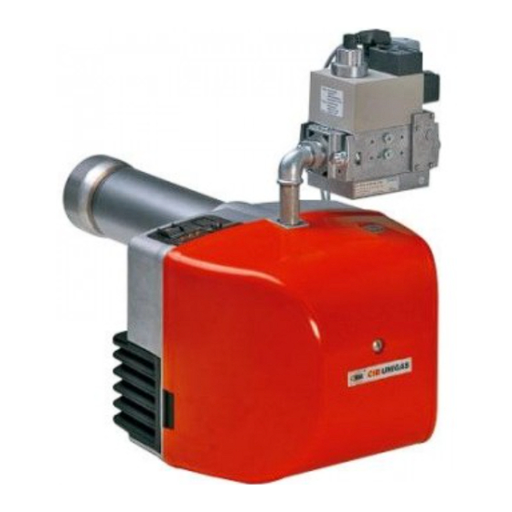
GENERAL FEATURES Burners of this series are provided with a removable cover made of ABS, a heat and crash proof plastic material. The design of the shi- fitng flange assures an efficient tightness and room saving. All the mechanical components are mounted on a removable plate that makes routine maintenance operation easier. -
Page 6: Specifications
Burner model identification Burners are identified by burner type and model. Burner model identification is described as follows. Type NG200 Model NG - Natural gas burner (1) BURNER TYPE LG - L.P.G. burner NGX - Low NOx burners M - Natural gas L - LPG (2) FUEL PR - Progressive... - Page 7 BURNERS NG200..xx..20 NG200..xx..25 LG200..xx..20 LG200..xx..25 42 - 200 Output min.- max. kW Natural gas L.P.G. Fuel Category (see next paragraph) Gas rate 4.4 - 21 1.5 - 7.7 min.-max.(Stm Gas pressure min.-max.mbar (Note2) 230V - 50 Hz Power supply 0.48 Total power Electric motor 0.18...
- Page 8 Note1: All gas flow rates are referred to Stm /h (1013 mbar absolute pressure, 15 °C temperature) and are valid for G20 gas (net calorific value H = 34.02 MJ/Stm ); for L.P.G. (net calorific value H = 93.5 MJ/Stm Note2: Maximum gas pressure = 360mbar (with Dungs MBDLE/MBC valves) Minimum gas pressure = see gas curves.
- Page 9 Overall dimensions (mm) Burner flange and boiler recommen- ded drilling template Bmin. Bmax. Cmin. Cmax. Omin Omax Tmin NG140 - (S) Ø101 Ø128 Ø108 NG140- (L) Ø101 Ø128 Ø108 NG140- (S) Ø101 Ø128 Ø108 NG140- (L) Ø101 Ø128 Ø108 NG200- (S) Ø117 Ø137 Ø108 NG200- (L)
-
Page 10: Performance Curves
Performance curves Natural gas burners LPG burners NG140 M-.xx... LG140 L-.xx... NG200 M-.xx... LG200 L-.xx... To get the input in kcal/h, multiply value in kW by 860. Data are referred to standard conditions: atmospheric pressure at 1013mbar, ambient temperature at 15°C. NOTE: The performance curve is a diagram that represents the burner performance in the type approval phase or in the laboratory tests, but does not represent the regulation range of the machine. - Page 11 Pressure/rate in the network curves Natural gas Burners Natural gas BurnersLPG burners NG140 M-.xx... LG140 L-.xx... Gas rate Stm Gas rate Stm NG200 M-.xx... LG200 L-.xx... Gas rate Stm Gas rate Stm To get the input in kcal/h, multiply value in kW by 860. Data are referred to standard conditions: atmospheric pressure at 1013mbar, ambient temperature at 15°C.
- Page 12 Caution: the gas rate value is quoted on the x-axis, the related network pressure is quoted on the y-axis (pres- sure value in the combustion chamber is not included). To know the minimum pressure at the gas train inlet, necessary to get the requested gas rate, add the pressure value in the combustion chamber to the value read on the y-axis.
- Page 13 MOUNTINGS AND CONNECTIONS Packing The burners are dispatched in cardboard packages whose dimensions are: Standard Blast tube: 600mm x 370mm x 400mm (L x P x H) Extended Blast tube: 750mm x 370mm x 400mm (L x P x H) ...
-
Page 14: Installing The Gas Train
Matching the burner to the boiler The burners described in this manual have been tested with combustion chambers that comply with EN676 regulation and whose dimensions are described in the diagram . In case the burner must be coupled with boilers with a combustion chamber smaller in dia- meter or shorter than those described in the diagram, please contact the supplier, to verify that a correct matching is possible, with respect of the application involved. -
Page 15: Mounting Positions
fasten all the items by means of screws, according to the next diagrams, observing the mounting direction for each item. NOTE: the bellow joint, the manual valve and the gaskets are not part of the standard supply. The procedures of installation fo the gas valves are showed in the next paragraph. ATTENTION: once the gas train is mounted according to the diagram, the gas proving test mus be performed, according to the procedure set by the laws in force. -
Page 16: Electrical Connections
When wishing to monitor the test, install a pressure gauge ranged to that of the pressure supply point PA (Fig. 8). If the test cycle is satisfactory, after a few seconds the consent light LC (yellow) comes on. In the opposite case the lockout light LB (red) comes on. To restart it is necessary to reset the appliance by pressing the illuminated pushbutton LB. - Page 17 BURNER IN LOW FLAME SIGNALLING LAMP LOW FLAME TIME METER FAN MOTOR HIGH FLAME TIME METER THERMOSTATS O PRESSURE SWITCHES SERIE FAN MOTOR LINE FUSE HIGH LOW FLAME THERMOSTAT/PRESSURE SWITCH LINE FUSE SAFETY THERMOSTAT/PRESSURE SWITCH BURNER LINE SWITCH CONN-MOTORE FAN MOTOR CONNECTOR FAN MOTOR LINE SWITCH CONN-LINEA BURNER POWER SUPPLY CONNNECTOR FAN MOTOR CONTACTOR...
- Page 18 Power supply without neutral If the power supply to the burner is 230V phase-phase (without the neutral wire), with the Siemens LME.. control box, between the ter- minal 2 on the board and the earth terminal, an RC Siemens RC466890660 filter must be inserted. C - Capacitor (22nF/250V) R - Resistor (1Mohm) (***) RC466890660 - RC Siemens filter...
- Page 19 ADJUSTING THE AIR AND GAS FLOW RATES Combustion head pressure curves vs. the gas flow rate Curves are referred to pressure= 0mbar in the combustion head! The curves referred to the gas pressure in the combustion head, depending on the gas flow rate, are referred to the burner in the com- bustion stage (percentage of residual O in the flues as shown in the “Recommended combustion values”...
- Page 20 Pressure in combustion head - gas flow rate curves Natural gas Burners L.P.G. Burners NG140 LG140 Gas rate Stm Gas rate Stm NG200 LG200 Gas rate Stm Gas rate Stm Low NOx burners NGX120 NGX200...
- Page 21 Setting gas and air flow rate To perform the adjustments, unscrew the fixing screws and remove the burner cover. ATTENTION: before starting the burner up, be sure that the manual cutoff valves are open and check that the pres- sure upstream the gas train complies the value quoted on paragraph “Technical specifications”. Be sure that the mains switch is closed.
-
Page 22: Adjustment Procedure
Adjustments - brief description Adjust the air and gas flow rates at the maximum output (“high flame”) first, by means of the air damper and the adjusting cam respec- tively. Check that the combustion parameters are in the suggested limits. ... - Page 23 bustion head moved. Fig. 13 - Head in “fully-ahead position” Fig. 14 - Head in “fully-backward position” Fig. 12 nce the combustion head is adjusted, remove the actuator cover (except single-stage models) and set it to the ignition position, (ignition position= 0° on the air damper index ID); The comburent air adjustment must be performed by means of the actuator.
- Page 24 Fully modulating burners To adjust the air rate in low flame and in the intermediate points, proceed as follow. Keep pushed for 5 seconds the EXIT button on the modulator (page 26); when the LED with the hand symbol lights up, push the arrow button, driving the actuator to the maximum opening position progressively;...
- Page 25 Gas Proving System VPS504 (Option) The VPS504 check the operation of the seal of the gas shut off valves. This check, carried out as soon as the boiler thermostat gives a start signal to the burner, creates, by means of the diaphragm pump inside it, a pressure in the test space of 20 mbar higher than the supply pressure.
- Page 26 Adjusting the air and gas pressure switches The air pressure switch locks the control box if the air pressure is not the one requested. If it happens, unlock the burner by means of the control box unlock pushbutton, placed on the burner control panel. The gas pressure switches check the pressure to avoid the burner operate when the pressure value is not in the requested pressure range.
-
Page 27: Operation
PART II: OPERATION PART II: OPERATION LIMITATIONS OF USE THE BURNER IS AN APPLIANCE DESIGNED AND CONSTRUCTED TO OPERATE ONLY AFTER BEING CORRECTLY CONNEC- TED TO A HEAT GENERATOR (E.G. BOILER, HOT AIR GENERATOR, FURNACE, ETC.), ANY OTHER USE IS TO BE CONSIDE- RED IMPROPER AND THEREFORE DANGEROUS. -
Page 28: Routine Maintenance
PART III: MAINTENANCE PART III: MAINTENANCE At least once a year carry out the maintenance operations listed below. In the case of seasonal servicing, it is recommended to carry out the maintenance at the end of each heating season; in the case of continuous operation the maintenance is carried out every 6 months. - Page 29 PART III: MAINTENANCE Removing the filter in the MULTIBLOC DUNGS MB-DLE 415 - 420 B01 1” 1/2 - 2” Check the filter at least once a year! Change the filter if the pressure difference between pressure connection 1 and 2 (Fig. 25-Fig. 26) p> 10 mbar. ...
- Page 30 PART III: MAINTENANCE LOCKED UNLOCKED Fig. 29 Fig. 30 Fig. 28 Fig. 33 Fig. 32 Fig. 31 Removing the combustion head ATTENTION: avoid the ignition and detection electrodes to get in touch with metallic parts (blast tube, head, etc.), otherwise the boi- ler’s operation would be compromised.
- Page 31 PART III: MAINTENANCE reassemble all the items in the reversed order, observing the electrodes position (see next paragraph) Correct electrodes positioning To get a good ignition, it is necessary to observe the measures shown in the next pictures. Be sure to fasten the electrodes fixing screw VE, before reassembling the burner.
-
Page 32: Seasonal Stop
PART III: MAINTENANCE Checking the detection current If the burner locks, execute the following inpesctions. To measure the detection signals refer to the diagrams in the following picture. If the signal is less than the value shown, check the position of the detection electrode, the electrical contacts and if necessary replace the detection electrode. -
Page 33: Troubleshooting
TROUBLESHOOTING TROUBLE CAUSE MAIN SWITCH OPEN LACK OF GAS MAXIMUM GAS PRESSURE SWITCH DEFECTIVE (IF PROVIDED) THERMOSTATS/PRESSURE SWITCHES DEFECTIVE OVERLOAD TRIPPED INTERVENTION AUXILIARIES FUSE INTERRUPTED CONTROL BOX FAULTY ... -
Page 34: Burner Exploded View
BURNER EXPLODED VIEW POS. DESCRIPTION POS. DESCRIPTION... - Page 35 PART III: MAINTENANCE FLANGE 11.3 IGNITION TRANSFORMER FLANGE 11.4 PLATE STANDARD BLAST TUBE 11.5 PRINTED CIRCUIT BOARD COVER 12.1 FAIRLEAD GAS VALVE GROUP 12.3.1 STANDARD COMBUSTION HEAD CONTROL BOX 12.3.2 DETECTION ELECTRODE BURNER HOUSING 12.3.3 IGNITION ELECTRODE AIR INTAKE 12.4 IGNITION CABLE 12.5 DETECTION CABLE...
- Page 36 APPENDIXAPPENDIX Status Color code Color SIEMENS LME11/21/22 CONTROL BOX Undervoltage Yellow - red z S z S z S z S z S The series of equipment LME.. is used for the starup and supervisione of 1- or 2- stage gas burners. The series LME..is interchangeable with the Fault, alarm S........
- Page 37 LME11 control sequence LME22 control sequence B´ B´ SB / R W / GP SB / R W / GP (LR) BV2 7101d02/0606 LME21 control sequence B´ SB / R W / GP Control sequence Waiting time Purge time TSA Ignition safety time Preignition time Postignition time (LR) BV2...
- Page 38 LME11 connection diagram Connection diagram Error message (alarm) Fuel valve PC control RESET EK2 Remote lockout reset button Flame signal Gas pressure switch Air pressure switch Load controller K2/1 K2/2 Fan motor Control thermostat/pressurestat R / W Safety limit thermostat Limit thermostat /pressure switch Ignition transformer 7101 24 /0606...
- Page 39 CONTROL PROGRAM IN THE EVENT OF FAULT In the event of lockout, the LME.. remains locked and the red signal lamp (LED) will light up.The burner control can immediately be reset. This state If a fault occurs, all outputs will immediately be deactivated (in less is also mantained in the case fo mains failure.
- Page 40 C.I.B. UNIGAS S.p.A. Via L.Galvani, 9 - 35011 Campodarsego (PD) - ITALY Tel. +39 049 9200944 - Fax +39 049 9200945/9201269 web site: www.cibunigas.it - e-mail: cibunigas@cibunigas.it Note: Specifications and data subject to change. Errors and omissions excepted.
Need help?
Do you have a question about the LG140 Series and is the answer not in the manual?
Questions and answers