Hanna Instruments HI6221 Instruction Manual
Advanced ph and orp benchtop meter
Hide thumbs
Also See for HI6221:
- Instruction manual (84 pages) ,
- Quick reference manual (2 pages) ,
- Quick reference manual (2 pages)

Related Manuals for Hanna Instruments HI6221


Summary of Contents for Hanna Instruments HI6221
- Page 1 INSTRUCTION MANUAL HI6221 Advanced pH and ORP Benchtop Meter Hanna Instruments Inc., 584 Park East Drive, Woonsocket, RI 02895 USA www.hannainst.com...
-
Page 2: Table Of Contents
All rights are reserved. Reproduction in whole or in part is prohibited without the written consent of the copyright owner, Hanna Instruments Inc., Woonsocket, Rhode Island, 02895, USA. Hanna Instruments reserves the right to modify the design, construction, or appearance of its products without advance notice. -
Page 3: Preliminary Examination
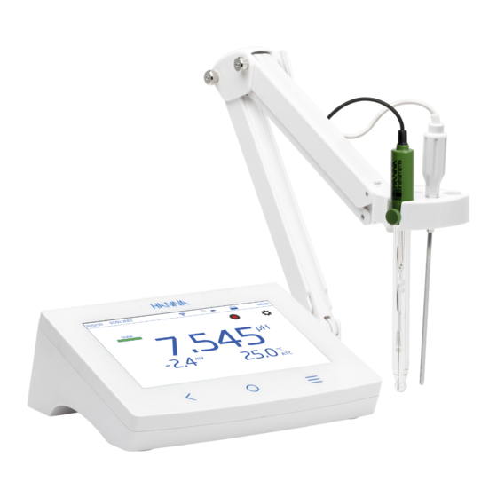
Preliminary Examination 1. PRELIMINARY EXAMINATION ® HI6221 is Hanna’s advanced benchtop pH and ORP meter with a large touch screen display and streamlined design. Each HI6221 is supplied with: • HI1131B pH electrode • HI7662-TW temperature probe • pH calibration starter kit consisting of: pH 4.01 buffer solution (2 sachets) -
Page 4: User Interface - Icons
User Interface – Icons 3. USER INTERFACE – ICONS Capacitive keys Description Back – return to a previous hierarchical menu level Home – access to measurement screen & configured profile Menu – access to Users, System Settings, Measurement Settings, Log Recall, Help Main menu Description Users –... - Page 5 User Interface – Icons Log recall Description Table view, function active/not selected Graph view, function active/not selected Information view, function active/not selected General Description Profile Background operation in progress Alarm enabled Stability / Autohold indicator Unstable Stable Autohold Active buffer selection during manual or semiautomatic calibration Forward / backward navigation, sequence of steps (gray icon: function not available) Calibration procedure, buffer selection, tutorial sequence of steps...
-
Page 6: General Description & Intended Use
4. GENERAL DESCRIPTION & INTENDED USE HI6221 is an advanced benchtop meter with a capacitive display, comprised of a housing and an integrated pH/ORP measurement module. Compact and easy to operate, the meter is delivered with Hanna Instruments HI1131B combination pH electrode and HI7662-TW temperature probe for pH measurement. -
Page 7: Main Features
General Description & Intended Use 4.1. MAIN FEATURES Measurement & Calibration • Measure pH/mV (pH) or mV/Rel.mV (ORP) with temperature • Application-specific profiles allow quick and direct measurement without the need to update the sensor and system settings • Active log during measurement •... -
Page 8: Specifications
Specifications 5. SPECIFICATIONS 5.1. INSTRUMENT −2.0 to 20.0 pH Range* −2.00 to 20.00 pH −2.000 to 20.000 pH 0.1 pH Resolution 0.01 pH 0.001 pH ±0.1 pH ±0.01 pH Accuracy ±0.002 pH (±1 last significant digit) Range −2000.0 mV to 2000.0 mV 1 mV Resolution 0.1 mV... - Page 9 9 Specifications Temperature user calibration 1 point, adjustable Measurement pH: pH measurement and pH mV mV: measurement Basic Rel.mV: measurement, Absolute mV Temperature (ATC or MTC) Measurement profile (when enabled) Stability status Basic view information pH last calibration date, electrode offset, average slope, and pH views Simple GLP electrode condition (for 24 hours after calibration)
-
Page 10: Electrodes
Specifications 5.2. ELECTRODES HI1131B – pH electrode Range 0 to 13 pH Reference cell type Double, Ag/AgCl Ceramic Junction type Single 15-20 µL per h Refill electrolyte 3.5M KCl Maximum pressure 0.1 bar Body material Glass Tip shape Spheric (Ø 9.5 mm) Operating temperature −5 to 100 °C (23 to 212°F) –... -
Page 11: Functional & Lcd Description
11 Functional & LCD Description 6. FUNCTIONAL & LCD DESCRIPTION 6.1. MAIN UNIT Front View 1. LCD display 3. Home key 2. Back key 4. Menu key LCD Description 1. Current time 9. Buffer trays 2. Current date 10. Temperature reading and temperature compensation status 3. - Page 12 Functional & LCD Description Status Area Continuously displayed after powering the unit, status area runs horizontally across the top of the LCD screen. • Top left – current time & date • Middle – connectivity status • Top right – storage space availability & username Direct Keys Icon Name...
-
Page 13: Electrodes
13 Functional & LCD Description 6.2. ELECTRODES HI1131B HI7662-TW pH electrode Temperature probe 1. Reference wire 2. Inner reference junction 1. Cable 3. Reference fill cap 2. Handle 4. Outer reference junction 3. Stainless steel tube 5. Glass bulb... -
Page 14: Getting Started
Getting Started 7. GETTING STARTED 7.1. ATTACHING THE ELECTRODE ARM Attaching the electrode holder base plate • Take the HI764060 electrode arm from the box. • Identify the metal base plate (4) with the integrated pivot pin (5) and the screw (2). •... -
Page 15: Using The Electrode Holder
15 Getting Started To reattach the clip onto the electrode arm: Insert clip 1. Align the clip’s dovetail over the slot. 2. Gently push down to slide in position. Using the adapter The electrode arm is ended with an electrode holder. The holder is fitted with an adapter with three different-sized apertures: Adapter for pH probe center positioning •... -
Page 16: Language & Regional Preferences
• Analog pH or ORP electrode with BNC connector (non-amplified or non-digital) • pH or ORP half-cell sensors and separate reference electrodes with suitable jack connectors • Hanna Instruments pH electrodes with integral temperature elements. See Accessories, Electrodes section. Connecting a USB-A keyboard Connect a USB’s keyboard plug into the USB-A input on the back of the unit. -
Page 17: Basic Operations
17 System Menu Items To configure regional preferences, from Tutorial screen: • Tap (direct Menu key) to access System Menu screen. • Tap (System Settings icon) and select System tab. Users can change the date, time, and region settings, as well as language preferences. 7.5. -
Page 18: Users
System Menu Items 8.1. USERS Users is the first item under the System Menu and enables multiple-users configuration, rights management, and account creation. On first access, “Admin” is used as default user name and no password is required. Default options are updated from the Users menu. - Page 19 19 System Menu Items 6. Tap Logout to enter Users screen. “Admin” account is automatically created (default). 7. Tap the plus symbol avatar. 8. Input user name and tap 9. Enter password and tap . Reenter password to confirm. Log Out & Switch User 1.
- Page 20 System Menu Items Account Management Users with administrator rights are able to: • Enable Account Creation • Enable Logins Each power up requires user selection before instrument enters measurement mode. • Enable Admin i.e. assign administrator rights to a standard user • Reset Password 1.
-
Page 21: System Settings
21 System Menu Items 8.2. SYSTEM SETTINGS System Settings is the second item under the System Menu. Network, Connect & Print, System tabs permit users to navigate system settings and operations, configure network connection and architecture, connectivity and printing services, change system settings, and view meter information. System Settings overview Disabled IP Address... - Page 22 System Menu Items Network Data sharing options: Ethernet, Wi-Fi, or Disabled With connection established, IP assignment can be set as: • Dynamic – IP Address, Gateway, Netmask, DNS Server are auto assigned • Static – network details are filled in manually To fill in network information: 1.
- Page 23 23 System Menu Items Printer Options: Network, USB Printer, Flash Drive • Select Network to connect a printer in the same network. Tap to enter IP address. • Select USB Printer to connect a printer via USB-A port. • Select Flash Drive to export log files directly to USB Flash Drive. •...
- Page 24 System Menu Items System Options: Time, Date, Language, Meter ID, Decimal Separator, Backlight Saver, Beepers, Startup Tutorial, Factory Settings, Reset User Note: Use the scroll bar to view or select from entire settings list. Time & Date to enable (or disable): • Set Automatically (meter must be connected to the internet) ` Direct selection from scrollable list of options ` UTC options: from UTC 00:00 to UTC+14:00...
- Page 25 25 System Menu Items to save. or corresponding tab to enable (or disable) following settings: • Decimal Separator: comma or period • Backlight Saver: enabled, 1 to 60 minutes (or disabled) If the backlight turns off after the set period of time, tap to turn it back on. •...
-
Page 26: Measurement Settings
System Menu Items Note: Option available to users with administrator rights only. Reset User Option restores default settings for this user. All data (including profiles and log files) specific to this user will be permanently deleted, except for the username and password. When option invoked, the instrument asks for confirmation. - Page 27 27 System Menu Items Measurement Settings Overview Calibration, Reading, Temperature, View, Alarms, Logging, Profile tabs help user navigate through all measurement operations. The following table presents an overview of possible functions. Calibration Rel.mV Last Calibration Calibrate Calibrate Clear Clear Automatic Buffer Entry Type Semiautomatic Manual Enabled...
- Page 28 System Menu Items View Rel.mV Basic Basic Basic Simple GLP Simple GLP View Type Full GLP Graph Graph Graph Table Table Table Alarms Rel.mV −2.000 to 20.000 High / Low pH High / Low mV −2000.0 to 2000.0 −20.0 to 120.0 °C High / Low Temperature −4.0 to 248.0 °F 253.2 to 393.2 K...
-
Page 29: Log Recall
29 System Menu Items 8.4. LOG RECALL Log Recall is the forth item under the System’s Menu and allows data selection, viewing, sharing, and deletion. Logged data is retrieved by the user that has logged the measurement. • Data is stored in parameter-specific .CSV files: pH, mV, and Rel.mV. •... - Page 30 System Menu Items 4. Tap icon to have logged data displayed in tabulated form or plotted. 5. Tap icon and scroll through USER, LOG, INSTRUMENT, CHANNEL, GLP DATA information.
- Page 31 31 System Menu Items Select (Deselect) All To export to a USB-A flash drive: 1. Tap (Log Recall) to access the log history. 2. Tap Select All button to select entire log history. With all files selected, tap Delete to empty the log or tap Share to transfer data. 3.
- Page 32 System Menu Items HI6221 can act as an FTP server (host) or client. Meter has to be connected to the internet and Allow FTP access to meter enabled. • Use meter’s IP address and password to connected and view logged files. • Enter in the FTP dedicated fields own server information to export logged files to the FTP server.
- Page 33 33 System Menu Items 5. Click Next. 6. In the Binding and SSL Settings window keep all default settings but change the SSL option to No SSL. 7. Click Next. 8. When prompted to authenticate and authorize information, select Basic and Specified users. 9.
- Page 34 System Menu Items Print • Connect either a printer (Network or USB) or plug-in a USB Flash Drive (see System Settings, Connect & Print section). • Tap Print and follow on-screen instructions. Web server Any browser can be used to access the web server and download log files. Meter has to be connected to the internet and Enable meter web server enabled (see System Settings, Connect &...
-
Page 35: Help
35 System Menu Items 8.5. HELP Help is the fifth item under the System Menu. • Tap to access support and navigate through an overview of system’s main functionalities. • Tap to play (stop) video-supported segments: ` 1.5. Setting up the device ` 3.1. -
Page 36: Measurement & Electrode Setup Menu
Measurement & Electrode Setup Menu 9. MEASUREMENT & ELECTRODE SETUP MENU From the Measurement screen, tap to access system and measurement configuration tabs. Alternatively, tap (Menu key) then tap 9.1. CALIBRATION Options: Last Calibration, Buffer Entry Type, Buffer Auto Confirmation, First Calibration Point, Calibration Reminder, Buffer Group Last Calibration: calibrate or clear a previous calibration Buffer Entry Type •... - Page 37 37 Measurement & Electrode Setup Menu “Calibrate probe” message runs along the bottom of the measurement screen if calibration is not done within set interval. Buffer Group Option used for Automatic calibration. To move from Available Standard/Custom Buffers to the Buffers in Use column (up to five buffers), select buffer and forward arrow.
-
Page 38: Reading
Measurement & Electrode Setup Menu 9.2. READING Options: Parameter, Resolution, Stability Criteria, Reading Mode Parameter Options: pH, mV, Rel. mV Tap to select desired measurement configuration: pH, mV (ORP), Rel. mV (ORP with calibration). Resolution Tap to select measurement resolution based on selected parameter. Stability Criteria Set the stability criterion for selected mode based upon selected stability setting. -
Page 39: Temperature
39 Measurement & Electrode Setup Menu ` When stable, the indicator stops blinking and measurement freezes at current value. ` Tap to return to direct measurement. 9.3. TEMPERATURE Options: Temperature Source, Temperature Unit, Manual, Isopotential Point (pH parameter only), User Temperature Calibration Temperature Source: Automatic, Manual User can select between physical temperature input source (Automatic) and entering sample temperature value manually (Manual). - Page 40 Measurement & Electrode Setup Menu Temperature Unit: Celsius, Fahrenheit, Kelvin degrees • Tap to select unit. Manual To manually input value (Manual selected under Temperature Source or no temperature probe): 1. Select temperature unit. 2. Tap on Manual Temperature field. Use the on-screen keypad to enter sample’s temperature. Isopotential Point: −2.000 pH to 20.000 pH Isopotential point is the point at which temperature has no effect on pH readings.
-
Page 41: View
41 Measurement & Electrode Setup Menu 9.4. VIEW pH: Basic, Simple GLP, Full GLP, Graph, Table mV: Basic, Graph, Table Rel.mV: Basic, Simple GLP, Graph, Table • Select preferred display configuration from View Type window. Basic Screen displays the measured value, measurement unit as well as temperature-probe status. - Page 42 Measurement & Electrode Setup Menu Simple GLP In addition to data displayed when Basic option is selected, screen displays: last calibration date and time, Offset value, average slope (Avg.Slope), and electrode condition (Condition). Note: If no calibration has been made, Not Calibrated is displayed. Full GLP In addition to data displayed when Simple GLP option is selected, screen displays: electrode symbol, used buffers trays as well as calibration date, time, and temperature probe status.
-
Page 43: Alarms
43 Measurement & Electrode Setup Menu Table When Table is selected, the measured values are displayed tabulated (complete with date, time, and notes made during logging). The newest data is displayed on the top of the table. 9.5. ALARMS Options pH: High or Low pH, High or Low Temperature mV &... -
Page 44: Logging
Measurement & Electrode Setup Menu To set an alarm limit: 1. Tap to enable low or high threshold option. 2. Use the on-screen keypad to enter the value. 3. Tap Enter to confirm or Cancel to exit and return to measurement setting options. (alarm icon) is displayed on the measurement screen when an alarm is active. 9.6. - Page 45 45 Measurement & Electrode Setup Menu Logging Type • Automatic Data is logged automatically at predefined time intervals (i.e. Sampling Period). A file name is automatically generated, complete with year/month/day, and logging time. Files are identified by parameter e.g.: • pH log files: 20220329_085101-pH_auto.CSV •...
-
Page 46: Profiles
Measurement & Electrode Setup Menu Log Note & Log Info Notes on measured data are saved together with logged data. Sample ID Manual and autohold samples can be labeled with a numerical ID (increments with each new sample logged), a text label, or a text label with numerical ID. With Increment selected: 1. -
Page 47: Calibration Procedure
47 Calibration procedure Load Profile To select from list of predefined profiles: 1. Tap to select from the Load Profile list. 2. Profile name is automatically entered in the Current Profile field. 3. Start measuring. 10. CALIBRATION PROCEDURE Calibration Overview (compiled UI symbols) Calibration type Forward or backward navigation, sequence of steps Save and Confirm buffers, calibration procedure... -
Page 48: Ph Calibration
Selecting Buffers in Use, Standard or Custom (navigation guidelines) In addition to selecting from 8 standard options, users can define 5 custom buffers to be used for calibration. HI6221 automatically recognizes the closest buffer to the pH value being measured from all available (standard and custom) buffers. - Page 49 49 Calibration procedure 6. For custom values, tap an empty tray to input a new value or an existing tray to edit. Follow the Editing Custom Buffers Values steps. Editing Custom Buffer Values (navigation guidelines) With Calibration tab selected: 1. Tap Edit next to Buffer Group. 2.
- Page 50 Calibration procedure 4. Use the numeric keypad to enter a value. 5. Tap or tap Save to confirm (Cancel to return without applying changes). 6. Tap on tray with newly-entered custom value. A rectangular outline confirms that buffer can be transferred to Buffers in Use. 7.
- Page 51 The procedure is the same as Automatic Calibration. Manual Calibration With this option selected, the HI6221 uses from all available buffer values (standard and custom). 1. Tap Calibration tab. 2. Tap to select Manual calibration type.
-
Page 52: Relative Mv Calibration
Calibration procedure 10.2. RELATIVE mV CALIBRATION The Rel. mV calibration or ORP calibration allows the user to: • Perform a single point, custom calibration (Rel. mV). • Restore the factory calibration (Clear Calibration). The Oxidation-Reduction Potential (ORP), displayed in mV, is the voltage that results from the difference in potential between the platinum (or gold) ORP sensor and the silver/silver chloride reference electrode. -
Page 53: Measurement
53 Measurement 2. Place ORP electrode tip into a beaker of standard or a sample with known value. HI7021 (ORP solution for platinum and gold electrodes) reads 240 mV at 25°C, HI7022 (ORP test solution for platinum and gold electrodes) reads 470 mV at 25 °C. 3. -
Page 54: Direct Readings
Measurement 8. If measuring across a temperature gradient, allow the sensor to reach thermal equilibrium. If using manual temperature compensation input the sample temperature. 9. Once the reading indicates Stable, record measurement data. 10. Remove the electrodes from the sample, repeat steps 3, 4 and then place into the next rinse, then test sample. -
Page 55: Logging
55 Logging The measured value is kept on display and stops blinking. Autohold • To return to direct Reading Mode, tap (pH icon). 12. LOGGING Three logging types are available: Automatic, Manual, and Autohold. Automatic logging • Readings are logged (tap ) at predefined time intervals. -
Page 56: Automatic Logging
Logging Autohold logging • Readings are logged each time is tapped and configured stability criteria is reached. • All Autohold readings are stored in a single log (i.e. records made on different days are logged in the same log). Note: Stability criteria can be set to Fast, Medium, or Accurate for all logging types. 12.1. -
Page 57: Autohold Logging
57 Maintenance & Conditioning 12.3. AUTOHOLD LOGGING 1. From Measurement screen, tap (Measurement Menu). 2. Tap Reading tab to select stability criteria (Accurate, Medium, or Fast). Note: Autohold logging uses this criteria for logging. Setting this will affect when data is recorded. 3. - Page 58 Storage solution for at least 1 hour, rinse with water, and calibrate before using. General Cleaning of HI6221 The following steps outline the process to ensure users keep the benchtop clean and disinfected while limiting the risk of damage from unsuitable cleaners.
-
Page 59: Error Messages
59 Error Messages 14. ERROR MESSAGES The instrument shows clear warning messages (refer to the instrument’s on-display message area, bottom of the screen) when erroneous conditions appear, when measured values are outside the expected range, while logging, for invalid high / low temperature alarm value as well as invalid low / high mV Alarm value, isopotential point. The information below provides an explanation of the errors and warnings, and recommended action to be taken. -
Page 60: Accessories
Accessories 15. ACCESSORIES pH BUFFER CALIBRATION SOLUTIONS HI6016 Millesimal calibration buffer pH 1.679 (500 mL) HI6003 Millesimal calibration buffer pH 3.000 (500 mL) HI6004 Millesimal calibration buffer pH 4.010 (500 mL) HI6068 Millesimal calibration buffer pH 6.862 (500 mL) HI6007 Millesimal calibration buffer pH 7.010 (500 mL) HI6010 Millesimal calibration buffer pH 10.010 (500 mL) - Page 61 61 Accessories ELECTRODE CLEANING SOLUTIONS HI70000P Electrode rinse sachet, 25 pcs. (20 mL) HI7061L General purpose solution (500 mL) HI7073L Protein cleaning solution (500 mL) HI7074L Inorganic substance cleaning solution (500 mL) HI7077L Oil and Fat cleaning solution (500 mL) HI8061L General purpose solution (500 mL, FDA approved bottle) Protein cleaning solution (500 mL, FDA approved bottle)
- Page 62 Accessories HI1053B Glass body, triple ceramic, conical shape, refillable, combination electrode Ideally suited for emulsions. HI1083B Glass body, micro, viscolene, non refillable, combination electrode Application: biotechnology, micro titration HI1131B Glass body, refillable, double junction, combination electrode Application: general purpose HI1330B Glass body, semimicro, single junction, refillable, combination electrode Application: laboratory, vials...
- Page 63 Accessories HI1331B Glass body, semimicro, single junction, refillable, combination electrode Ideally suited for flasks. HI1230B Plastic body (PEI), double junction, gel filled, combination electrode Application: general, field HI2031B Glass body, semimicro, conical, single junction, refillable, combination electrode Application: semisolids HI1332B Plastic body (PEI), double junction, refillable, combination electrode Application: general purpose...
- Page 64 Accessories HI1413B Glass body, single junction, flat tip, viscolene, non refillable, combination electrode Application: surface measurement FC100B Plastic body (PVDF), double junction, refillable, combination electrode Application: general purpose for food industry FC200B Plastic body (PVDF), single junction, conical, viscolene, non refillable, combination electrode Application: meat and cheese FC210B Glass body, double junction, conical, viscolene, non refillable, combination electrode...
- Page 65 Accessories FC220B Glass body, triple ceramic, single junction, refillable, combination electrode Application: food processing pH with 10K NTC thermistor HI1131Y Glass body, single ceramic frit, double junction, refillable, combination electrode Application: general purpose HI1230Y PEI body, single ceramic frit, double junction, combination electrode Application: general purpose HI1048Y Glass body, CPS sleeve junction, combination electrode...
-
Page 66: Abbreviations
HI7855/3, 3 m (9.9’) long SCREW TYPE ELECTRODES METER BNC SOCKET Connector and 3.0 mm (0.12”) cable with BNC Please refer to the Hanna Instruments general catalog for more electrodes with screw-type or BNC connectors. 16. ABBREVIATIONS Automatic Temperature Compensation Comma-Separated Values... -
Page 67: Certification
If service is required, contact your local Hanna Instruments office. If under warranty, report the model number, date of purchase, serial number (see engraved on the bottom of the meter) and the nature of the problem. -
Page 68: Regulatory Notices For The Wi-Fi Module
Regulatory notices for the Wi-Fi Module REGULATORY NOTICES FOR THE WI-FI MODULE United States (FCC) FCC ID: 2ADHKATWINC1500. This device complies with Part 15 of the FCC Rules. Operation is subject to the following two conditions: (1) this device may not cause harmful interference, and (2) this device must accept any interference received, including interference that may cause undesired operation.
Need help?
Do you have a question about the HI6221 and is the answer not in the manual?
Questions and answers