Toro 03673 Reelmaster 5410-G Operator's Manual
Traction units
Hide thumbs
Also See for 03673 Reelmaster 5410-G:
- Operator's manual (48 pages) ,
- Service manual (662 pages)

Related Manuals for Toro 03673 Reelmaster 5410-G


Summary of Contents for Toro 03673 Reelmaster 5410-G
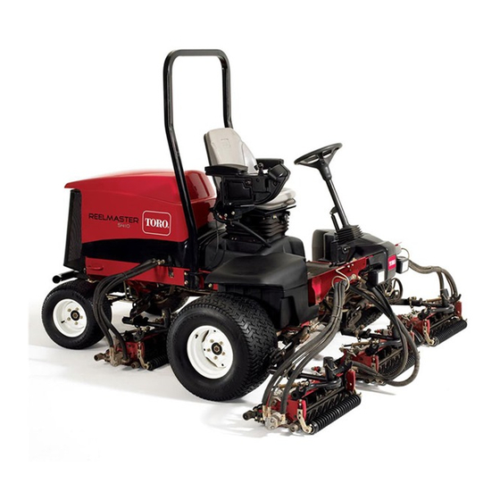
- Page 1 Form No. 3376-722 Rev B Reelmaster ® 5410-G and 5510-G Traction Units Model No. 03673—Serial No. 313000001 and Up Model No. 03689—Serial No. 313000001 and Up *3376-722* B Register at www.Toro.com. Original Instructions (EN)
-
Page 2: Introduction
You are responsible for operating the product properly and safely. You may contact Toro directly at www.Toro.com for product and accessory information, help finding a dealer, or to register your product. -
Page 3: Table Of Contents
Belt Maintenance ............41 Safety ................4 Tensioning the Alternator Belt .........41 Safe Operating Practices........... 4 Hydraulic System Maintenance ........41 Toro Riding Mower Safety ........6 Changing the Hydraulic Fluid........41 Safety and Instructional Decals ......... 7 Replacing the Hydraulic Filters .........42 Setup ................10 Checking the Hydraulic Lines and Hoses....42... -
Page 4: Safety
Preparation Safety • While mowing, always wear substantial footwear, long trousers, hard hat, safety glasses, and ear protection. Long This machine meets or exceeds CEN standard EN hair, loose clothing, or jewelry may get tangled in moving 836:1997, ISO standard 5395:1990, and ANSI B71.4-2012 parts. -
Page 5: Maintenance And Storage
• • Before attempting to start the engine, disengage all blade Keep hands and feet away from the cutting units. attachment clutches, shift into neutral, and engage the • Look behind and down before backing up to be sure of parking brake. -
Page 6: Toro Riding Mower Safety
Toro Riding Mower Safety guards can lead to thrown object injuries. Do not resume mowing until the area is cleared. The following list contains safety information specific to Toro products or other safety information that you must know that Maintenance and Storage is not included in the CEN, ISO, or ANSI standard. -
Page 7: Safety And Instructional Decals
Safety and Instructional Decals Safety decals and instructions are easily visible to the operator and are located near any area of potential danger. Replace any decal that is damaged or lost. 93-7272 1. Cutting/dismemberment—hazard, fan-stay away from moving parts. 106-6755 1. - Page 8 110-9642 1. Stored energy hazard—read the Operator's Manual. Battery Symbols 2. Move the cotter pin to the hole closest to the rod bracket and then remove the lift arm and pivot yoke. Some or all of these symbols are on your battery 1.
- Page 9 125–2924 1. Read the Operator’s Manual 121–5643 1. Read the Operator’s 3. Engine—run Manual. 2. Engine—start 4. Engine—stop 125–8754 1. Head lights 6. Slow 2. Engage 7. Lower the cutting units 3. Power take-off (PTO) 8. Raise the cutting units 4.
-
Page 10: Setup
Setup Loose Parts Use the chart below to verify that all parts have been shipped. Procedure Description Qty. – No parts required Adjust the tire pressure. – No parts required Adjust the step height. – No parts required Adjust the control arm position. Front hose guide-R.H. -
Page 11: Adjusting The Control Arm Position
Figure 2 1. Step 2. Step brackets Figure 3 1. Control arm 3. Bolts (2) 2. Raise or lower the step to the desired height and 2. Retaining brackets re-secure the brackets to the frame with the 2 bolts and nuts. 2. - Page 12 Figure 6 1. Opposite carrier frame tab 2. Rod bracket D. Mount the rod bracket to the cutting unit tabs with the carriage bolts and nuts (Figure 6). Important: On the #4 (left front) and #5 (right front) cutting units (Figure 7), use the rod bracket mounting nuts to install the hose guides to the front of the cutting unit Figure 4...
- Page 13 g019284 Figure 9 1. Hose guides (each must lean toward the center cutting unit) Note: When installing or removing the cutting units, make sure the hairpin cotter is installed in the spring rod hole next to the rod bracket. When not installing or removing the cutting units, the hairpin cotter must be installed in the hole in the end of the rod.
-
Page 14: Adjusting The Turf Compensation Spring
B. Insert the lift arm yoke onto the carrier frame shaft (Figure 11). C. Insert the lift arm shaft into the lift arm and secure it with the washer and lynch pin (Figure 12). 10. Insert the cap over the carrier frame shaft and lift arm yoke. -
Page 15: Using The Cutting Unit Kickstand
Figure 15 1. Turf compensation spring 3. Spring rod 2. Hair pin cotter 4. Hex nuts Figure 16 1. Cutting unit kickstand 2. Tighten the hex nuts on the front end of the spring rod until the compressed length of the spring is 12.7 cm (5 inches) on Reelmaster 5410, 5 inch cutting units Secure the kickstand to the chain bracket with the snapper or 15.9 cm (6.25 inches) on Reelmaster 5510, 7 inch... -
Page 16: Product Overview
Product Overview speed, fully press the pedal while the engine speed setting is in the Fast position. To stop, reduce foot pressure on the traction pedal and allow it to return to the center position. Figure 18 1. Engine hood 5. -
Page 17: Key Switch
increments. By holding the switch down the engine will automatically move to High or Low idle, depending on which end of the switch is depressed. G021208 Figure 21 g021209 1. Lower mow/raise control 4. Enable/disable switch lever 2. Key switch 5. - Page 18 InfoCenter Icon Description SERVICE DUE Indicates when scheduled service should be performed Engine RPM/status—indicates the engine RPM Hour meter Info icon Fast Slow Figure 24 1. Power point Fuel level Using the InfoCenter LCD Display Raise cutting units The InfoCenter LCD display shows information about your machine such as the operating status, various diagnostics and other information about the machine (Figure 25) There Lower cutting units...
- Page 19 Faults The Faults menu contains a list of the recent machine CAN bus faults. Refer to the Service Manual or your Authorized Toro Distributor for more InfoCenter information on the Faults menu and the information contained there. Bad or failed...
- Page 20 Engine Run Indicates the inputs, qualifiers Machine Controller Revision Lists the software revision of and outputs for starting the the master controller. engine. InfoCenter Revision Lists the software revision of Backlap Indicates the inputs, qualifiers the InfoCenter. and outputs for operating the CAN Bus Lists the machine backlap function.
- Page 21 To Set the Blade Count • In the Settings Menu, scroll down to Blade Count • Press the right button to change the blade count between 5, 8 or 11 blade reels. To Set the Mow Speed • In the Settings Menu, scroll down to Mow Speed. •...
-
Page 22: Specifications
A selection of Toro approved attachments and accessories is available for use with the machine to enhance and expand its capabilities. Contact your Authorized Service Dealer or Distributor or go to www.Toro.com for a list of all approved attachments and accessories. -
Page 23: Operation
Change the type of engine oil according to the ambient temperature. Clean debris off of the screen, oil cooler, and front of the Toro Premium Engine oil is available from your distributor in radiator daily and more often if conditions are extremely either 15W-40 or 10W-30 viscosity. -
Page 24: Adding Fuel
DANGER In certain conditions, fuel is extremely flammable and highly explosive. A fire or explosion from fuel can burn you and others and can damage property. • Fill the fuel tank outdoors, in an open area, when the engine is cold. Wipe up any fuel that spills. •... -
Page 25: Checking The Hydraulic Fluid
19 liter (5 gallon) pails or 55 gallon drums. See parts catalog or Toro distributor for part numbers.) Alternate fluids: If the Toro fluid is not available, other fluids may be used provided they meet all the following material properties and industry specifications. We do not recommend the use of synthetic fluid. -
Page 26: Checking The Reel To Bedknife Contact
Checking the Reel to Bedknife blade count, mow speed and HOC, but the new value will also be displayed. Contact Note: The reel speed may need to be increased or Each day before operating, check reel to bedknife contact, decreased to compensate for varying turf conditions. regardless if the quality of cut had previously been acceptable. -
Page 27: Pushing Or Towing The Machine
3. Loosen the switch mounting screws (Figure 31) and move the switch down to increase the lift arm turn around height or move the switch up to decrease the lift arm turn around height. Tighten the mounting screws. Figure 32 1. -
Page 28: Tie Downs
Tie Downs (Figure 36). When the machine is functioning properly and the key switch is moved to the On/Run position, the • Front—the hole in the rectangular pad, under the axle diagnostic light will turn on briefly to indicate the light tube, inside each front tire (Figure 34). -
Page 29: Hydraulic Valve Solenoid Functions
Operating Tips 4. Individually, change each of the switches from open to closed (i.e., sit on seat, engage traction pedal, etc.), and note that the appropriate state of the switch changes. Familiarization Repeat this for all switches that you can change by hand. -
Page 30: Maintenance
Maintenance Note: Determine the left and right sides of the machine from the normal operating position. Recommended Maintenance Schedule(s) Maintenance Service Maintenance Procedure Interval • Torque the wheel lug nuts to 94 to 122 N-m (70 to 90 ft-lb). After the first hour •... -
Page 31: Daily Maintenance Checklist
Daily Maintenance Checklist Duplicate this page for routine use. For the week of: Maintenance Check Item Mon. Tues. Wed. Thurs. Fri. Sat. Sun. Check the safety interlock operation. Check the brake operation. Check the engine oil and fuel level. Check the air filter restriction indicator. Check the radiator and screen for debris. -
Page 32: Service Interval Chart
Service Interval Chart Figure 37 CAUTION If you leave the key in the ignition switch, someone could accidently start the engine and seriously injure you or other bystanders. Remove the key from the ignition before you do any maintenance. Lubrication Greasing the Bearings and •... - Page 33 • • Cutting unit carrier frame and pivot (2 each) (Figure 40) Axle steering pivot (1) (Figure 43) Figure 43 • Steering cylinder ball joints (2) (Figure 44) Figure 40 • Lift arm pivot shaft (1 each) (Figure 41) Figure 41 Figure 44 •...
-
Page 34: Engine Maintenance
Engine Maintenance Servicing the Air Cleaner Check the air cleaner body for damage which could cause an air leak. Replace if damaged. Check the whole intake system for leaks, damage or loose hose clamps. g021218 Service the air cleaner filter only when the service indicator Figure 47 (Figure 46) requires it. -
Page 35: Replacing The Spark Plugs
Figure 50 1. Air gap 5. Install the correctly gapped spark plug with gasket seal, g021213 and tighten the plug to 25 to 30 N⋅m (18 to 21.6 ft-lb). If a torque wrench is not used, tighten the plug firmly. Figure 49 1. -
Page 36: Fuel System Maintenance
Fuel System Maintenance Replacing the Fuel Filter DANGER In certain conditions, gasoline is extremely flammable and highly explosive. A fire or explosion g021236 from gasoline can burn you and others and can damage property. Figure 52 • Drain gasoline from the fuel tank when the 1. -
Page 37: Electrical System Maintenance
Electrical System Maintenance Important: Before welding on the machine, disconnect both cables from the battery, both wire harness plugs from the electronic control module, and the terminal connector from the alternator to prevent damage to the electrical system. Servicing the Battery g021219 WARNING Figure 53... -
Page 38: Drive System Maintenance
Drive System 5. Tighten the locknut to secure the adjustment. 6. Stop the engine. Remove the jack stands and lower the Maintenance machine to the shop floor. 7. Test drive the machine to make sure it does not creep. Adjusting the Traction Drive Adjusting the Rear Wheel for Neutral Toe-in... -
Page 39: Cooling System Maintenance
Cooling System Maintenance Removing Debris from the Cooling System Remove debris from the screen and radiator/oil cooler daily (clean more frequently in dirty conditions). 1. Turn the engine off and remove the key from the ignition switch. 2. Thoroughly clean all debris out of the engine area. 3. -
Page 40: Brake Maintenance
Brake Maintenance Adjusting the Parking Brake If the parking brake fails to engage, an adjustment to the brake pawl is required. Adjusting the Service Brakes 1. Loosen the 2 screws securing the parking brake pawl Adjust the service brakes when there is more than 1 inch of to the frame (Figure 60). -
Page 41: Belt Maintenance
Change hydraulic fluid after every 800 operating hours, in normal conditions. If fluid becomes contaminated, contact 1. Open the hood. your local Toro distributor because the system must be 2. Check the tension of the alternator belt by depressing flushed. Contaminated fluid looks milky or black when it, with moderate thumb pressure, midway between the compared to clean oil. -
Page 42: Replacing The Hydraulic Filters
Replacing the Hydraulic Filters The hydraulic system is equipped with a service interval indicator (Figure 63). With the engine running at operating temperature, view the indicator, it should be in the Green zone. When the indicator is in the Red zone, change the hydraulic filters. -
Page 43: Hydraulic System Test Ports
Hydraulic System Test Ports 1. Mow circuit test ports (2) Use the hydraulic system test ports to test the pressure in the hydraulic circuits. Contact your local Toro distributor for Use the test port on the lift manifold block (Figure 68) to assistance. -
Page 44: Cutting Unit System Maintenance
Cutting Unit System stabilizes, then return the reel speed to your desired speed. Maintenance 9. To make an adjustment to the cutting units while backlapping, turn the reels off by moving the Lower Mow/Raise lever rearward; the Enable/Disable switch Backlapping the Cutting Units to the Disable position, and stop the engine. -
Page 45: Storage
C. Coat the cable terminals and battery posts with 13. Thoroughly clean and service the air cleaner assembly. Grafo 112X skin-over grease (Toro Part No. 14. Seal the air cleaner inlet and the exhaust outlet with 505-47) or petroleum jelly to prevent corrosion. - Page 46 Notes:...
- Page 47 Notes:...
-
Page 48: The Toro Total Coverage Guarantee
Countries Other than the United States or Canada Customers who have purchased Toro products exported from the United States or Canada should contact their Toro Distributor (Dealer) to obtain guarantee policies for your country, province, or state. If for any reason you are dissatisfied with your Distributor's service or have difficulty obtaining guarantee information, contact the Toro importer.
Need help?
Do you have a question about the 03673 Reelmaster 5410-G and is the answer not in the manual?
Questions and answers