Toro Reelmaster 5410-D Operator's Manual
Hide thumbs
Also See for Reelmaster 5410-D:
- Operator's manual (92 pages) ,
- Service manual (662 pages) ,
- Operator's manual (64 pages)

Related Manuals for Toro Reelmaster 5410-D


Summary of Contents for Toro Reelmaster 5410-D
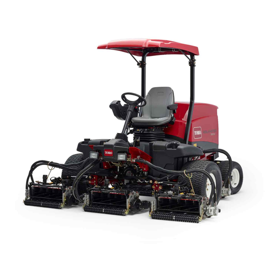
- Page 1 Form No. 3450-146 Rev B Reelmaster ® 5410-D and 5510-D Traction Unit Model No. 03606—Serial No. 410500000 and Up Model No. 03607—Serial No. 410300000 and Up *3450-146* Register at www.Toro.com. Original Instructions (EN)
- Page 2 It is a violation of California Public Resource Code additional information, contact an Authorized Service Section 4442 or 4443 to use or operate the engine on Dealer or Toro Customer Service and have the model and serial numbers of your product ready. Figure 1...
-
Page 3: Table Of Contents
Contents Fuel Pick-up Tube Screen......... 53 Electrical System Maintenance ......53 Electrical System Safety ........53 Safety ............... 4 Servicing the Battery......... 53 General Safety ........... 4 Checking the Fuses .......... 54 Engine Emission Certification ......4 Drive System Maintenance ........54 Safety and Instructional Decals ...... -
Page 4: Safety
Safety This machine has been designed in accordance with EN ISO 5395 (when you complete the setup procedures) and ANSI B71.4-2017. General Safety This product is capable of amputating hands and feet and of throwing objects. • Read and understand the contents of this Operator’s Manual before starting the engine. -
Page 5: Safety And Instructional Decals
Safety and Instructional Decals Safety decals and instructions are easily visible to the operator and are located near any area of potential danger. Replace any decal that is damaged or missing. decal106-6754 decalbatterysymbols 106-6754 Battery Symbols 1. Warning—do not touch the hot surface. Some or all of these symbols are on your battery 2. - Page 6 decal110-8921 110-8921 1. Traction unit speed 2. Slow 3. Fast decal110-9642 110-9642 1. Stored energy hazard—read the Operator's Manual. 2. Move the cotter pin to the hole closest to the rod bracket and then remove the lift arm and pivot yoke. decal125-8754 125–8754 1.
- Page 7 decal145-5261 145-5261 1. Read the 4. Electric 7. TEC controller Operator's Manual for fuse information. 2. Power point (12 5. Engine start 8. TEC controller 3. Headlights 6. Air ride seat 9. TEC controller suspension (optional) decal133-2930 133-2930 1. Warning—do not operate this machine unless you are trained. 4. Tipping hazard—drive slowly when turning; do not turn sharply while traveling fast;...
- Page 8 CE Machines decal133-2931 133-2931 Note: This machine complies with the industry standard stability test in the static lateral and longitudinal tests with the maximum recommended slope indicated on the decal. Review the instructions for operating the machine on slopes in the Operator’s Manual as well as the conditions in which you would operate the machine to determine whether you can operate the machine in the conditions on that day and at that site.
- Page 9 decal136-3723 136-3723 1. Brake functions 8. Battery 15. Fuel/Water separator 2. Check every 8 hours. 9. Radiator screen 16. Fluids 3. Hydraulic fluid 10. Engine oil 17. Capacity 4. Tire pressure 11. Engine oil level 18. Fluid interval (hours) 5. Engine air filter 12.
-
Page 10: Setup
Setup Loose Parts Use the chart below to verify that all parts have been shipped. Procedure Description Qty. – No parts required Adjust the tire pressure. Right, front hose guide Install the cutting units. Left, front hose guide – No parts required Adjust the turf-compensation spring. -
Page 11: Adjusting The Tire Pressure
Adjusting the Tire Pressure No Parts Required Procedure The tires are over-inflated for shipping. Therefore, release some of the air to reduce the pressure. Correct air pressure in the front and rear tires is 83 to 103 kPa (12 to 15 psi). Important: Maintain even pressure in all tires to ensure that there is uniform contact with the turf. - Page 12 g003967 Figure 5 2. Rod bracket 1. Opposite carrier-frame tab Mount the rod bracket to the cutting-unit tabs with the carriage bolts and nuts (Figure Important: On cutting unit 4 (left front) and cutting unit 5 (right front), use the rod-bracket-mounting nuts to install the hose guides to the front of the g015160...
- Page 13 g019284 Figure 8 1. Hose guides must lean toward the center cutting unit. Lower all lift arms completely. Remove the lynch pin and the clevis pin of the pin and lanyard assembly from the lift arm pivot yoke. Then, remove the cap (Figure g003977 g003975...
-
Page 14: Adjusting The Turf-Compensation Spring
Note: Rotate the motor counterclockwise until the flanges encircle the bolts and then tighten the bolts. Important: Make sure that the reel-motor hoses are not twisted, kinked, or at risk of being pinched. g003979 Figure 11 1. Lynch pin and washer Insert the lift-arm yoke onto the carrier-frame shaft (Figure... -
Page 15: Using The Cutting-Unit Kickstand
g003863 Figure 14 1. Turf-compensation spring 3. Spring rod 2. Hairpin cotter 4. Hex nuts g003985 Figure 15 1. Cutting-unit kickstand Tighten the hex nuts on the front end of the spring rod until the compressed length of the spring is 12.7 cm (5 inches) for 5-inch cutting Secure the kickstand to the chain bracket with the units or 15.9 cm (6.25 inches) for 7-inch cutting snapper pin... -
Page 16: Applying The Ce Decals
Product Overview Applying the CE Decals Parts needed for this procedure: Warning decal CE decal Production year decal Procedure On machines requiring CE compliance, apply the g216864 production year decal (Part No. 133-5615) near the Figure 17 serial plate, the CE decal (Part No. 93-7252) near the hood lock, and the CE warning decal (Part No. - Page 17 Traction Pedal Tilt-Steering Pedal The traction pedal controls the forward and reverse To tilt the steering wheel toward you, press the foot operation (Figure 19). Press the top of the pedal pedal down, pull the steering tower toward you to to move forward and the bottom to move rearward.
- Page 18 Lower Mow/Raise Control Lever Hydraulic-Filter-Restriction Indicator This lever raises and lowers the cutting units and also starts and stops the cutting units when the cutting With the engine running at normal operating units are enabled in the M mode (Figure 20).
- Page 19 Using the InfoCenter LCD Display InfoCenter Icon Description The InfoCenter LCD display shows information about Hours remaining until service your machine, such as the operating status, various diagnostics, and other information about the machine Reset the service hours (Figure 24). There is a splash screen and main SERVICE DUE Indicates when scheduled service information screen of the InfoCenter.
- Page 20 Start the engine. High exhaust temperature Shut off the engine. NOx control diagnosis malfunction; Engine drive the machine back to the shop and contact your authorized Toro distributor (software version U and Key switch later). DPF ash-accumulation The cutting units are lowering.
- Page 21 At the time of delivery, the initial password code Front Backlap Reel Speed Controls the speed of the front is programmed by your authorized Toro distributor. reels in backlap mode. Rear Backlap Reel Speed Controls the speed of the rear reels in backlap mode.
- Page 22 Wait until the red indicator light of the InfoCenter is either 0000 or 1234. illuminates. If you changed the PIN code and forgot the code, contact your authorized Toro distributor for assistance. Note: If the InfoCenter accepts the PIN code and the protected menu is unlocked, the word...
- Page 23 Setting the Mow Speed In the Settings Menu, scroll down to Mow Speed. Press the right button to select mow speed. Use the middle and right buttons to select the appropriate mow speed set on the mechanical mow-speed limiter on the traction pedal. Press the left button to exit mow speed and save the setting.
-
Page 24: Specifications
To ensure optimum performance and continued safety Before Operation Safety certification of the machine, use only genuine Toro replacement parts and accessories. Replacement parts and accessories made by other manufacturers General Safety could be dangerous, and such use could void the •... -
Page 25: Performing Daily Maintenance
Fuel filter plugging may be expected for a time after converting to biodiesel blends. • Never keep fuel in containers with zinc plating on the inside. • Contact your authorized Toro distributor for more • Do not use fuel additives. information on biodiesel. -
Page 26: During Operation
Adding Fuel • Do not carry passengers on the machine and keep bystanders and children out of the operating area. Park the machine on a level surface, lower the • Operate the machine only in good visibility to avoid cutting units, shut off the engine, engage the holes or hidden hazards. -
Page 27: Starting The Engine
Slope Safety Sit on the seat, keep your foot off the traction pedal so that it is in N , engage the EUTRAL • Slopes are a major factor related to loss of control parking brake, set the engine-speed switch and rollover accidents, which can result in severe to the M position, and ensure that the... -
Page 28: Diesel Particulate Filter Regeneration
Use the joystick to lower the cutting units to the in the soot filter through normal engine operation. To ground. keep the DPF clear of soot, remember the following: • Passive regeneration occurs continuously while Press the PTO switch to prepare cutting units the engine is running—run the engine at full for operation. - Page 29 DPF Ash Accumulation • When enough ash accumulates, the engine computer sends information to the InfoCenter • The lighter ash is discharged through the exhaust in the form of an engine fault to indicate the system; the heavier ash collects in the soot filter. accumulation of ash in the DPF.
- Page 30 Types of Diesel Particulate Filter Regeneration Types of diesel particulate filter regeneration that are performed while the machine is operating: Type of Regeneration Conditions that cause DPF regeneration DPF description of operation Passive Occurs during normal operation of the machine at •...
- Page 31 Types of diesel particulate filter regeneration that require you to park the machine: (cont'd.) Type of Regeneration Conditions that cause DPF regeneration DPF description of operation Recovery Occurs because the operator ignored requests for • When the reset-standby/parked or recovery a parked regeneration and continued operating the machine, adding more soot to the DPF regeneration icon...
- Page 32 press the right button to select the Technician entry DPF Operation Table (cont'd.) (Figure 35). State Description Reset Regen The engine computer is running a reset regeneration. The engine computer is requesting that Parked Stby you run a parked regeneration. Parked Regen You initiated a parked regeneration request and the engine computer is...
- Page 33 Assist DPF Regeneration • The icon displays in the InfoCenter while the reset regeneration is processing. • The engine computer adjusts engine settings to • Whenever possible, do not shut off the engine or raise the exhaust temperature. reduce engine speed while the reset regeneration •...
- Page 34 g227304 g224394 Figure 40 Figure 42 Press the right button to change the inhibit Note: If the engine exhaust temperature is too low, regeneration setting from On to Off (Figure the InfoCenter displays A #186 (Figure 43) to DVISORY or from Off to On (Figure 41).
- Page 35 Parked or Recovery Regeneration regeneration required—power takeoff disabled #189 (Figure 47). DVISORY • When the engine computer requests either a parked regeneration or a recovery regeneration, the regeneration request icon (Figure 44) displays in the InfoCenter. g224398 Figure 47 Important: Perform a parked regeneration to restore the PTO function;...
- Page 36 Important: Perform a recovery regeneration Move the machine outside to an area away from to restore the PTO function; refer to Preparing combustible materials. to Perform a Parked or Recovery Regeneration Park the machine on a level surface. (page 36) Performing a Parked or Recovery Regeneration (page 36).
- Page 37 At the DPF checklist screen, verify that the parking brake is engaged and that the engine speed is set to low idle (Figure 55). g224402 g224407 g224629 Figure 53 At the V screen, verify that you g227679 ERIFY FUEL LEVEL Figure 55 have 1/4 tank of fuel if you are performing the parked regeneration or 1/2 tank of fuel if you are...
- Page 38 The InfoCenter displays the I NITIATING Check Message and Corrective Action Table message (Figure 57). EGEN (cont'd.) g224411 Corrective Action: Start and run the engine. g227681 Figure 57 Corrective Action: Run the engine to warm the coolant The InfoCenter displays the time to complete temperature to 60°C (140°F).
- Page 39 Canceling a Parked or Recovery Regeneration displays A #183 (Figure 60). Press the DVISORY left button to exit to the home screen. Use the Parked Regen Cancel or Recovery Regen Cancel setting to cancel a running parked or recovery regeneration process. Access the DPF Regeneration menu (Figure 62).
-
Page 40: Adjusting The Lift-Arm Counterbalance
Adjusting the Lift-Arm Adjusting the Lift-Arm Counterbalance Turnaround Position Park the machine on a level surface, lower the You can adjust the counterbalance on the rear cutting units, engage the parking brake, shut off cutting-unit lift arms to compensate for different turf the engine, and remove the key. -
Page 41: Checking The Interlock Switches
Verifying the Interlock-Switch Function Service Interval: Before each use or daily Park the machine on a level surface, lower the cutting units, shut off the engine, engage the parking brake, and remove the key. Turn the key to the O position, but do not start the machine. -
Page 42: Operating Tips
Operating Tips • Wait for all movement to stop. • Allow the machine to cool before adjusting, servicing, cleaning, or storing it. Becoming Familiarized with the • Clean grass and debris from the cutting units, Machine drives, mufflers, cooling screens, and engine compartment to help prevent fires. -
Page 43: Jacking Points
Pushing or Towing the Machine In an emergency, you can move the machine by actuating the bypass valve in the variable displacement hydraulic pump and pushing or towing the machine. Important: Do not push or tow the machine faster than 3 to 4.8 km/h (2 to 3 mph) because internal transmission damage may occur. -
Page 44: Hydraulic-Valve Solenoid Functions
Hydraulic-Valve Solenoid Functions Use the list below to identify and describe the different functions of the solenoids in the hydraulic manifold. Each solenoid must be energized to allow the function to occur. Solenoid Function Front reel circuit Rear reel circuit SVRV Lift/lower cutting units Lift/lower front cutting units... -
Page 45: Maintenance
– Wait for all movement to stop. • To ensure safe, optimal performance of the – Allow the machine to cool before adjusting, machine, use only genuine Toro replacement servicing, cleaning, or storing it. parts. Replacement parts made by other •... - Page 46 Maintenance Service Maintenance Procedure Interval • Check the rear wheel toe-in. • If you are not using the recommended hydraulic fluid or have ever filled the reservoir with an alternative fluid, change the hydraulic fluid. Every 800 hours • If you are not using the recommended hydraulic fluid or have ever filled the reservoir with an alternative fluid, replace the hydraulic filters.
-
Page 47: Daily Maintenance Checklist
Refer to your engine owner’s manual and cutting unit Operator's Manual for additional maintenance procedures. Note: Download a free copy of the electrical or hydraulic schematic by visiting www.Toro.com and searching for your machine from the Manuals link on the home page. -
Page 48: Lubrication
Lubrication Greasing the Bearings and Bushings Service Interval: Every 50 hours (and immediately after every washing). Lubricate all grease fittings for the bearings and bushings with No. 2 lithium grease. The grease fitting locations and quantities are as follows: g003960 Figure 73 •... -
Page 49: Engine Maintenance
Engine Maintenance Engine Safety • Shut off the engine before checking the oil or adding oil to the crankcase. • Do not change the governor speed or overspeed the engine. g004169 Servicing the Air Cleaner Figure 76 Service Interval: Every 400 hours—Service the air •... -
Page 50: Servicing The Engine Oil
Alternate oil: SAE 10W-30 or 5W-30 (all g021218 temperatures) Figure 80 Toro Premium Engine Oil is available from your 1. Air-cleaner cover authorized Toro distributor in either 15W-40 or 10W-30 2. Air-cleaner filter viscosity grades. See the parts catalog for part 3. - Page 51 g021890 Figure 82 g021901 Figure 81 1. Engine-oil drain plug 2. Oil filter 1. Dipstick 2. Oil-fill cap When all the oil is drained, install the drain plug. If the oil level is low, remove the fill cap and add Remove the oil filter (Figure 82).
-
Page 52: Servicing The Diesel-Oxidation Catalyst (Doc) And The Soot Filter
DPF. Remove the filter canister and clean the mounting surface. Refer to your authorized Toro distributor for diesel-oxidation catalyst and the soot filter Lubricate the gasket on the filter canister with replacement parts or service. -
Page 53: Servicing The Engine Fuel Filter
Servicing the Engine Fuel Electrical System Filter Maintenance Service Interval: Every 400 hours—Replace the engine fuel filter. Electrical System Safety Clean the area around the fuel-filter head • Disconnect the battery before repairing the (Figure 85). machine. Disconnect the negative terminal first and the positive last. -
Page 54: Checking The Fuses
Checking the Fuses Drive System Maintenance There are 8 fuses in the electrical system. The fuse block is located behind the control-arm-access panel (Figure 86). Checking the Tire Pressure Service Interval: Before each use or daily Check the tire pressure. The correct air pressure in the front and rear tires is 83 to 103 kPa (12 to 15 psi). -
Page 55: Checking The Rear Wheel Toe-In
g004136 Figure 89 1. Jam nut 3. Wrench slot 2. Tie rod g004147 Figure 88 1. Locknut 2. Traction-adjustment cam Using the wrench slot, rotate the tie rod Measure the distance at the front and rear of the rear wheels at axle height. WARNING Note: The distance at the front of the rear... -
Page 56: Cooling System Maintenance
Cooling System • Preferred option: If distilled water is not available, use a pre-mix coolant instead of a concentrate. Maintenance • Minimum requirement: If distilled water and pre-mix coolant are not available, mix concentrated coolant with clean drinkable water. Cooling System Safety •... -
Page 57: Removing Debris From The Cooling System
Removing Debris from the Cooling System Service Interval: Before each use or daily (More frequently in dirty operating conditions). Every 100 hours—Inspect the cooling-system hoses. Every 2 years—Flush and replace the cooling-system fluid. Park the machine on a level surface, lower the cutting units, shut off the engine, engage the parking brake, and remove the key. -
Page 58: Brake Maintenance
Brake Maintenance Note: Ensure that the cable conduit does not rotate while you are tightening the nuts. Adjusting the Parking Adjusting the Brakes Parking-Brake Latch Adjust the brakes when there is more than 2.5 cm (1 If the parking brake fails to engage and latch, adjust inch) of free travel of the brake pedal, or when more the brake pawl. -
Page 59: Belt Maintenance
Check the deflection of the belt again to ensure that the tension is correct. Alternative hydraulic fluids: If Toro PX Extended Life Hydraulic Fluid is not available, you may use another conventional, petroleum-based hydraulic fluid having specifications that fall within the listed range for all the following material properties and that it meets industry standards. -
Page 60: Checking The Hydraulic Fluid
Insert the dipstick into the filler neck; then This fluid is compatible with the elastomers used remove it and check the level of the fluid. in Toro hydraulic systems and is suitable for a Note: The fluid level should be within 6.3 mm wide-range of temperature conditions. -
Page 61: Hydraulic Fluid Capacity
Replacing the Hydraulic If the fluid becomes contaminated, contact your authorized Toro distributor to flush the system. Filters Contaminated fluid looks milky or black when compared to clean fluid. -
Page 62: Using The Hydraulic System Test Ports
(Figure 101). Use the hydraulic-system test ports to test the pressure in the hydraulic circuits. Contact your authorized Toro distributor for assistance. Use the test ports on the front hydraulic tubes to assist in troubleshooting the traction circuit (Figure 102). -
Page 63: Cutting Unit System Maintenance
Cutting Unit System Maintenance Blade Safety A worn or damaged blade or bedknife can break, and a piece could be thrown toward you or bystanders, resulting in serious personal injury or death. • Inspect the blades and bedknives periodically for excessive wear or damage. - Page 64 that are to be backlapped; refer to the Operator's Manual for the cutting units. Start the engine and run at low idle speed. DANGER Changing the engine speed while backlapping may cause the reels to stall. • Never change the engine speed while backlapping.
-
Page 65: Cleaning
Clean the battery, terminals, and posts with a wire brush and baking-soda solution. Coat the cable terminals and battery posts with Grafo 112X skin-over grease (Toro Part No. 505-47) or petroleum jelly to prevent corrosion. Slowly charge the battery every 60 days for 24 hours to prevent lead sulfation of the battery. -
Page 66: Preparing The Engine
Preparing the Engine Drain the engine oil from the oil pan and install the drain plug. Remove and discard the oil filter. Install a new oil filter. Fill the engine with specified motor oil. Start the engine and run it at idle speed for approximately 2 minutes. - Page 67 Notes:...
- Page 68 Notes:...
- Page 69 Notes:...
- Page 70 The Toro Company (“Toro”) respects your privacy. When you purchase our products, we may collect certain personal information about you, either directly from you or through your local Toro company or dealer. Toro uses this information to fulfil contractual obligations - such as to register your warranty, process your warranty claim or to contact you in the event of a product recall - and for legitimate business purposes - such as to gauge customer satisfaction, improve our products or provide you with product information which may be of interest.
- Page 71 While the exposure from Toro products may be negligible or well within the “no significant risk” range, out of an abundance of caution, Toro has elected to provide the Prop 65 warnings. Moreover, if Toro does not provide these warnings, it could be sued by the State of California or by private parties seeking to enforce Prop 65 and subject to substantial penalties.
- Page 72 Countries Other than the United States or Canada Customers who have purchased Toro products exported from the United States or Canada should contact their Toro Distributor (Dealer) to obtain guarantee policies for your country, province, or state. If for any reason you are dissatisfied with your Distributor's service or have difficulty obtaining guarantee information, contact your Authorized Toro Service Center.
Need help?
Do you have a question about the Reelmaster 5410-D and is the answer not in the manual?
Questions and answers