Table of Contents
Advertisement
Quick Links
Assembly and operating instructions
DULCODOS DSPb
Pool Basic
EN
A3681
Target group: at least instructed personnel
Please carefully read these operating instructions before use. · Do not discard.
The operator shall be liable for any damage caused by installation or operating errors.
The latest version of the operating instructions are available on our homepage.
Part no. 990231
Original operating instructions (2006/42/EC)
Version: BA DD 040 02/23 EN
Advertisement
Table of Contents

Related Manuals for ProMinent DULCODOS DSPb


Summary of Contents for ProMinent DULCODOS DSPb
- Page 1 Assembly and operating instructions DULCODOS DSPb Pool Basic A3681 Target group: at least instructed personnel Please carefully read these operating instructions before use. · Do not discard. The operator shall be liable for any damage caused by installation or operating errors.
- Page 2 Supplemental directives General non-discriminatory approach In order to make it easier to read, this document uses the male form in grammatical structures but with an implied neutral sense. The document is always aimed equally at women, men and gender-neutral persons. We kindly ask readers for their under‐ standing in this simplification of the text.
-
Page 3: Table Of Contents
Table of contents Table of contents About this product..............5 1.1 Overview of equipment..........6 1.1.1 Control elements............7 Identity code................8 Safety and responsibility............. 10 3.1 User qualification............10 3.2 Labelling of Warning Information........ 11 3.3 General safety information.......... 12 3.4 Intended use............... - Page 4 Table of contents 8.6 Interface management..........39 8.7 Changing the installation code........39 8.8 System information............. 40 8.9 Installer level settings..........40 8.9.1 pH measuring channel settings....... 41 8.9.2 ORP measuring channel settings......44 8.10 Temperature measuring channel settings....48 8.11 Timer settings............
-
Page 5: About This Product
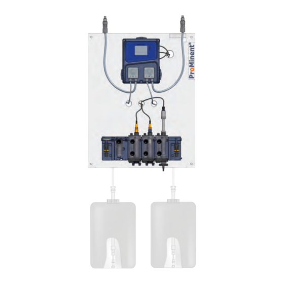
About this product About this product DULCODOS Pool metering systems are specifically designed for the treatment of swimming pool water. Pre-assembled and fully- wired ready for use, the metering systems take on the job of pH value adjustment and disinfection with chlorine. A3682 Fig. -
Page 6: Overview Of Equipment
About this product 1.1 Overview of equipment Components A3683 Fig. 2: Overview of equipment of the metering system Basic, with metering pumps Injection valve, disinfection 11. Flow module with flow sensor Controller 12. Sample valve Injection valve, acid 13. pH sensor* Metering pump, acid 14. -
Page 7: Control Elements
About this product 1.1.1 Control elements A3684 Fig. 3: Control elements for the metering system Basic The following are used as control elements: The touch display of the controller Ball valve, bypass fitting, inlet side 11. Flow meter, by scale. 12. -
Page 8: Identity Code
Identity code Identity code DSPb DULCODOS Pool Basic Regional version Europe USA USA Version PM ProMinent with BAMa Controller configuration B1 Basic pH/ORP Measured variable 1 no measured variable pH Measured variable pH, without sensor PHES 112 SE, 150702 Measured variable 2... - Page 9 Identity code DSPb DULCODOS Pool Basic German English Refer to the Product Catalogue for further languages. Approval with CE approval CE + UKCA * calculated for 12% sodium hypochlorite HB = Indoor swimming pool FB = Outdoor swimming pool...
-
Page 10: Safety And Responsibility
Safety and responsibility Safety and responsibility 3.1 User qualification WARNING! Danger of injury with inadequately qualified per‐ sonnel The operator of the system / equipment is respon‐ sible for ensuring that the qualifications are ful‐ filled. If inadequately qualified personnel work on the unit or loiter in the hazard zone of the unit, this could result in dangers that could cause serious injuries and material damage. -
Page 11: Labelling Of Warning Information
Safety and responsibility 3.2 Labelling of Warning Information Introduction These operating instructions provide information on the technical data and functions of the product. These operating instructions pro‐ vide detailed warning information and are provided as clear step- by-step instructions. The warning information and notes are categorised according to the following scheme. -
Page 12: General Safety Information
Safety and responsibility Type of information Hints on use and additional information. Source of the information. Additional measures. Denotes hints on use and other useful informa‐ – tion. It does not indicate a hazardous or dam‐ aging situation. 3.3 General safety information WARNING! Danger from hazardous substances! Possible consequence: Fatal or very serious inju‐... -
Page 13: Intended Use
Safety and responsibility Warning of feed chemical spraying around. Spraying feed chemical caused by a leak. Regularly check the system for leaks. Ensure that the system with all components can be de-ener‐ gised from outside the danger zone by appropriate measures (e.g. -
Page 14: Storage And Transport
Storage and transport Storage and transport Ambient conditions for storage and User qualification, storage and transport: instructed personnel, transport without sensors Ä Chapter 3.1 ‘User qualification’ on page 10 Basic rules. Prior to storage or transport, make sure that the metering sys‐ tems are free from feed chemicals and water. -
Page 15: Assembly
Assembly Assembly User qualification, mechanical and hydraulic installation: Ä Chapter 3.1 ‘User qualification’ trained qualified personnel on page 10 User qualification, electrical installation: electrical technician Ä Chapter 3.1 ‘User qualification’ on page 10 5.1 Scope of delivery The scope of delivery depends on the configuration of the metering system selected Tab. -
Page 16: Construction Of The Bypass Fitting
Assembly 10 mm A0924 Fig. 4: Hanger bolt; the centring of both nuts levels the distance of the plate from the wall. Rawlplug (version depending on the substrate and in line with the rawlplug manufacturer's instructions) Hanger bolt Hexagonal nut Washer Washer Hexagonal nut... - Page 17 Assembly A3236 Fig. 5: A complete bypass fitting typically consists of: Earthing connector G 1/4 connector for venting Hydraulic inlet with shut-off valve, horizontal or Hydraulic outlet with shut-off valve, horizontal or vertical connector (inlet), factory-fitted as vertical, vertical connector (outlet), factory-fitted as ver‐ but may be converted by the operator to hori‐...
-
Page 18: Hydraulic Installation
Assembly 5.4 Hydraulic installation A3685 Fig. 6: Hydraulic connection of the swimming pool metering system to the swimming pool installation Advantage: Water sampling in accordance with DIN 19643 with free drainage of the sample water. Disadvantage: Additional sample water pump and extraction point needed. Assemble the 1/2”... - Page 19 Fig. 7 on the suction and pressure side of the cir‐ culating pump Tab. 3: Interfaces, hydraulic Description Hose connection Recommended hose from the ProMinent range Sample water inlet / outlet 12x6 mm Suction line, soft PVC, 12x6...
-
Page 20: Metering System
Assembly 5.4.1 Metering system Maximum permissible operating pressure of the bypass fitting. Limit the pressure directly at the sample water extraction point to a maximum of 2 bar (at 30 °C) using a pressure reducer. Otherwise the maximum permissible operating pressure of the bypass fitting will be exceeded. -
Page 21: Testing The Hydraulic Installation Of The Metering System
Assembly 5.4.2 Testing the hydraulic installation of the metering system INFORMATION: The sample water must be free of air bubbles to ensure reliable measurement and control. Use the outlet-side shut-off valve to set a flow of 20 ... 60 l/h. Read off at the top edge of the float. -
Page 22: Installation Of The Sensors To Determine The Water Quality
All pH sensors, ORP sensors, temperature sensors Pt100 and Pt1000 as well as conductivity sensors LF(T), all with a PG 13.5 thread, Sensor adapter G 1" All ProMinent amperometric sensors, oxygen sensor DO3, conductivity sensor CCT Sensor adapter G 1" with adapter G1-3/4 Conductivity sensor... -
Page 23: Electrical Installation
Assembly 5.4.5.1 Assembly of the sensor adapter on the sensor (example shows G1” sensor adapter) Guide the O-ring (3) from below over the sensor shaft as far as the clamp disc (2). Retrofit kit "Measuring module BAMa", order no. 1113795. Guide the sensor adapter (5) from below over the sensor shaft (4) as far as the clamp disc (2). -
Page 24: Cable Cross-Sections And Cable End Sleeves
Assembly 5.5.1 Cable Cross-Sections and Cable End Sleeves Minimum cross-section Maximum cross-section Stripped insulation length Without cable end sleeve 0.25 mm 1.5 mm Cable end sleeve without 8 - 9 mm 0.20 mm 1.0 mm insulation Cable end sleeve with 10 - 11 mm 0.20 mm 1.0 mm... -
Page 25: Connecting Sensors
Assembly WARNING! Safe operating status Take safety precautions on the hardware and soft‐ ware side to ensure that the unit is in a safe oper‐ ating status in the event of a fault, for example use a limit switch, a mechanical lock etc. During installation, ensure that the unit is not ener‐... - Page 26 Assembly SPDT3: The SPDT3 input is assigned to the base valve or the suc‐ tion lance of the ORP tank. SPDT1 SPDT2 SPDT3 A2804 Fig. 13: Potential-free switch connector (remote control) De-energise the unit. Remove the front cover Strip the cable to obtain 7 mm blank cable wires and pref‐ erably remove as little as possible of the cable sleeve.
-
Page 27: Powered Relay Connector
Assembly 5.8 Powered relay connector N PE A2805 Fig. 15: Powered relay connector Use a cable with at least 1.5 mm per cable wire. De-energise the unit. Remove the front cover Strip the cable to obtain 7 mm blank cable wires and pref‐ erably remove as little as possible of the cable sleeve. -
Page 28: Terminal Diagram
Assembly 5.9 Terminal diagram Terminal identifier: Input: Note: RS 485 Mass Modbus RTU, RS 485 SPDT 1 (+) and SW* Remote control input Active (NC), normally closed, bridge, connected on delivery Pause control SPDT 2 (+) and SW* Level switch, pH correc‐ Active (NC), normally closed, bridge, connected tion (pH) -
Page 29: Cable Cross-Sections And Cable End Sleeves
Assembly 5.10 Cable Cross-Sections and Cable End Sleeves Minimum cross-section Maximum cross-section Stripped insulation length Without cable end sleeve 0.25 mm 1.5 mm Cable end sleeve without 8 - 9 mm 0.20 mm 1.0 mm insulation Cable end sleeve with 10 - 11 mm 0.20 mm 1.0 mm... -
Page 30: Assembly Of The Potential Equalisation
Assembly 5.12.2 Assembly of the potential equalisation Assembly of the potential equalisation The potential equalisation is assembled on the sensor module for pH, ORP and fluoride sensors. Unscrew the blanking plug from the bottom of the sensor module. A3259 Fig. 18: Potential equalisation plug (1) and metal pin (2) Screw the potential equalisation plug (1) in the position of the blanking plug. -
Page 31: Start Up
Start up Start up User qualification, start up: trained and qualified personnel Ä Chapter 3.1 ‘User qualification’ on page 10 Preparation: WARNING! Danger from hazardous substances! Possible consequence: Fatal or very serious inju‐ ries. Please ensure when handling hazardous sub‐ stances that you have read the latest safety data sheets provided by the manufacture of the haz‐... -
Page 32: Adjusting The Setpoint For Ph
Start up 6.1 Adjusting the setpoint for pH You need to adjust the pH in the swimming pool water to a setpoint of pH 7.2 during commissioning, as the pH of the water can be between 6.5 and 7.8 depending on the treatment method and water quality. -
Page 33: Replacing The Chemical Storage Tanks
Replacing the chemical storage tanks Replacing the chemical storage tanks WARNING! Danger from hazardous substances! Possible consequence: Fatal or very serious inju‐ ries. Please ensure when handling hazardous sub‐ stances that you have read the latest safety data sheets provided by the manufacture of the haz‐ ardous substance. -
Page 34: Operation And User Interface
Operation and user interface Operation and user interface User interface Ä Chapter 3.1 ‘User User qualification: instructed personnel qualification’ on page 10 A2807 Fig. 19: Main menu user interface. 1. Header 2. Area for pH / measuring channel 1 3. Area for ORP / measuring channel 2 8.1 Settings in the header 27,9 °C A2808... -
Page 35: Setting The Date And Time
Operation and user interface 8.1.1 Setting the date and time Time to be changed Date to be changed 24-hour format US date format A2813 Fig. 21: Date and time field Date to be changed US date format 24-hour format Time to be changed Change the settings by pressing the date and time field. - Page 36 Operation and user interface ---- 7.20 A2811 Fig. 23: Displaying the details of a measuring channel This symbol indicates the direction of the control This symbol indicates whether the over-metering (raise or lower) of the measuring channel. alarm is active. This symbol indicates the percentage metering This symbol indicates whether the sensor is cali‐...
-
Page 37: Measuring Channel Settings
Operation and user interface 8.3 Measuring channel settings Select the required measuring channel from the main screen to show this display. This configuration of the measuring channel takes effect when you close the screen and press the input and confirmation field. The parameters are not saved if the measuring channel configuration screen closes when the waiting time is exceeded. -
Page 38: Digit Input Screen
Operation and user interface 8.4 Digit input screen A2816 Fig. 26: Digit input screen Display of the measured value. Other function. Back key. Other function. This key lets you deactivate a value, e.g. to ENTER key. deactivate a timer. Cancel key. The “AM/PM”... -
Page 39: Interface Management
Operation and user interface 8.6 Interface management Interface Interface settings Brightness and contrast settings Display protection settings Colour settings A2817 Fig. 28: Display settings (interface) This button opens the control interface configuration screen. Press this key to show the next screen. Control interface configuration screen Brightness &... -
Page 40: System Information
Operation and user interface 8.8 System information System information System information pH pump - ORP pump Software version: Serial number: A2819 Fig. 30: System information This button opens the control’s system information screen. Press this key to show the next screen. Product type Software version Serial number... -
Page 41: Ph Measuring Channel Settings
Operation and user interface Temp. Timer General Communication more A2821 Fig. 32: The tabs available are: pH measuring channel settings: measuring Advanced controller settings: language, factory mode, tank level etc. settings etc. ORP measuring channel settings: measuring Communication control settings: speed, parity mode, tank level etc. - Page 42 Operation and user interface pH measuring channel in downstream mode Proportional Hysteresis value value A2823 Fig. 34: pH measuring channel in downstream mode Proportional value, e.g. 0.20 pH III Setpoint Hysteresis value, e.g. 0.20 pH IV Pump command Measuring V Hysteresis Proportional band If the feeder assembly of the pH measuring channel is configured in downstream mode, then this key is used to select the value of...
- Page 43 Operation and user interface pH measuring channel in upstream mode Hysteresis Proportional value value A2824 Fig. 35: pH measuring channel in upstream mode Proportional value, e. g. 0.20 pH III Setpoint Hysteresis value, e.g. 0.20 pH IV Pump command Measuring V Hysteresis Proportional band If the feeder assembly of the pH measuring channel is configured...
-
Page 44: Orp Measuring Channel Settings
Operation and user interface Maximum Run-in period metering time Storage tank level input Storage tank level input Active NO Inactive Max. setpoint Min. setpoint Calibration Storage tank level input limit value limit value Active NC A2825 Fig. 36: pH measuring channel settings Function This key is used to input a maximum period of use of the pump assigned to the pH sensor. - Page 45 Operation and user interface This key (1) is used to select the ORP measuring channel control mode (proportional or hysteresis mode): Proportional mode is a linear calculation, with the drive control based on a single component, the proportional mode. Hysteresis mode is a two-point control, with the hysteresis value being the gap between the setpoint and the measured value.
- Page 46 Operation and user interface ORP measuring channel in upstream mode Hysteresis Proportional value value A2824 Fig. 39: ORP measuring channel in upstream mode Proportional value, e.g. 50 mV III Setpoint Hysteresis value, e.g. 50 mV IV Pump command Measuring V Hysteresis Proportional band If the feeder assembly of the ORP measuring channel is configured in upstream mode, then this key is used to select the value of the...
- Page 47 Operation and user interface Function This key is used to input a maximum period of use of the pump assigned to the ORP sensor. This maximum time can be configured between 0 (disable or OFF) and 1440 minutes. If the period of use of the pump exceeds this time, then metering stops and is only restarted after the user has intervened.
-
Page 48: Temperature Measuring Channel Settings
Operation and user interface 8.10 Temperature measuring channel settings This screen is used to input the parameters for the temperature measuring channel. Temperature channel settings Sensor Display Displayed Run-in period fitted? value? unit Calibration Temp. A2827 Fig. 41: Temperature measuring channel settings Sensor Sensor Display... -
Page 49: Timer Settings
Operation and user interface 8.11 Timer settings This screen is used to define the operating slots of the relay. If a slot is running, then a clock symbol ½ appears in the notification bar. You can program up to 8 different daily slots for each day of the week (Monday to Sunday) or up to 8 weekly slots (All). -
Page 50: General Settings
Operation and user interface 8.12 General settings The parameters of the remote control contact, flow meter contact, feeder assembly for the pH and ORP channels and pump cycle time for the pH and ORP channels can be set on this screen. The remote control and flow switch inputs are designed so that a free potential can be connected. -
Page 51: Communication Settings
Operation and user interface Functions [Delay] input. The delay can be deactivated when the delay is set to This key is used to set the contact [OFF] . The delay can be set to up to 240 seconds. [Metering direction] of the measuring channel. The metering direction can This key is used to set the either be “upwards”... -
Page 52: Advanced Settings
Operation and user interface 8.14 Advanced settings This screen lets you adapt advanced unit settings. Factory setting: The device automatically restarts after a reset. The calibrated values are deleted so all your sensors need to be recali‐ brated. Advanced settings Metering alarm Save overmetering Activate... - Page 53 Operation and user interface Function This key activates the command in the internally fed relay, with a timer or alarm. This key restores all unit parameters to factory settings.
-
Page 54: Calibrating The Measuring Channels
Calibrating the measuring channels Calibrating the measuring channels Ä Chapter 3.1 ‘User qualifica‐ User qualification: trained user tion’ on page 10 The automatic calibration of pH or ORP does not use a standard buffer. Measure the pH with reference units or chemical reagents prior to calibration. -
Page 55: Operation And Calibration
Calibrating the measuring channels Rinse the sensor with clean water and without excessive pressure. Remove all dirt. Make sure that the sensitive tip of the sensor is not damaged. pH 7 calibration To calibrate the pH value, it is essential that you start with the liquid standard pH value of 7.00. - Page 56 Calibrating the measuring channels Calibrate the units, as described in the operating instructions for the measuring / control unit and/or the respective sensor. Close the shut-off valve on the inlet side when calibrating with standard solutions, e.g. with pH/ORP/fluoride sensors. A3206 Fig.
- Page 57 Calibrating the measuring channels Open the shut-off valve on the inlet side and correctly adjust the flow rate on the ball valve at the outlet side. Suspend the calibration beaker (4) on the collector (3) pro‐ vided for this purpose. You can take a sample at the sample valve (5) to calibrate meas‐...
-
Page 58: Operational Pause (E.g. Over-Wintering)
Operational pause (e.g. over-wintering) Operational pause (e.g. over-wintering) Never allow the sensors to remain dry in their fitting during opera‐ tional pauses. Sensors need to be stored in a dry place and pro‐ tected from moisture in their original packaging. You can obtain preservative for the sensors from your dealer. -
Page 59: Troubleshooting, Maintenance And Repair Of The Bypass Fit- Ting
Troubleshooting, maintenance and repair of the bypass fitting Troubleshooting, maintenance and repair of the bypass fit‐ ting 11.1 Diagnostics and troubleshooting User qualification, troubleshooting and fault rectification: trained user Ä Chapter 3.1 ‘User qualification’ on page 10 Error: Cause: Remedy: The float does not indi‐... -
Page 60: Maintenance Intervals
Troubleshooting, maintenance and repair of the bypass fitting WARNING! Danger from hazardous substances! Possible consequence: Fatal or very serious inju‐ ries. Please ensure when handling hazardous sub‐ stances that you have read the latest safety data sheets provided by the manufacture of the haz‐ ardous substance. -
Page 61: Cleaning Dismantled Sensor Modules
Troubleshooting, maintenance and repair of the bypass fitting 11.2.2 Cleaning dismantled sensor modules INFORMATION!: To minimise disruption to operation, you can remove individual sensor modules from the bypass fitting and replace them with cleaned sensor modules or with the hydraulic short circuit module. -
Page 62: Replacing Or Retrofitting Sensor Modules
Troubleshooting, maintenance and repair of the bypass fitting 11.2.3 Replacing or retrofitting sensor modules The bypass fitting can be extended. Appropriate retrofitting kits can Ä Chapter 11.3.1 ‘Ret‐ be ordered and integrated into the fitting. rofit kits’ on page 64 Close the shut-off valve in the feed of the bypass fitting. - Page 63 Troubleshooting, maintenance and repair of the bypass fitting A3237 Fig. 53: Fixing bolts (1) and retaining lugs (2) and (3) On the back of the bypass fitting, remove the fixing bolts (1) of the module holder that is to be removed or where the expansion module is to be fitted.
-
Page 64: Retrofit Kits, Spare Parts And Accessories
Troubleshooting, maintenance and repair of the bypass fitting 11.3 Retrofit kits, spare parts and accessories 11.3.1 Retrofit kits Tab. 5: Retrofit kits Designation includes Order no. Sensor module Sensor module, complete 1113795 Module holder All sensor adapters Knurled head screws Small components box BAMa, 1117136 Filter module Module holder... -
Page 65: Spare Parts
Troubleshooting, maintenance and repair of the bypass fitting 11.3.2 Spare parts Designation Contents Order no. Sensor module, kit Sensor module, complete 1113796 All sensor adapters: G3/4 PG 13.5 Adapter G1-3/4 NPT. 2 knurled head screws. Flow module, kit, Pool Flow module, complete 1113797 1 sensor adapter PG 13.5 2 knurled head screws... - Page 66 Troubleshooting, maintenance and repair of the bypass fitting Designation Contents Order no. Hydraulic outlet, PVC, complete Hydraulic outlet with logo 1124291 Laboratory ball valve Ø10 DN6 1/4” PVC, complete Blanking plug G1/4 with O-ring 2 PT screws Small components box BAMa, 1117136 Hydraulic inlet, PVDF, complete Hydraulic inlet 1124292...
- Page 67 Troubleshooting, maintenance and repair of the bypass fitting Designation Contents Order no. Mounting kit, G1, sensor, 25 mm Threaded sleeve G1” 1113807 O-ring, 2.00 x 3.00 Mounting kit, G1, sensor DO3, Threaded sleeve G1” short with O-ring 25.00 - 3.00 1117395 Hose connector, kit, 12x6, PCB 2 hose sleeves,12 x 6, P...
- Page 68 Troubleshooting, maintenance and repair of the bypass fitting Designation Contents Order no. Drain nozzle, kit, PG13.5, PVDF Drain nozzle, PG13.5, PVDF 1007665 Adapter M30/PG13.5 Mounting material 4 screws 1113794 4 universal rawlplugs 4 washers 12 PE plugs Mounting material, mounting kit, 1 threaded sleeve G1 1 1117395 G1, sensor DO3...
-
Page 69: Accessories
Troubleshooting, maintenance and repair of the bypass fitting 11.3.3 Accessories Tab. 6: Accessories Designation Order no. Hose connector set, 8x5, PVDF 1075939 Thermal flow control (SA 4300) 1116684 Connection cable with socket 1116687 Cutting ring threaded connector 1116686 Sensor for flow meter float (reed switch) 791635... -
Page 70: Maintenance And Faults Of The Metering System
Maintenance and faults of the metering system Maintenance and faults of the metering system User qualification, maintenance and faults: trained and quali‐ Ä Chapter 3.1 ‘User qualification’ on page 10 fied personnel WARNING! Danger from hazardous substances! Possible consequence: Fatal or very serious inju‐ ries. -
Page 71: Maintenance Interval: Weekly
Maintenance and faults of the metering system 12.1.3 Maintenance interval: weekly Regularly conduct a visual inspection of the metering system, specifically the sensors and the flow meter with flow sensor for: Air bubbles in the sample water, The condition of the sensors, Leakages, Correct flow value, To ascertain whether the flow sensor is fastened correctly... - Page 72 Maintenance and faults of the metering system WARNING! Danger from hazardous substances! Possible consequence: Fatal or very serious inju‐ ries. Please ensure when handling hazardous sub‐ stances that you have read the latest safety data sheets provided by the manufacture of the haz‐ ardous substance.
- Page 73 Maintenance and faults of the metering system A2801 Fig. 54: Changing the fuses Parameter Specification(s) Markings(s) Electrical fuse Glass fuse, 5x20 , slow-acting, 3.15 A Glass fuse, 5x20 , slow-acting, 250 mA 12.1.5.2 Maintenance of the sensors pH and ORP sensors are maintenance-free and need to be replaced when they are no longer operating perfectly.
- Page 74 Maintenance and faults of the metering system This can lead to a reduction in pump capacity over time depending on the operating conditions. There‐ fore replace the pump hose earlier if necessary. The power end is maintenance-free. 12.1.5.4 Maintenance of the system prior to the start of the season Ä...
-
Page 75: Rectifying Functional Faults
Decontaminate the device before returning it for repair. To do so, remove all traces of hazardous substances. Refer to the Material Safety Data Sheet for your feed chemical. A current Declaration of Decontamination is available to download on the ProMinent website. - Page 76 Maintenance and faults of the metering system Sign indicating EU collection system In accordance with the European Directive 2012/19/EU on waste electrical and electronic equipment, this device features the symbol showing a waste bin with a line through it. The device must not be disposed of along with domestic waste.
-
Page 77: Spare Parts: Controller And Pump
Spare parts: Controller and pump Spare parts: Controller and pump Tab. 7: Spare parts for the controller Component Order number 1009480 Pump hose, PHARMED ® Transparent cover, DF2a 1007736 Roller bearing in a transparent cover 1017985 Rotor 1009478 Union nut 1009968 Adapter G1/4 - M20x1.5 1044908... -
Page 78: Technical Data
Technical data Technical data Main features Parameter Specification(s) Markings(s) Consumption 850 W max - 3.5 A max. Power supply requirements 230 V AC +/-10%, 50 Hz Overvoltage category Electrical fuse Glass fuse, 5x20 , slow-acting, 250 mA Glass fuse, 5x20 , slow-acting, 3.15 A Operating temperature (°C) 1 °C ... - Page 79 Technical data Main features Parameter Specification(s) Markings(s) Measuring inputs 1x potentiometric (pH) 0 ... 14 pH. 1x potentiometric (ORP) 0 ... +1000 mV. 1x RTD (4..20 mA) -5 ... 45 °C. TEMP Control or flow inputs 1x remote input in “On/Off Control” SPDT1 Control 1x flow switch detection SPDT4...
-
Page 80: Index
Index Index 1, 2, 3 ... 4 designs of sensor adapter ....22 Non-discriminatory approach ....2 Accessories . - Page 81 Index Spare parts for accessories ....77 Storage ....... . 14 Transport .
- Page 84 ProMinent GmbH Im Schuhmachergewann 5 - 11 69123 Heidelberg, Germany Telephone: +49 6221 842-0 Fax: +49 6221 842-419 Email: info@prominent.com Internet: www.prominent.com 990231, 1, en_GB © 2023...
Need help?
Do you have a question about the DULCODOS DSPb and is the answer not in the manual?
Questions and answers