Table of Contents
Advertisement
Quick Links
Assembly and operating instructions
DULCODOS Pool Basic
EN
A0953
Please carefully read these operating instructions before use. · Do not discard.
The operator shall be liable for any damage caused by installation or operating errors.
The latest version of the operating instructions are available on our homepage.
Part no. 984277
Original Operating Instructions (2006/42/EC)
Version: BA DD 032 03/15 EN
Advertisement
Table of Contents

Related Manuals for ProMinent DULCODOS Pool Basic


Summary of Contents for ProMinent DULCODOS Pool Basic
- Page 1 Assembly and operating instructions DULCODOS Pool Basic A0953 Please carefully read these operating instructions before use. · Do not discard. The operator shall be liable for any damage caused by installation or operating errors. The latest version of the operating instructions are available on our homepage.
- Page 2 Supplemental directives General non-discriminatory approach In order to make it easier to read, this document uses the male form in grammatical structures but with an implied neutral sense. It is aimed equally at both men and women. We kindly ask female readers for their understanding in this simplification of the text.
-
Page 3: Table Of Contents
Table of contents Table of contents Identity code................4 About this product..............6 2.1 Overview of Equipment..........6 Safety and Responsibility............8 3.1 Users' qualifications............8 3.2 Explanation of the safety information......9 3.3 General Safety Information......... 10 3.4 Intended Use.............. 12 Storage and transport............ -
Page 4: Identity Code
Communication interfaces: none Electrical connection: 230 V, 50/60 Hz, European standard plug 230 V, 50/60 Hz, Swiss plug Sensor equipment: with sensors without sensors Design: with ProMinent logo without ProMinent logo Language: German Italian English Dutch French Russian Czech... - Page 5 Identity code DSPa DULCODOS Pool Basic ® DULCO ® flex (peristaltic pump): 0.8 l/h for up to 45/10 m /h circulation HB/FB* 1.6 l/h for up to 90/20 m /h circulation HB/FB* 2.4 l/h for up to 140/30 m /h circulation HB/FB* alpha (motor-driven metering pump): 1.8 l/h for up to 100/20 m...
-
Page 6: About This Product
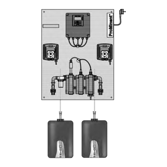
About this product About this product DULCODOS Pool metering systems are specifically designed for ® the treatment of swimming pool water. Ready mounted, fully-wired and ready for use, they take on the job of pH value adjustment and disinfection with chlorine. DULCODOS ®... - Page 7 About this product Control elements A0955 Fig. 2: Control elements of the DULCODOS ® Pool metering system Basic (with all options and metering pumps alpha) The following are used as control elements: Controller keys and display concealed, stroke adjustment dial inside the metering pump concealed, stroke adjustment dial inside the metering pump Ball valve, in-line probe housing, inlet side 11.
-
Page 8: Safety And Responsibility
Customer Service depart‐ Customer Service department refers to service technicians, who have ment received proven training and have been authorised by ProMinent to work on the system. Note for the system operator The pertinent accident prevention regulations, as... -
Page 9: Explanation Of The Safety Information
Safety and Responsibility 3.2 Explanation of the safety information Introduction These operating instructions provide information on the technical data and functions of the product. These operating instructions pro‐ vide detailed safety information and are provided as clear step-by- step instructions. The safety information and notes are categorised according to the following scheme. -
Page 10: General Safety Information
Safety and Responsibility Type of information Hints on use and additional information Source of the information, additional measures Information! Denotes hints on use and other useful informa‐ – tion. It does not indicate a hazardous or dam‐ aging situation. 3.3 General Safety Information WARNING! Danger from hazardous substances! Possible consequence: Fatal or very serious inju‐... - Page 11 Safety and Responsibility WARNING! Operating faults! Possible consequence: Fatal or very serious inju‐ ries. – Ensure that the unit is only operated by ade‐ quately qualified and technically expert per‐ sonnel – Please also observe the operating instructions for controllers and fittings and any other com‐ ponent groups, such as sensors, sample water pumps ...
-
Page 12: Intended Use
Safety and Responsibility NOTICE! Correct sensor operation Damage to the product or its surroundings. – Correct measuring and metering is only pos‐ sible if the sensor is working perfectly – Check and calibrate the sensor regularly NOTICE! Compensation for control deviations Damage to the product or its surroundings –... -
Page 13: Storage And Transport
Storage and transport Storage and transport Ambient conditions for storage and transport without sensors CAUTION! – Prior to storage or transport, the DULCODOS ® Pool metering systems must be free from feed chemicals and water – Rinse out the media carrying parts, including the tubes using clean, pure water –... -
Page 14: Assembly
Assembly Assembly 5.1 Wall mounting Secure the metering system perpendicular and upright on a wall or a stable mounting system. The metering system should be freely accessible. Select the mounting height you require so that: The controller's display can be easily read There is still space for maintenance work beneath the in-line probe housing (100 mm) There is still room for the chemical storage tank (600 mm) -
Page 15: Hydraulic Installation
Assembly 5.2 Hydraulic installation A0957 Fig. 4: Hydraulic connection of the swimming pool metering system to the swimming pool installation Advantage: Water sampling in accordance with DIN 19643 with free drainage of the sample water Disadvantage: Additional sample water pump and sample water extraction point needed. - Page 16 Disadvantage: The measured value is possibly falsified by depletion in the surge water tank is and then not representative of the water in the swimming pool. Tab. 2: Interfaces, Hydraulic Description Hose connection Recommended hose from the ProMinent range Sample water inlet / outlet 8 x 5 mm Suction line, soft PVC, 8 x 5...
-
Page 17: Metering System
Assembly 5.2.1 Metering system NOTICE! Maximum permissible operating pressure of in-line probe housing Limit the pressure to a maximum of 2 bar (at 30 °C) directly at the sample water extraction point using a pressure reducer, otherwise the maximum permissible operating pressure of the in-line probe housing will be exceeded. -
Page 18: Sensors
Assembly Testing the hydraulic installation of the metering system: To ensure reliable measuring and control, the sample water must be free from air bubbles. Set a flow of 20 ... 60 l/h using the stopcock (read-off at the top edge of the float). Check the hydraulic leak-tightness of the system (escaping liquid, continuous air bubbles in the in-line probe housing, ...) ð... -
Page 19: Electrical Installation
Assembly 5.3 Electrical installation Screw the orange-coloured SN6 plugs onto the sensors Plug the mains plug for the metering system into a socket 5.3.1 Install external signal inputs and signal outputs Terminal Description Technical Data XK1:1-2 Sample water monitoring* Open circuit voltage: 15 V Short circuit current: 1.8 mA XK1:3-4 Pause input*... -
Page 20: Start Up
Start up Start up Preparation: WARNING! Danger from hazardous substances! Possible consequence: Fatal or very serious inju‐ ries. Please ensure when handling hazardous sub‐ stances that you have read the latest safety data sheets provided by the manufacture of the haz‐ ardous substance. -
Page 21: Setting The Setpoint For Ph
Start up Maximum permissible operating pressure: In the sample water line: 2 bar at 30 °C (sample water) Tighten all threaded connectors prior to initial commissioning Open the shut-off valves downstream of the metering pumps, in the sample water line and also the shut-off valves in your system Insert the suction lances into the relevant chemical storage tanks for acid or disinfectant (e.g. -
Page 22: Adjust The Flow Sensor Switching Point
Start up 6.3 Adjust the flow sensor switching point The flow sensor should switch when the flow falls (flow sensor is con‐ Sample water may escape. nected as an NC). Adjust the flow to 50 l/h using the ball valve Hold the flow sensor in place and loosen the mounting clip a little Press the float to 40 l/h using the flow sensor... -
Page 23: Operating And Replacing The Storage Tank
Operating and replacing the storage tank Operating and replacing the storage tank Ä Chapter 3.1 User qualification: Instructed person, see ‘Users' qualifications’ on page 8 7.1 Replacing the chemical storage tanks WARNING! Danger from hazardous substances! Possible consequence: Fatal or very serious inju‐ ries. -
Page 24: Operating Elements
Operating and replacing the storage tank 7.2 Operating elements A1824 Fig. 8: Operating elements 1. LCD display 5. "Down" key [CAL/ESC] key [Start/Stop] key [OK] key [Menu] key 4. "Up" key... -
Page 25: Operating Structure
Operating and replacing the storage tank Tab. 3: The controller's graphic display uses the following symbols: Symbol Meaning [Start/Stop] key pressed Error pH setpoint exceeded 2-point controller 1 Acid metered pH setpoint undershot 2-point controller 1 Alkali metered ORP setpoint exceeded 2-point controller 2 Oxidant, top ORP setpoint undershot... - Page 26 Operating and replacing the storage tank Continuous Continuous display 1a display 1 Continuous Continuous display 2 display 2a Menu point 2 Menu point 1 Setting menu 1 Menu point 1 Setting menu X A1806 Fig. 9: Operating menu, diagrammatical The operating menu comprises the continuous displays the setting menus the menu items in the setting menus...
- Page 27 Operating and replacing the storage tank Qualified personnel also have the following additional options of: Switching the relay function from pulse length to two-point con‐ trol Switching the metering delay time and the metering control time...
- Page 28 Operating and replacing the storage tank Operating Menu 6.99 value 1 6.99 pH value 2 500 mV error message 1 value 1 6.99 pH value 2 500 mV s. point 7.20 pH s. point 650 mV ctrlout 50 % ctrlout 50 % priming acid press -key...
- Page 29 Operating and replacing the storage tank The displays individually are as fol‐ Continuous display 1: lows: The pH-value is shown as a 4-digit number, with two digits after the decimal point. The unit (pH) appears on the right beside the value. The ORP value is shown as a 3-digit number.
- Page 30 Operating and replacing the storage tank Pulse length 1 and Pulse length 2 menu items [pulse length] ‘Relay 1 pH’ These two menu items appear if in the menu item [relais 1 pH] the function ‘Pulse length’ [pulse length] has been selected.
- Page 31 Operating and replacing the storage tank The processes Sample water [sample water] and Pause [pause] [activ closed] (symbol for can be individual set as active closed [activ open] (symbol for "N/C"). The time "N/O") or as active open ‘Td’ determines the time after which the control becomes active again after the Pause has been stopped.
-
Page 32: Menu Items
Operating and replacing the storage tank Errors that relate to the measured variable pH will be reset during successful calibration. Following calibration, metering, control and troubleshooting restart after elapse of the metering delay (2 min = standard setting). Menu item: Sensor in buffer? The unit awaits confirmation that the pH sensor to be calibrated is immersed in buffer 1 and/or buffer 2. - Page 33 Operating and replacing the storage tank If you do not want to save the set variables, then exit the [CAL /ESC] : menu item by pressing ð You will return to the setting menu. CHANGE from selection to selection Return without saving setting.
-
Page 34: Operating And Adjustment
Operating and replacing the storage tank 7.3.2 Operating and adjustment Monitoring 6.99 value 1 6.99 pH value 2 500 mV error message 1 value 1 6.99 pH value 2 500 mV s. point 7.20 pH s. point 650 mV ctrlout 50 % ctrlout 50 %... - Page 35 Operating and replacing the storage tank 6.99 value 1 6.99 pH value 2 500 mV error message 1 value 1 6.99 pH value 2 500 mV s. point 7.20 pH s. point 650 mV ctrlout 50 % ctrlout 50 % priming acid press -key pump off...
-
Page 36: Maintenance And Faults
Maintenance and faults Maintenance and faults Flush the metering system with a suitable flushing medium prior to maintenance - refer to the latest safety data sheets for the feed chemical. Observe the operating instructions for the metering pump, the in-line probe housing, the sensors, dirt filter and multifunctional valve (optional). -
Page 37: Check Sensors
Maintenance and faults Maintenance interval: weekly Regularly conduct a visual inspection of the metering system, specifically the sensors and the flow meter with flow sensor for: Air bubbles in the sample water The state of the sensors Leakages Correct flow values To ascertain whether the flow sensor is fastened correctly onto the flow meter To ascertain whether the float is moving easily within the... - Page 38 Maintenance and faults Unscrew the pH sensor from the in-line probe housing Screw the SN 6 plug onto the pH sensor Rinse the pH sensor with distilled water and dab it with a dry, soft cloth. Dip the pH sensor in pH 7 buffer solution and stir ð...
-
Page 39: Troubleshooting
Decontaminate the unit before returning it for repair. To do so, remove all traces of hazardous substances. Refer to the Material Safety Data Sheet for your feed chemical. A current Declaration of Decontamination is available to download on the ProMinent website. -
Page 40: Technical Data
Technical Data Technical Data Refer to the product-specific operating instructions for technical data on the controller, sensors, in-line probe housing, metering pump and multifunctional valve. Maximum permissible operating pressure In the sample water line: 2 bar at 30 °C (sample water) Sample water line connector 8 x 5 mm PE hose Sample water filter element... - Page 41 Technical Data Ø 8,5 A2091 Fig. 17: Dimensions sheet. All dimensions in mm.
- Page 42 Technical Data Ø 8,5 A2092 Fig. 18: Dimensions sheet. All dimensions in mm.
-
Page 43: Terminal Diagram
Technical Data 9.1 Terminal diagram INTERN EINGÄNGE AUSGÄNGE pH-Sensor Hardware-key Redox-Sensor Digitaler Kontakteingang 1 Durchflußüberwachung Messwasserfehler Pause Digitaler Kontakteingang 2 Niveaukontakt Digitaler Kontakteingang 3 Behälter 1 Digitaler Kontakteingang 4 Niveaukontakt Behälter 2 Alarmrelais Alarm Pumpe alpha ALPc, Dulcoflex Pumpe P1, Leistungsrelais 1 senken Impulslänge... -
Page 44: Appendices
Appendices Appendices 10.1 Spare parts and accessories The following are needed for the maintenance of a DULCODOS ® Pool: 2 no. maintenance kits for the metering pumps 1 no. maintenance kit for the measured variable Maintenance Kits for Metering Pumps Tab. -
Page 45: Ec Declaration Of Conformity
In accordance with DIRECTIVE 2006/42/EC OF THE EUROPEAN PARLIAMENT AND OF THE COUNCIL, Appendix I, BASIC HEALTH AND SAFETY REQUIREMENTS, section 1.7.4.2. C. Without pumps ProMinent Dosiertechnik GmbH Im Schuhmachergewann 5 - 11 DE - 69123 Heidelberg, hereby declare that the product specified in the following, complies... - Page 46 Appendices With pumps ProMinent Dosiertechnik GmbH Im Schuhmachergewann 5 - 11 DE - 69123 Heidelberg, hereby declare that the product specified in the following, complies with the relevant basic health and safety requirements of the EC Directive, on the basis of its functional concept and design and in the version distributed by us.
-
Page 47: Index
Index Index Question: What options are available in terms of "Maintenance and faults"? ....36 Access code ......33 Question: What should I consider when Action, step by step . - Page 48 ProMinent GmbH Im Schuhmachergewann 5 - 11 69123 Heidelberg Telephone: +49 6221 842-0 Fax: +49 6221 842-419 Email: info@prominent.com Internet: www.prominent.com 984277, 2, en_GB © 2015...
Need help?
Do you have a question about the DULCODOS Pool Basic and is the answer not in the manual?
Questions and answers