Table of Contents
Advertisement
Quick Links
Assembly and operating instructions
DULCODOS Pool Soft
EN
A1746
Please carefully read these operating instructions before use. · Do not discard.
The operator shall be liable for any damage caused by installation or operating errors.
The latest version of the operating instructions are available on our homepage.
Part number 984127
Original Operating Instructions (2006/42/EC)
Version: BA DD 034 06/15 EN
Advertisement
Table of Contents

Related Manuals for ProMinent DULCODOS Pool Soft


Summary of Contents for ProMinent DULCODOS Pool Soft
- Page 1 Assembly and operating instructions DULCODOS Pool Soft A1746 Please carefully read these operating instructions before use. · Do not discard. The operator shall be liable for any damage caused by installation or operating errors. The latest version of the operating instructions are available on our homepage.
- Page 2 Supplemental directives General non-discriminatory approach In order to make it easier to read, this document uses the male form in grammatical structures but with an implied neutral sense. It is aimed equally at both men and women. We kindly ask female readers for their understanding in this simplification of the text.
-
Page 3: Table Of Contents
Table of contents Table of contents Identity code................5 About This Product............... 7 2.1 Overview of Equipment..........7 Safety and Responsibility............9 3.1 Users' qualifications............9 3.2 Explanation of the safety information......10 3.3 General Safety Information......... 11 3.4 Intended Use.............. 13 Operating Concept.............. - Page 4 Table of contents EC Declaration of Conformity..........64 Index................... 66...
-
Page 5: Identity Code
Identity code Identity code DSPa DULCODOS ® Pool Measured variable: DO2 pH/Timer control H (DACa) Auxiliary hardware functions: Screen plotter with measured data backup including SD card Auxiliary software functions: Screen plotter with measured data backup including SD card Communication interfaces: none Embedded web server, LAN Electrical connection:... - Page 6 Identity code DSPa DULCODOS Pool ® 1.6 l/h (DULCO ® flex DF2a 0216) 2.4 l/h (DULCO ® flex DF2a 0224) 1.8 l/h (alpha ALPc 1002 PVT) 3.5 l/h (alpha ALPc 1004 PVT) 1.5 l/h (Beta ® BT4b 0401 PVT) 2.8 l/h (Beta ®...
-
Page 7: About This Product
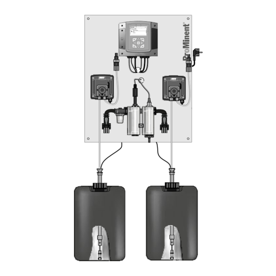
About This Product About This Product DULCODOS Pool metering systems are specifically designed for ® the treatment of swimming pool water. Ready mounted and fully- wired, DULCODOS Pool metering systems provide pH adjust‐ ® ment and disinfection using H DULCODOS Pool metering systems are equipped with all the ®... - Page 8 About This Product Soft control elements A1748 Fig. 2: Control elements for the DULCODOS ® Pool Soft (with all options and Beta metering pumps) ® The following are used as control elements: Controller keys and display Flow meter (by scale) Stroke adjustment dial on the metering pump (con‐...
-
Page 9: Safety And Responsibility
Customer Service depart‐ Customer Service department refers to service technicians, who have ment received proven training and have been authorised by ProMinent to work on the system. Note for the system operator The pertinent accident prevention regulations, as... -
Page 10: Explanation Of The Safety Information
Safety and Responsibility 3.2 Explanation of the safety information Introduction These operating instructions provide information on the technical data and functions of the product. These operating instructions pro‐ vide detailed safety information and are provided as clear step-by- step instructions. The safety information and notes are categorised according to the following scheme. -
Page 11: General Safety Information
Safety and Responsibility Type of information Hints on use and additional information Source of the information, additional measures Information! Denotes hints on use and other useful informa‐ – tion. It does not indicate a hazardous or dam‐ aging situation. 3.3 General Safety Information WARNING! Danger from hazardous substances! Possible consequence: Fatal or very serious inju‐... - Page 12 Safety and Responsibility WARNING! Operating faults! Possible consequence: Fatal or very serious inju‐ ries. – Ensure that the unit is only operated by ade‐ quately qualified and technically expert per‐ sonnel – Please also observe the operating instructions for controllers and fittings and any other com‐ ponent groups, such as sensors, sample water pumps ...
-
Page 13: Intended Use
Safety and Responsibility NOTICE! Correct sensor operation Damage to the product or its surroundings. – Correct measuring and metering is only pos‐ sible if the sensor is working perfectly – Check and calibrate the sensor regularly NOTICE! Compensation for control deviations Damage to the product or its surroundings –... -
Page 14: Operating Concept
Operating Concept Operating Concept A1035 Fig. 3: Operating cross (1) / Active keys are displayed in [black] in the display; inactive keys in [grey]. For example, the following path is presented: [calibrate] ➨ Continuous display ➨ ➨ ➨ [slope] ➨ ➨... - Page 15 Operating Concept Fig. 5: Example of the continuous display when used with a meas‐ uring channel (e.g. pH) 7.55 7.20 0.30 0.50 A1177 Fig. 6: Example of the continuous display when used with two measuring channels (e.g. pH/chlorine) Setting of the various parameters in the adjustable menus No time-controlled menu items The controller does not exit any menu items in a...
-
Page 16: Functions Of The Keys
Operating Concept You can adjust the desired value in the setting menu using the four arrow keys and then save it using the ð Range error If you enter a value that is outside the possible setting range, the message [range error] appears after pressing the key. -
Page 17: Changes The Set Operating Language
Operating Concept 4.2 Changes the set operating language Simultaneously press the keys ð The controller changes to the menu for setting the oper‐ ating language. Language Language German A1482 Fig. 7: Menu for setting the operating language Now using keys you can set the desired operating language Confirm your selection by pressing the key... -
Page 18: Key Lock
Operating Concept Fig. 8: Alarm message, controller stops control 4.4 Key Lock The controller has a key lock. If the key lock is activated, the keys cannot be pressed. The key lock can be activated or deactivated by simultaneously pressing . -
Page 19: Storage And Transport
Storage and transport Storage and transport Ambient conditions for storage and transport without sensors CAUTION! – Prior to storage or transport, the DULCODOS ® Pool metering systems must be free from feed chemicals and water – Rinse out the media carrying parts, including the tubes using clean, pure water –... -
Page 20: Assembly
Assembly Assembly 6.1 Wall-mounting Secure the metering system perpendicular and upright on a wall or a stable mounting system. The metering system should be freely accessible. Select the mounting height you require so that: All components are easily accessible The controller's display can be easily read [Park position] The controller cover can still be parked in the (150 mm) -
Page 21: Fit The Antikink Device For The Bleed Line
Assembly 6.2 Fit the antikink device for the bleed line Only SEK liquid end (metering pump Beta ® for disinfection, right side): A0965 Fig. 10: Fit the antikink device for the bleed line (only SEK liquid end) 1. Bleed valve for the return line in the storage tank, 6/4 mm 2. -
Page 22: Hydraulic Installation
Assembly 6.3 Hydraulic Installation A1751 Fig. 11: Skimmer pool: hydraulic connection of the swimming pool metering system to the swimming pool installation Advantage: Simple installation Disadvantage: In-line probe housing can become dirty... -
Page 23: Metering System
Assembly A1752 Fig. 12: Overflow pool: hydraulic connection of the swimming pool metering system to the swimming pool installation Advantage: Simple installation Disadvantage: In-line probe housing can become dirty 6.3.1 Metering system WARNING! Possible over-metering Consequence: Severe damage to health caused by the feed chemical used. - Page 24 Assembly A2083 Fig. 13: Multifunctional switch (1) set to [EXTERNAL] NOTICE! Maximum permissible operating pressure of the in- line probe housing Limit the pressure on the measured water extrac‐ tion point to a maximum of 2 bar (at 30 °C) using a pressure reducer.
- Page 25 Assembly Screw the injection valves into a straight union on the filtra‐ tion circuit pipe P_BE_0008_SW Fig. 14: Overview of liquid end (PV) beta and alpha Discharge valve Backplate Dosing head Bleed valve Bypass hose sleeve Suction valve A0929 Fig. 15: Connecting the hose using the connector kit 1.
-
Page 26: Sensors
Assembly Using the connector kit, connect the pressure hose to the pressure connector Lead the bypass line back into the dosing tank Using the connector kit, connect the pressure hose to the injection valve Testing the hydraulic installation of the metering system: The sample water should be free from air bubbles to ensure reliable measurement and control. -
Page 27: Electrical Installation
Assembly Testing the sensors' hydraulic installation: Adjust the flow using the shut-off valve to 20... 60 l/h ð Check whether the threaded connectors on the in-line probe housing are tight. 6.4 Electrical Installation The controller is used to switch and provide the power supply to the metering pumps alpha and Beta. -
Page 28: Electrical Installation Of The Sensors
Assembly Terminal Description Technical Data XR3:1-3 Alarm relay max. 250 VAC, max. 3 A, max. 700 VA contact type: changeover XP2:L,N, PE Mains connection 230 VAC ± 10 %, 50/60 Hz 6.4.3 Electrical Installation of the Sensors Electrical installation of the pH sensor Screw the orange-coloured SN6 plug onto the sensor. -
Page 29: Start Up
Start Up Start Up Preparation: WARNING! Danger from hazardous substances! Possible consequence: Fatal or very serious inju‐ ries. Please ensure when handling hazardous sub‐ stances that you have read the latest safety data sheets provided by the manufacture of the haz‐ ardous substance. -
Page 30: Priming And Bleeding (With An Alpha Or Beta Pump)
Start Up 7.1 Priming and bleeding (with an alpha or Beta pump) WARNING! Danger from hazardous substances! Possible consequence: Fatal or very serious inju‐ ries. Measure: The bleed valve must be equipped with a transparent PVC hose (6 x 4 mm). The PVC hose must be connected to the respective chemical storage tank so that the leaking chemicals can flow back into the chemical storage tank during the... -
Page 31: Calibration
Start Up Press the float to 40 l/h using the flow sensor ð The error message should disappear. Hold the flow sensor in this position and tighten the mounting clip Then re-adjust the flow required using the ball valve Acknowledge any error message that occurs Reset any possible consequences of this in the overall instal‐... -
Page 32: Calibration
Start Up Preparing the filtration circuit WARNING! Danger from hazardous substances! Possible consequence: Fatal or very serious inju‐ ries. Please ensure when handling hazardous sub‐ stances that you have read the latest safety data sheets provided by the manufacture of the haz‐ ardous substance. - Page 33 Start Up 7.3.1.1 Calibrating the pH sensor To ensure a high level of measuring accuracy, adjust the pH sensor at set time intervals. This calibration interval seriously depends on the application of the pH sensor and on the required measurement accuracy and reproducibility. The calibration interval can vary between daily and every few months.
- Page 34 Start Up Selecting the calibration process Select the calibration process prior to initial calibration. This selec‐ tion is saved until you select a new process. 2-point calibration: This is the recommended calibration process because it evaluates the sensor characteristic data: asymmetric potential, slope and response speed.
- Page 35 Start Up Buffer temperature dependencies Buffer temperature At temperatures that differ by 25 °C in the process, adjust the pH of the buffer solution by entering the reference values printed on the buffer solution bottle into the controller prior to calibration. Buffer temperature dependencies An incorrectly entered buffer temperature can lead to incorrect calibration.
- Page 36 Start Up CAL pH Buffer 1: Buffer 2: Calibr.param. for 25 °C Slope % Slope Asymmetry Zero point Accept with <CAL> A1019 Fig. 16: Display of the calibration result CAL pH Sensor quality Asymmetry in mV good acceptable good Slope in mV/pH A1481 Fig.
- Page 37 Start Up Press CAL pH Calibration process 2 point Buffer detection requirement Buffer manufacturer ProMinent Buffer value 1 pH 7 Buffer value 2 pH 4 Buffer temperature A1025 Fig. 18: Selecting the calibration process ð The menu for selecting the calibration process appears.
- Page 38 [Requirement]: you have to select 2 buffers from the 4 possible buffer sets for this. Adhere to the selected order, e.g. buffer value 1: pH 7 and buffer value 2: pH 4 for calibration. ProMinent (pH 4; 7; 9; 10) – ®...
- Page 39 Start Up CAL pH Last calibration 14:26:07 06/04/2013 Slope 56.64mV/pH Zero point 7,00 pH CAL setup Calibration process 2 point continue with <CAL> A1016 Fig. 20: pH sensor calibration (CAL) Then press Rinse the sensor thoroughly with water before drying with a cloth (pad dry, don't rub) Immerse the sensor in test container 1 containing buffer solu‐...
- Page 40 Start Up CAL pH Sensor calibration in buffer 2 Sensor voltage 173 mV Buffer temperature 25.0 °C The stability is: good acceptable very good continue with <CAL> A1018 Fig. 22: Display of the sensor stability achieved [acceptable / good / very good] range is displayed ð...
- Page 41 Start Up 7.3.1.1.3 pH sensor calibration (CAL) with an external sample (1-point) Measuring and control behaviour of the controller during calibration During calibration the actuating outputs are deacti‐ vated. Exception: a basic load or a manual control variable has been set. This remains active. The measured value output [standard signal output mA] is frozen, corresponding to its settings in the mA output menu.
- Page 42 Start Up Continuous display ➨ CAL pH Last calibration 06/05/2013 14:26:07 Zero point Slope CAL setup Sample (1-point) Calibration process Buffer temperature Manual continue with <CAL> A1023 Fig. 24: pH sensor calibration (CAL) Continue with Take a water sample at the in-line probe housing and, using a suitable method (measuring strips, hand measuring instru‐...
- Page 43 Start Up Incorrect calibration An error message appears if the result of the cali‐ bration lies outside the specified tolerance limits. In this case, the current calibration is not applied. Check the prerequisites for calibration and clear the error. Then repeat calibration. Transfer the result of the calibration into the controller memory by pressing ð...
- Page 44 Start Up CAL pH Last calibration 06/05/2013 16:47:32 Zero point 7,00 pH Slope 59.16 mV/pH CAL setup Calibration process Data input continue with <CAL> A1024 Fig. 26: pH sensor calibration (CAL) Continue with CAL pH Slope -58.07 mV/pH at 25.0 °C -6.4 mV Asymmetry at 25.0 °C...
-
Page 45: Diagnostics
[Diagnostics] [Diagnostics] Ä Chapter 3.1 ‘Users' User qualification: instructed user, see qualifications’ on page 9 [Diagnostics] ➨ Continuous display ➨ ➨ [Diagnostics] It is possible to look through log books, perform a simulation of out‐ puts or view device information in this menu. Diagnostics Logbook Simulation... -
Page 46: Reading The [Error Log Book]
[Diagnostics] The following data is stored: Name of the measuring channel Measured variable Time of calibration Zero point Slope Deleting entries in You can also delete entries in the Calibration log book. Deleting [Calibration log book] the entries does not affect the calibrations stored in the controller. [Error Log Book] 8.1.2 Reading the [Error log book] . -
Page 47: Displaying [Device Information]
[Diagnostics] [Simulation] menu item enables you to activate all outputs for test purposes during commissioning. A simulated output remains [Simulation] menu item. It is also pos‐ activated until you quite the [Simulation] sible to prime a peristaltic pump, for example, with mode. - Page 48 [Diagnostics] Error Error message text Cause Remedy Check the coaxial cable connection for corrosion and moisture and replace with a new cable, if necessary pH/ORP sensor is faulty Replace the sensor The mV input voltage The connected signal does Check the origin of the sensor signal. is too high not come from a pH sensor Check the raw signal by pressing...
- Page 49 [Diagnostics] Error Error message text Cause Remedy The mA input current The power circuit is discon‐ Check the 2-wire connection between is too low nected the sensor/transmitter and controller and check the raw value in mA by pressing . If the value is 0 mA, then the connection is disconnected After elapse of the The measured value lies...
- Page 50 [Diagnostics] Error Error message text Cause Remedy The level in the The chemical in storage tank Add the corresponding chemical storage tank 1 is too 1 is used up The level in storage The chemical in storage tank Add the corresponding chemical tank 2 is too low 2 is used up The level in storage...
- Page 51 [Diagnostics] Tab. 7: Warning alerts Warning Warning alert text Cause Remedy The limit value was The measured value is below Check whether the choice of the limit undershot the limit value value matches the application and adjust if necessary. Check the design of the actuator: has too small an actuator been selected? Check the concentration of the feed chemical: is the concentration too low?
-
Page 52: Help Texts
[Diagnostics] 8.5 Help texts Content of the help Cause Remedy texts The DPD value is too If the calculated reference value (e.g. Increase the concentration of the chem‐ small, DPD value > DPD1) for calibrating a sensor is less ical to be measured in the process/ MRS + 2 % than 2 % of the measuring range, then sample water and determine the refer‐... -
Page 53: Maintenance Work
Maintenance Work Maintenance Work Tab. 8: An overview of maintenance work Maintenance interval Maintenance task daily Check swimming pool water values weekly Visually inspect the metering system (flow meter) Only with Beta ® metering pump: metering pump LEDs Check storage tank liquid levels Check sensor 6 months Clean dirt filters... -
Page 54: Replacing The Chemical Storage Tanks
Maintenance Work Maintenance interval: 6 months Clean dirt filter regularly: Close the stopcocks upstream and downstream of the in-line probe housing Unscrew the filter bowl Remove the filter insert and clean it without detergent Insert the filter insert into the housing Check the sealing ring and the sealing surfaces for cleanli‐... -
Page 55: Troubleshooting
Decontaminate the unit before returning it for repair. To do so, remove all traces of hazardous substances. Refer to the Material Safety Data Sheet for your feed chemical. A current Declaration of Decontamination is available to download on the ProMinent website. -
Page 56: Technical Data
Technical Data Technical Data Refer to the product-specific operating instructions for technical data on the controller, sensors, in-line probe housing, metering pump and multifunctional valve. Maximum permissible operating pressure In the sample water line: – 2 bar at 30 °C (sample water) Sample water line connector 8 x 5 mm PE hose Sample water filter element... -
Page 57: Wiring Diagram
Digitaler Kontakteingang 3 Niveaukontakt Behälter 2 Digitaler Kontakteingang 4 Niveaukontakt Behälter 3 pH-Sensor Potenzialausgleich (pH) Temperatursensor (Stromquelle) Potenzialausgleich Temperatursensor ProMinent-Sensor (2 - Leiter) Pumpe P1, senken Pumpe P2, heben Messwert Messwert Pumpe P3, senken Pumpe P4, heben Pumpe P1, senken Leistungsrelais 1... - Page 58 Digitaler Kontakteingang 3 Niveaukontakt Behälter 2 Digitaler Kontakteingang 4 Niveaukontakt Behälter 3 pH-Sensor Potenzialausgleich (pH) Temperatursensor (Stromquelle) Potenzialausgleich Temperatursensor ProMinent-Sensor (2 - Leiter) Pumpe P1, heben Pumpe lmpulsfrequenzausgang 2 Pumpe P2, senken Messwert Messwert Pumpe Pumpe P3, heben lmpulsfrequenzausgang 3...
-
Page 59: Drawings, Drilling And External Dimensions Of The Dulcodos
Technical Data 10.2 Drawings, Drilling and External Dimensions of the DULCODOS ® Versions of the DULCODOS ® The drawings show three possible versions of the DULCODOS . The drilling and external dimen‐ ® sions of the DULCODOS are identical with all ver‐ ®... - Page 60 Technical Data Ø 8,5 A2162 Fig. 36: Drawing, drilling and external dimensions of the DULCODOS with metering pump Dulcoflex ® ®...
- Page 61 Technical Data Ø 8,5 A2163 Fig. 37: Drawing, drilling and external dimensions of the DULCODOS with metering pump alpha ®...
-
Page 62: Spare Parts And Accessories
Spare Parts and Accessories Spare Parts and Accessories The following are needed for the maintenance of a DULCODOS ® Pool: 2 no. maintenance kits for the metering pumps 1 no. maintenance kit for the measured variable Maintenance kits for metering pumps Tab. - Page 63 Spare Parts and Accessories Tab. 12: Accessories Accessories Order number Photometer DT3B: For determination of H 1039317...
- Page 64 In accordance with DIRECTIVE 2006/42/EC OF THE EUROPEAN PARLIAMENT AND OF THE COUNCIL, Appendix I, BASIC HEALTH AND SAFETY REQUIREMENTS, section 1.7.4.2. C. Without pumps ProMinent Dosiertechnik GmbH Im Schuhmachergewann 5 - 11 DE - 69123 Heidelberg, hereby declare that the product specified in the following, complies...
- Page 65 EC Declaration of Conformity With pumps ProMinent Dosiertechnik GmbH Im Schuhmachergewann 5 - 11 DE - 69123 Heidelberg, hereby declare that the product specified in the following, complies with the relevant basic health and safety requirements of the EC Directive, on the basis of its functional concept and design and in the version distributed by us.
- Page 66 Index Index Question: How can I set or change the operating language? ......17 Action, step by step .
- Page 67 Index Users' qualifications ..... . . 9 Wiring diagram ......57...
- Page 68 ProMinent GmbH Im Schuhmachergewann 5 - 11 69123 Heidelberg, Germany Telephone: +49 6221 842-0 Fax: +49 6221 842-419 Email: info@prominent.com Internet: www.prominent.com 984127, 2, en_GB © 2021...
Need help?
Do you have a question about the DULCODOS Pool Soft and is the answer not in the manual?
Questions and answers