Advertisement
BEGA
Installation and Technical Information
Tools Required:
3mm hex key
Phillips medium screwdriver
Protection Class: IP65
Weight: 0.5 lb.
Notice to Installer for 22 203:
1. BEGA luminaires may be damaged if connected to conduit systems
containing water - Article 300-5G of National Electric Code requires that
"Conduits or raceways through which moisture may contact energized live
parts shall be sealed or plugged at either or both ends".
2. Luminaire is Non-IC rated. Insulation must be at least 3" from luminaire.
3. Suitable for installation in hollow wall construction or poured concrete construction.
4. Back housing provided with (2) 7/8" holes (horizontal entry) for 1/2" trade size
conduit.
5. Back housing must be installed so that the front face is flush or slightly in front of
finished wall.
6. Suitable for through wiring: max. of (4) No. 12 AWG conductors (plus ground) rated
for 90°C.
7. Suitable for wall applications only. (No ceiling and in-grade applications).
NOTE: Requires a 24V DC class 2 electronic power supply to operate intended
LED wattage. (not included), DO NOT CONNECT TO LINE VOLTAGE.
BB2002LED - back housing installation in hollow (stud) wall construction:
1. Install the (2) slotted mounting brackets provided as shown in Figure #1, using the
(2) #6-32 wing nuts provided in the installation kit.
2. Adjust the brackets (by loosening the #6-32 wing nuts) so that the face of the back
box will be flush or slightly in front of pfinished wall surface after installation.
3. Secure the mounting brackets to wood or metal horizontal blocking as shown in
Figure #2.
4. Connect conduit to back housing and pull wires for electrical connections to be
made later.
BB2002LED - back housing installation in poured concrete construction:
1. Attach (2) #8-32 threaded rods into the pressed nuts located in the bottom of the
fixture back box (Fig #3).
2. Attach the fixture back box to the concrete form using the wing nuts and washers
provided in the installation kit (Fig #4).
3. Connect conduit to back housing and pull wires for electrical connections to
be made later. Pour concrete. IMPORTANT NOTE: DO NOT PUMP OR DROP
CONCRETE DIRECTLY ON TOP OF THE BACK HOUSING.
4. After concrete is poured, remove the #8-32 wing nuts from the threaded rod before
removing the form.
22 203 - inner housing wiring and installation:
1. Undo faceplate screws and carefully remove casting and lens.
2. Connect the corresponding positive and negative wires from the inner housing to
the remote driver.
3. Place a small bead of silicone between edge of housing and wall to provide a seal.
4. Install inner housing into back housing, and tighten the (2) M3 screws until secure.
5. Install faceplate casting and lens. Make sure that gasket and lens are seated
properly.
6. Tighten the (2) M4 flathead screws evenly to secure.
Relamping/Maintenance
Undo faceplate screws and remove casting. Carefully
remove lens with attached gasket. Remove dirt and
debris from casting and lens using only solvent-free
cleansers. Replace faceplate and tighten screws
evenly, making sure the gasket is seated properly.
Lamp:
2.1W LED, 24V DC
In the interest of product improvement, BEGA reserves the right to make technical changes without notice.
BEGA 1000 Bega Way, Carpinteria, CA 93013 (805)684-0533 Fax (805)566-9474 www.bega-us.com © Copyright BEGA-US 2018
Accessories
Please refer to the appropriate
accessory installation sheet for
further instruction when applicable.
Remote 25W LED driver and box
Remote 50W LED driver and box
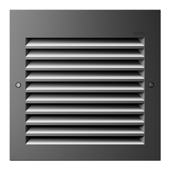
Recessed wall with louvers
Dimensions
A:
3 1/8 "
B:
3 1/8 "
C:
4 "
Replacement Parts
Description
Lens
Lens gasket
19 580
19 591
LED board
22 203
Part No
140425
830839.1
74020
22 203
06/2018
Page 1 of 2
Advertisement
Table of Contents

Subscribe to Our Youtube Channel
Related Manuals for BEGA 22 203


Summary of Contents for BEGA 22 203
- Page 1 74020 Lamp: 2.1W LED, 24V DC In the interest of product improvement, BEGA reserves the right to make technical changes without notice. 22 203 BEGA 1000 Bega Way, Carpinteria, CA 93013 (805)684-0533 Fax (805)566-9474 www.bega-us.com © Copyright BEGA-US 2018 06/2018...
- Page 2 CONVIENT AUX EMPLACEMENTS MOUILLÉS. LES FILS D’ALIMENTATION 90°C MIN. In the interest of product improvement, BEGA reserves the right to make technical changes without notice. BEGA 1000 Bega Way, Carpinteria, CA 93013 (805)684-0533 Fax (805)566-9474 www.bega-us.com © Copyright BEGA-US 2018...
Need help?
Do you have a question about the 22 203 and is the answer not in the manual?
Questions and answers