Table of Contents
Advertisement
Quick Links
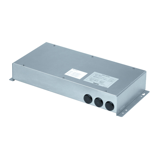
INSTALLATION INSTRUCTIONS
LonWorks Interface
Model No. CZ-CLNC1U
1.
2.
3.
4.
5.
6.
7.
8.
Note:
This equipment has been tested and found to comply with the limits for a Class B digital device, pursuant to part 15 of the FCC
Rules. These limits are designed to provide reasonable protection against harmful interference in a residential installation. This
equipment generates, uses and can radiate radio frequency energy and, if not installed and used in accordance with the instructions,
may cause harmful interference to radio communications. However, there is no guarantee that interference will not occur in a
particular installation. If this equipment does cause harmful interference to radio or television reception, which can be determined by
turning the equipment off and on, the user is encouraged to try to correct the interference by one or more of the following measures:
• Reorient or relocate the receiving antenna.
• Increase the separation between the equipment and receiver.
• Connect the equipment into an outlet on a circuit different from that to which the receiver is connected.
• Consult the dealer or an experienced radio/TV technician for help.
FCC Caution: To assure continued compliance, follow the attached installation instructions.
Any changes or modifi cations not expressly approved by the party responsible for compliance could void the user's authority to
operate this equipment.
LonWorks is a registered trademark of the Echelon Corporation.
85464369526011
Pana̲CZ-CLNC1U̲Eng.indd 1
Pana̲CZ-CLNC1U̲Eng.indd 1
- - Contents - -
2
4
5
6
7
8
9
10
11
12
15
2011/11/11 12:23:41
2011/11/11 12:23:41
Advertisement
Table of Contents

Related Manuals for Panasonic CZ-CLNC1U


Summary of Contents for Panasonic CZ-CLNC1U
-
Page 1: Table Of Contents
INSTALLATION INSTRUCTIONS LonWorks Interface Model No. CZ-CLNC1U – – Contents – – LonWorks Interface Overview Product Overview System Diagram Functions Installation Instructions of LonWorks Interface Safety Precautions Included Parts Installation Method Wiring Specifi cations LonWorks Interface Structure Power Board Initial Settings... -
Page 2: Lonworks Interface Overview
• Install a remote controller (or system controller, etc.), which can control the A/C units, to an inter-unit control wiring other than the LonWorks Interface unit. • Before making the connection to the LonWorks Interface unit, set the central control addresses in the indoor units. Pana̲CZ-CLNC1U̲Eng.indd 2 Pana̲CZ-CLNC1U̲Eng.indd 2 2011/11/11 12:23:41 2011/11/11 12:23:41... -
Page 3: Functions
(*6) When an alarm occurs at one or more indoor units, the alarm code is notifi ed as the indoor unit status. (*7) All the data which can be output is output at the set interval. (*8) The same data is not output continuously at the set interval. Pana̲CZ-CLNC1U̲Eng.indd 3 Pana̲CZ-CLNC1U̲Eng.indd 3 2011/11/11 12:23:41... -
Page 4: Installation Instructions Of Lonworks Interface
fi re. Main circuit board Node 2 Included Parts Main circuit board Node 1 Part Main circuit board Node 0 Power board Power transformer Installation Instructions Pana̲CZ-CLNC1U̲Eng.indd 4 Pana̲CZ-CLNC1U̲Eng.indd 4 2011/11/11 12:23:41 2011/11/11 12:23:41... -
Page 5: Power Board Initial Settings
• Before turning the power on, follow the instruction in Power Board Initial Settings. • When using the spare inter-unit cotrol line, connect [1] and [3] at CN002. • When using the spare LON communication line, connect [1] and [3] or [4] and [6] at CN003. Pana̲CZ-CLNC1U̲Eng.indd 5 Pana̲CZ-CLNC1U̲Eng.indd 5 2011/11/11 12:23:42 2011/11/11 12:23:42... -
Page 6: Indoor Unit Enabling Switches
• If using in combination with an ON/OFF controller, set the ON/OFF controller as the main if the ON/OFF controller’s remote-controller prohibit function is to be used. If this interface’s remote-controller prohibit function is to be used, set this interface as the main. Pana̲CZ-CLNC1U̲Eng.indd 6 Pana̲CZ-CLNC1U̲Eng.indd 6 2011/11/11 12:23:42 2011/11/11 12:23:42... -
Page 7: Communications Led (Green)
According to the test run mode specifi cations ⑭ ------ External 3-7/64 in.(H) × 19-11/16 in.(W) × 8-15/32 in.(D) ⑮ dimensions According to the version display specifi cations ⑯ Displays the A/C unit communications status Weight Approx. 7.27 lb. Pana̲CZ-CLNC1U̲Eng.indd 7 Pana̲CZ-CLNC1U̲Eng.indd 7 2011/11/11 12:23:42 2011/11/11 12:23:42... -
Page 8: Assigning Central Control Addresses
“7” is set as the central S004 control address for indoor unit group 2. For example, in this case Indoor unit address: 1-8 Central address: (5) Turn the power switch (S001) on the LonWorks Interface power board to ON. Pana̲CZ-CLNC1U̲Eng.indd 8 Pana̲CZ-CLNC1U̲Eng.indd 8 2011/11/11 12:23:42 2011/11/11 12:23:42... -
Page 9: Lonworks Interface Test Run
Indoor unit Gr Start/stop Start Data Start Stop 3 4 5 6 7 8 Stop S002 PUSH Indoor unit Gr STEP 4 Start/stop Start Data Start Start 3 4 5 6 7 8 Stop S002 PUSH Pana̲CZ-CLNC1U̲Eng.indd 9 Pana̲CZ-CLNC1U̲Eng.indd 9 2011/11/11 12:23:43 2011/11/11 12:23:43... -
Page 10: Checking The Lonworks Interface Version
Data digit of the LonWorks I/F microcomputer Next 3 seconds version 3 4 5 6 Data “0” Data Displays the third digit of the LonWorks I/F microcomputer version Last 3 seconds 3 4 5 6 Data Pana̲CZ-CLNC1U̲Eng.indd 10 Pana̲CZ-CLNC1U̲Eng.indd 10 2011/11/11 12:23:43 2011/11/11 12:23:43... -
Page 11: List Of Lonworks Network Variables
Indoor units with active alarms nvoAlarmIn_03 SNVT_switch Room temp. nvoSpaceTemp_03 SNVT_temp_p Indoor unit status nvoInState_03 SNVT_count Indoor groups 0 – 3 Input Emergency stop nviAllInOff SNVT_switch Transmission intervals settings nciSndHrtBt SNVT_time_sec Minimum time secured for transmission nciMinOutTm SNVT_time_sec Pana̲CZ-CLNC1U̲Eng.indd 11 Pana̲CZ-CLNC1U̲Eng.indd 11 2011/11/11 12:23:44 2011/11/11 12:23:44... -
Page 12: Details Of Lonworks Network Variables
Temperature settings are made in units of 1.0°C (1.8°F). (Values after the decimal point are discarded.) * Be aware that the temperature setting ranges may vary according to the models of the outdoor and indoor units. Pana̲CZ-CLNC1U̲Eng.indd 12 Pana̲CZ-CLNC1U̲Eng.indd 12 2011/11/11 12:23:44 2011/11/11 12:23:44... - Page 13 Swing (Not direction direction used) setting setting * Positions F4 and F5 can not be set for cool- Other Swing Stop and dry-mode operation. Filter sign is reset when Filter Filter data is updated. sign sign Pana̲CZ-CLNC1U̲Eng.indd 13 Pana̲CZ-CLNC1U̲Eng.indd 13 2011/11/11 12:23:44 2011/11/11 12:23:44...
- Page 14 These output network variables are output when the A/C unit each network variable. It is not valid between different network status changes. variables. They are output when the LonWorks Interface or A/C unit power is reset. Pana̲CZ-CLNC1U̲Eng.indd 14 Pana̲CZ-CLNC1U̲Eng.indd 14 2011/11/11 12:23:44 2011/11/11 12:23:44...
-
Page 15: Locations Where Neuron Id Is Applied
Node1 : 00 03 18 69 96 01 Node2 : 00 03 18 69 97 01 Node3 : 00 03 18 69 98 01 Main circuit board Neuron ID IC002 00 03 18 69 95 01 Indoor unit Address Setting SW enabling Pana̲CZ-CLNC1U̲Eng.indd 15 Pana̲CZ-CLNC1U̲Eng.indd 15 2011/11/11 12:23:44 2011/11/11 12:23:44... - Page 16 Printed in Japan Pana̲CZ-CLNC1U̲Eng.indd 16 Pana̲CZ-CLNC1U̲Eng.indd 16 2011/11/11 12:23:44 2011/11/11 12:23:44...
Need help?
Do you have a question about the CZ-CLNC1U and is the answer not in the manual?
Questions and answers