Table of Contents
Advertisement
Quick Links
Advertisement
Table of Contents

Related Manuals for Kobold KET


Summary of Contents for Kobold KET
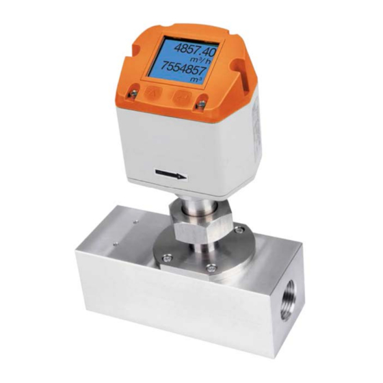
- Page 1 Operating Instructions Compact Inline Thermal Sensor Model: KET...
-
Page 2: Table Of Contents
Scaling Analogue output Compressed Air ..........8 Installation Description ................... 9 Installation of KET ................9 Display head position ................9 Flow measuring ranges ................10 Flow for different gases ..............10 ... - Page 3 Manufactured and sold by: Kobold Messring GmbH Nordring 22-24 D-65719 Hofheim Tel.: +49(0)6192-2990 Fax: +49(0)6192-23398 E-Mail: info.de@kobold.com Internet: www.kobold.com KET K01/0323 page 3...
-
Page 4: Note
Please read these operating instructions before unpacking and putting the unit into operation. Follow the instructions precisely as described herein. The instruction manuals on our website www.kobold.com are always for currently manufactured version of our products. Due to technical changes, the instruction manuals available online may not always correspond to the product version you have purchased. -
Page 5: Regulation Use
The user assumes all risk for such usage. The KET consumption sensor is used for continuous flow measurements. The KET consumption sensor is designed and constructed exclusively for the intended purpose described here and may only be used accordingly. -
Page 6: Safety Instructions
We offer you to take back the instruments of the instruments family KET which you would like to dispose of. Qualified employees from the measurement and control technology branch should only carry out adjustments and calibrations. -
Page 7: Operating Principle
6. Operating Principle The newly developed KET combines modern digital interfaces for connection to energy monitoring systems with a small, compact design. The KET is always used when many machines (compressed air consumers) are to be integrated into an energy monitoring network. -
Page 8: Scaling Analogue Output Compressed Air
Reference DIN1945/ ISO 1217: 20°C, 1000 mbar (Reference during calibration) Description Version Analogue output Low Speed 0...20 m³/h Standard 0...45 m³/h KET with integrated ½” measuring block 4… 20 mA = 0...90 m³/h High Speed 0...110 m³/h Low Speed 0...45 m³/h Standard 0...85 m³/h... -
Page 9: Installation Description
The connecting nut is tightened to a torque of 25 -30 Nm. It has to be checked whether the KET is correctly installed in the measuring section, the flow direction arrows must point from the integrated flow straightener away. -
Page 10: Flow Measuring Ranges
9. Flow measuring ranges 9.1 Flow for different gases Please note: The area outside the pipeline (ambient area of the sensor) must not be an explosive area. page 10 KET K01/0323... -
Page 11: Electrical Wiring
Modbus RTU A If no connection cable/ pulse cable is ordered the sensor will be supplied with a M12 connector plug. The user can connect the supply and signal cables as indicated in the connection diagram. KET K01/0323 page 11... -
Page 12: Operation
Alternatively, a 120R resistor can be installed in the plug between pin 2 and pin 4. 11. Operation Remark: Only for version with display The operation of the KET is done by the two capacitive key buttons Up () and Enter (... -
Page 13: Initialization
11.1 Initialization After switching on the KET, the initialized screen is displayed followed by the main menu. 11.2 Main menu Switching to pages 2-4 or back by pressing key “” AV-Time (Period for average value calculation) could be changed under Sensor Setup.-Advanced–... -
Page 14: Settings
For changes, first select the menu item with key „ “ and then confirm it with “OK“. 11.3.1.1 Input / change tube diameter For KET not adjustable (suspended) as voted on included measuring section with corresponding pipe diameter. page 14 KET K01/0323... - Page 15 In case the quantity of units selectable are not presentable on one page, pleas move to next page by pressing „<<“ . Confirm selection by pressing 2x „OK“. Procedure for all 4 measurement variables is analogous. KET K01/0323 page 15...
- Page 16 „OK“ . Setup Sensor Setup Advanced Ref.Temp By pressing „“ the position value is incremented by 1. Complete with "OK" and activate next number position. Procedure for changing the reference temperature is the same. page 16 KET K01/0323...
- Page 17 For average values see display window 3 + 4 11.3.1.5 Setting of Zero point and Low-flow cut off Setup Sensor Setup ZP Adjust 1,03 To make changes, first select a menu with button „“ and confirm selection by pressing „OK“ . KET K01/0323 page 17...
- Page 18 Setup Sensor Setup ZP Adjust t Reset By selection of „Reset“ all settings for „ZeroPnt“ and. „CutOff“ are reset. 1,03 Menu item to be select with button „“ and confirm the reset with „OK“ . Leave menu with button „Back“ page 18 KET K01/0323...
- Page 19 11.3.2 Modbus settings 11.3.2.1 Modbus RTU Setup The Flow sensors KET comes with a Modbus RTU Interface. Before commissioning the sensor, the communication parameters Modbus ID, Baudrate, Parity und Stop bit must be set in order to ensure the communication with the Modbus master.
- Page 20 Alternatively, a 120R resistor can be installed in the plug between pin 2 and pin 4. It must be ensured that the connection plugs are still plugged and the gasket is installed correctly, see also chapter 4.5. page 20 KET K01/0323...
- Page 21 1181 1180 Float Flow in cfm Flow in Ncfm 1189 1188 Float Flow in kg/h 1197 1196 Float Flow in kg/min 1205 1204 Float Flow in kg/s 1213 1212 Float Flow in kW 1221 1220 Float KET K01/0323 page 21...
- Page 22 Velocity NFt/min 1371 1370 Float GasTemp °C 1419 1418 Float GasTemp °F 1427 1426 Float Remark: For DS400 / DS 500 / Handheld devices - Modbus Sensor Datatype „Data Type R4-32“ match with „Data Type Float“ page 22 KET K01/0323...
- Page 23 1 m³ / Pulse 180000 3000 3000000 Table 1 Maximum flow for pulse output Entering pulse values that are not allow a presentation to the full scale value, are not allowed. Entries are discarded and error message displayed. KET K01/0323 page 23...
- Page 24 0000 (4 times zero). 11.3.4.2 Language Settings UserSetup Language Currently 4 languages have been implemented and could be selected with button „“ Change of language by confirming with “OK”. Leaving the menu with button “back”. page 24 KET K01/0323...
- Page 25 10s. To do this, use the "OK" button to enter the operating menu during this period 11.3.5 Advanced Settings Advanced By pressing „Factory Reset“ the sensor is set back to the factory settings. KET K01/0323 page 25...
- Page 26 „“ and confirm selection by pressing „OK“ . Settings 4‐20mA Channel 1 The 4-20 mA Analogue output of the Sensor KET can be individually adjusted. It is possible to assign following values „Temperature“, „Velocity“ und „Flow“ to the channel CH 1.
- Page 27 To make changes first select a menu item "Current Error" with button „“ and then select by pressing the „OK“ the desired mode For saving the changes done press button „Save“ to discard the changes press button “Cancel”. Leaving the menu with „Back“. KET K01/0323 page 27...
- Page 28 11.3.7 KET Info Settings Info Here you get a brief description of the sensor data incl. the calibration data. 92,7 m/s 600m³/h Under Details, you are able to see in addition the calibration conditions. Run Time: 2d 21h 23m 12s...
-
Page 29: Status / Error Messages
12. Status / Error messages 12.1 Status messages On the part of Kobold a regular re-calibration is recommended, see chapter 17. At delivery, the date at which the next recalibration is recommended is internally entered. When this date is reached, a message appears in the display with the status message „CAL“. -
Page 30: Maintenance
The sensor head should be checked regularly for dirt and cleaned if necessary. Should dirt, dust or oil accumulate on the sensor element, a deviation will occur in the measuring value. An annual check is recommended. Should the compressed air be heavily soiled this interval must be shortened. page 30 KET K01/0323... -
Page 31: Cleaning Of The Sensor Head
According to DIN ISO we recommend a calibration interval of one year for the instrument KET. On request and additional payment, calibration-certificates could be issued. The precision here is given and verifiable by the DKD-certified volume flow measuring devices. -
Page 32: Technical Information
18. Technical Information Operating instructions, data sheet, approvals and further information via the QR code on the device or via www.kobold.com 19. Order Codes Operating instructions, data sheet, approvals and further information via the QR code on the device or via www.kobold.com 20. -
Page 33: Disposal
(Cd, Hg, Li or Pb) of the heavy metal that is decisive for the classification as containing pollutants: 1. „Cd" stands for cadmium 2. „Hg" stands for mercury 3. „Pb" stands for lead 4. „Li" stands for lithium Electrical and electronic equipment KET K01/0323 page 33... -
Page 34: Eu Declaration Of Conformance
22. EU Declaration of Conformance We, KOBOLD Messring GmbH, Hofheim-Ts, Germany, declare under our sole responsibility that the product: Compact Inline Thermal Flow Sensor Model: KET-… to which this declaration relates is in conformity with the standards noted below: EN 61326-1:2013... -
Page 35: Declaration Of Conformity
23. UK Declaration of Conformity We, KOBOLD Messring GmbH, Hofheim-Ts, Germany, declare under our sole responsibility that the product: Compact Inline Thermal Flow Sensor Model: KET-… to which this declaration relates is in conformity with the standards noted below: BS EN 61326-1:2013 Electrical equipment for measurement, control and laboratory use.
Need help?
Do you have a question about the KET and is the answer not in the manual?
Questions and answers