Table of Contents
Advertisement
Advertisement
Table of Contents

Related Manuals for Kobold NGR


Summary of Contents for Kobold NGR
-
Page 2: Table Of Contents
Contents Contents level sensor ......................4 1.1 Principle of operation ................... 4 1.2 Safety notes ....................4 1.3 Fields of application ..................4 1.4 Installation conditions ................5 1.5 Electrical connection ................... 8 1.6 Display ......................8 1.7 Mounting the coaxial tube ................9 1.8 Shortening/replacing the probe ..............10 1.9 Mounting the probe rod ................12 2 Commissioning the... - Page 3 Contents 5.9 Selecting the display unit (millimeter/inch) ..........27 5.10 Setting the offset ..................28 6 Menu overview ......................29 7 Troubleshooting ......................37 7.1 Error message on the display ..............37 7.2 Operating the display ...................38 7.3 Outputs ......................39 7.4 Behavior ....................... 39 8 Technical data ......................
-
Page 4: Ngr Level Sensor
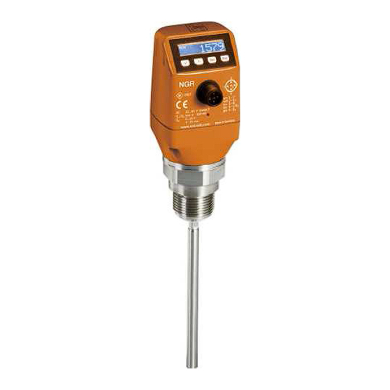
The NGR is suitable for both continual level measurement and limit level detection in nearly all liquids. It is not affected by changes in the properties of the liquids to be measured. The NGR can be used in metal containers or bypass/immersion pipes. A coaxial tube is required for use in plastic... -
Page 5: Installation Conditions
Minimum distances are also described in Diagrams 1 and 3. The NGR can also be used in a metal immersion pipe or bypass. The installation conditions are shown in Diagram 2. Ensure that there is a good metallic connection between the NGR measuring device and the tank/bypass. - Page 6 1 NGR level sensor Installation in a metal immersion tube or metal bypass D ≥ DN 40 Distance tank wall/tank bottom B ≥ 10 mm (0.40") center Diagram 2 Centering: To prevent contact between the probe and the bypass pipe during oscillations, the probe should be centered according to its length and depending on the diameter of the bypass pipe.
- Page 7 1 NGR level sensor Mono probe xing M = Measuring range X = No measuring possible in this area Rope probe mounted in metal tank Installation in nozzle: D ≥ DN 25 (1") Distance tank wall/tank bottom: A ≥ 50 mm (1.97") Distance to other tank fittings ≥...
-
Page 8: Electrical Connection
1 NGR level sensor 1.5 Electrical connection The sensor is connected using a pre-assembled female cable connector with 1 x M12 plug connector (5 or 8-pin). With the power switched off, plug the female cable connector into the sensor and screw it tight. -
Page 9: Mounting The Coaxial Tube
1 NGR level sensor Variants with four switching outputs Q1/2/3/4 1000 mm 39,4 in Arrow pushbuttons: For navigating in the menu and changing values Set pushbutton: For saving and confirming Esc pushbutton: For exiting the operating menu step-by-step 1.7 Mounting the coaxial tube Retrofitting of coaxial probe: Mount the spacer on the rod probe (first one at approx. -
Page 10: Shortening/Replacing The Probe
In this case, you should not shorten the probe beyond its minimum length of 100 mm. Procedure: Shorten the probe rod or cable probe* as desired. Set the new probe length in the NGR as described in Chapter “5.4 Configuring the probe length”. Ensure that this correction corresponds to the probe length, because an incorrect value in the Length menu has a direct effect on measurement accuracy and can lead to faults. - Page 11 1 NGR level sensor Shortening the cable probe* Cable weight Move cable weight to the desired length Move rope weight to the desired length Rope weight Tighten grub screws (1.5 Nm)* (3x) *We recomend to use thread locking fluid to secure the grub screws...
-
Page 12: Mounting The Probe Rod
1 NGR level sensor 1.9 Mounting the probe rod With the NGR, the probe rod can be modified by the customer. The specifications for the probe rod should be as follows: Probe rod diameter: 7 mm to 8 mm ■... -
Page 13: Commissioning The Ngr
2 Commissioning the NGR 2 Commissioning the NGR 2.1 Quick commissioning (with factory settings) Quick commissioning is used in applications under reference conditions (see Chapter 1.4 "Installa- tion conditions"). The following information applies: Use in metallic containers or immersion/bypass pipes ■... - Page 14 Access the EXPRT-CONFIG-CalRng menu using the arrow and Set pushbuttons. ○ The following information applies: ○ Teach-in depth starts from the NGR process connection ▫ ▫ Teach-in depth should cover all interference signals Maximum teach-in depth (recommended) = probe length ▫...
-
Page 15: Foam Commissioning (With Factory Settings)
200 mm from the process connection, however. 7. Adjust the sensitivity Exit the EXPRT menu with the ESC pushbutton. The NGR must now display a valid measured value. If the measured value is invalid, adjust the TrsHld value in the EXPRT-CONFIG menu. - Page 16 2 Commissioning the NGR Notes Measurement deviation can be higher ■ Signal quality 1 and 2 are not counted ■ The sensor automatically quits expert mode after 5 minutes of inactivity on the display. ■ Configuration (foam teach) does not take place in the following processes: ■...
-
Page 17: Con Iguring The Switching Outputs
3 Configuring the switching outputs 3 Configuring the switching outputs Diagramme1_EN.pdf 1 03.09.2014 14:40:59 3.1 Switching hysteresis and window function Depending on 2 or 4 output variants Level If the level is fluctuating around the set value (e.g., ripple movement during filling), the hyster- esis keeps the switching status of the outputs stable. -
Page 18: N/O Output With Con Igurable Hysteresis
3 Configuring the switching outputs 3.2 N/O output with configurable hysteresis Applications Dry run protection ■ Empty signal ■ Configuration Configure the Qx switching output as normally open ■ Set the parameter in the QxMENU-OUx menu to Qx_Hno ○ Set the switching point ■... -
Page 19: N/C Output With Con Igurable Hysteresis
3 Configuring the switching outputs 3.3 N/C output with configurable hysteresis Applications Overfill protection ■ Full signal ■ Configuration Configure the Qx switching output as normally closed ■ Set the parameter in the QxMENU-OUx menu to Qx_Hnc ○ Set the switching point ■... -
Page 20: N/O Output With Window Function
3 Configuring the switching outputs 3.4 N/O output with window function Application Thecritical filling level for the application is within the FHx and FLx window thresholds. Configuration Configure the Qx switching output as normally open ■ Set the parameter in the QxMENU-OUx menu to Qx_Fno ○... -
Page 21: N/C Output With Window Function
3 Configuring the switching outputs 3.5 N/C output with window function Application The critical filling level for the application is outside the FHx and FLx window thresholds. Configuration Configure Qx the switching output as normally closed ■ Set the parameter in the QxMENU-OUx menu to Qx_Fnc ○... -
Page 22: N/O Output With Error Signal
3 Configuring the switching outputs 3.6 N/O output with error signal Application If there is an error message at the NGR, this can be transferred using a switching contact. Configuration Configure the Qx switching output as normally open ■ Set the parameter in the QxMENU-OUx menu to Qx_Eno ○... -
Page 23: Con Iguring The Analog Output
4 Configuring the analog output 4 Configuring the analog output 4.1 Automatic signal detection The NGR can automatically detect which signal is required using the connected output load (see Chapter 9 "Technical data"). The following information applies: 4 mA to 20 mA < 500 ohms at Uv > 15 V ■... -
Page 24: Advanced Functions
○ Access the PASSW menu using the arrow pushbuttons ○ Enter password 000537 (NGR on mobile device keypad / L=5 / F=3 / P=7). If an incorrect password is entered or the device is switched off, expert mode is locked again. -
Page 25: Con Iguring The Probe Length
Even if there is no liquid in the container yet, it is possible to select a filling level in the menu in ■ order to test the sensor configuration. When simulating a level value, all outputs on the NGR are set according to the defined configuration. The function should not be selected until a configuration is complete. -
Page 26: Evaluating Signal Quality
○ Maximum value = probe length – 100 mm ○ AutCal function must be run after this (see Chapter 2 "Commissioning the NGR") ○ The CalRng parameter should always correspond to the probe length for NGRs with remote amplifier ○... -
Page 27: Changing The Coaxial Cable Length
5 Advanced functions 5.7 Changing the coaxial cable length (in preparation) Valid for versions with remote amplifier. ■ This setting makes it possible to configure the coaxial cable length between the sensor head and ■ process connection. Configuration Predefined coaxial cable length (1,000 mm, 2,000 mm, or 3,300 mm) ■... -
Page 28: Setting The Offset
5 Advanced functions 5.10 Setting the offset This setting makes it possible to indicate the level value on the display in relation to the tank ■ bottom instead of the end of the probe. The actual container level is then indicated on the display. Configuration Log into expert mode (see Chapter “5.1 Expert mode”) ■... -
Page 29: Menu Overview
QAMENU QAHIGH Value QALOW Value QAPOL Para QATYP Para Menu overview continues on page 30. Note: Q3 and Q4 are only available for an NGR with four switching outputs. 1) Elements which are displayed depend on the OUx parameer selection. - Page 30 6 Menu overview Description Parameter See Chapter 2 "Commissioning the NGR" AutCal Q1MENU, Q2MENU, See Chapter 3 "Configuring the switching outputs" Q3MENU, Q4MENU Switching point, switching output 1 or 2 or 3 or 4 (SPx > RPx) Note: Not displayed if the switching output in the OUx menu is set to error or window.
- Page 31 6 Menu overview QAFAIL Para SimCur Para SimVol Para DspVal Para Filter Para SimLev Para RstFac CALL.. Menu overview continues on page 32. 2) Elements which are displayed depend on the QATYP parameter selection.
- Page 32 6 Menu overview Description Parameter QAFAIL Output behavior as per NE43 in the event of a fault (function only available when current output has been selected under QATYP). 3.5 mA = Analog current output is set to 3.5 mA in the event of a fault ●...
- Page 33 6 Menu overview EXPRT Value Config TrsHld Offset Value MaxCol Value MeasMd Para Length Value CalRng Value CblLen Value Lock Para Unit Para Foam CalEmp Cal.OK CalMed Cal.OK Cal.OK FomSta Value Limit Menu overview continues on page 34. Password-protected measuring range.
- Page 34 6 Menu overview Parameter Description EXPRT See Chapter 5.1 "Expert mode" TrsHld This value describes a factor which determines how strong an echo has to be in order to be recognized by the device. The value range lies between 20% and 500%.
- Page 35 6 Menu overview FrmVer Value Info SerNo Value CalSta Value TagNam Value SigQua SigQa1 Value SigQa2 Value SigQa3 Value StEcho PASSW Value...
- Page 36 6 Menu overview Description Parameter Info Sensor information FrmVer Shows the firmware version SerNo Shows the serial number CalSta Displays the status of the container calibration Initia = Container calibration not carried out ● Calibr = Container calibration activated ● Only shown if password entered.
-
Page 37: Troubleshooting
7 Troubleshooting 7 Troubleshooting 7.1 Error message on the display Error Cause Solution !InvEc AutCal not executed, interference Perform commissioning superimposes medium reflection & (see Chapter 2.1 "Quick commissioning") level present TrsHld setting is not suitable for the Perform advanced commissioning medium (see Chapter 2.2 "Advanced commissioning") !InvEc... -
Page 38: Operating The Display
7 Troubleshooting Error Cause Solution !Range The maximum allowable measuring Reduce probe length and/or coaxial cable range was exceeded. Measurement in length (see Chapter “5.7 Changing the coaxial this configuration is not possible. cable length”) !Cable The coaxial cable is damaged/faulty Replace the coaxial cable The coaxial cable length was config- See Chapter 5.7 "Changing the coaxial cable... -
Page 39: Outputs
Sensor shows high level after AutCal not performed Perform commissioning installation even though the tank (see Chapter 2 is empty "Commissioning the NGR") When used with a coaxial tube, AutCal not performed Perform commissioning the sensor indicates a high level (see Chapter 2 although the tank is empty "Commissioning the NGR") - Page 40 Perform commissioning again Change in the ambient conditions regarding the situation during the (see Chapter 2 AutCal process "Commissioning the NGR") Significant buildup of foam Perform foam commissioning (see Chapter 2.3 "Foam commis- sioning") TrsHld set too low, the echo...
-
Page 41: Technical Data
8 Technical data 8 Technical Data 8.1 Features Medium Liquids Limit, continuous Detection type Probe length Mono-rod probe 200 mm to 2,000 mm Cable probe* 1,000 mm, 2,000 mm, 3,000 mm, 4,000 mm Adjustable measuring range 95 mm to 6,005 mm Process pressure –1 bar to 10 bar Process temperature... -
Page 42: Reference Conditions
8 Technical data Dielectric constant ≥ 5 for mono-rod probe/cable probe* ≥ 1.8 with coaxial tube Conductivity No limitation Maximum change of level 500 mm/s Inactive area at process connection 25 mm Inactive area at end of probe 10 mm With water under reference conditions. -
Page 43: Measurement Accuracy
8 Technical data 8.4 Measurement accuracy Measurement accuracy with parameterized container Probe length in mm L-10 Probe length in mm L-100 (in preparation) - Page 44 8 Technical data Measurement accuracy without parameterized container Inactive area Probe length in mm L-10 Inactive area Probe length in mm L-100 (in preparation)
-
Page 45: Mechanics/Materials
8 Technical data 8.5 Mechanics/materials Wetted parts 1.4404, PTFE Process connection G 3/4 A, 3/4'' NPT Housing material Plastic PBT Max. probe load ≤ 6 Nm Enclosure rating IP67: EN 60529 Weight Max. 1.3 kg Coaxial cable insulation 8.6 Electrical connection values Supply voltage 12 V DC to 30 V DC 1) 2) -
Page 46: Environmental Conditions
8 Technical data 8.7 Environmental conditions Ambient temperature, opera- –20°C to +60°C tion Ambient temperature, storage –40°C to +80°C According to UL listing: degree of contamination 3 (UL61010-1: 2012-05); air humidity: 80% at temperatures up to 31 °C; installation height: max. 3,000 m above sea level; indoor applications only 8.8 Dimensional drawings Dimensions in mm (1.97) - Page 47 8 Technical data Standard version* (1.97) 36 (1.42) M12x1 G 3/4 A 3/4" NPT (0.20) 3 (0.11) M: Measuring range L: Probe length IA: Inactive area at process connection 25 mm IAE: Inactive area at probe end 10 mm (0.94) * in preparation...
- Page 48 8 Technical data NGR Inox with remote amplifier* (4.72) (1.42) G 3/4 A 3/4" NPT (0.20) 36 (1.42) 7 (0.28) (1.57) 70 (2.76) 43 (1.69) C: Cable length M: Measuring range (1.30) L: Probe length IA: Inactive area at process connection...
-
Page 49: Factory Settings
8 Technical data 8.9 Factory settings Parameter Factory setting 80% of the probe length measured from the end of the probe 5 mm below SP1 Q1_Hno For 5-pin versions: 20% of the probe length measured from the end of the probe For 8-pin versions: 60% of the probe length measured from the end of the probe 5 mm below SP2 Q2_Hno... -
Page 50: Accessories
9 Order Details 9 Order Details... -
Page 51: Maintenance
This medium list (from page 56) provides an overview of the DK values of liquids. Water-based liquids always have a DK value of > 5, which allows NGR to be used easily. For DK values of < 5, a coaxial tube or a metallic immersion tube/bypass is always required. - Page 52 13 Medium list Substance Substance Substance value value value Acetal (25°C) Formic acid 57.9 Benzaldehyde 17.6 Acetaldehyde 15.0 Ammonia 15.0 Benzil (80°C) 10.0 Acetamide (77°C) 59.2 Ammonia solution (25%) 31.6 Benzine Acetoacetic acid ethyl 15.0 Ammonia salt Benzene ester Acetone 21.5 Pentanol 14.8...
- Page 53 13 Medium list Substance Substance Substance value value value Chloral Ice cream (-20°C) 16.5 Ferrozell 18.3 Chlorobenzine Iron (III) oxide red Fat coal Chloracetic acid 33.4 Emulphor Fatty acid (35°C) Chlorohydrin 31.0 Epichlorhydrin 23.0 Fish oil Chlorinated lime Peanuts, dried Flax pellets Chloroform (trichlormeth- Peanut expeller...
- Page 54 13 Medium list Substance Substance Substance value value value Glycerol water 37.0 Splints Isosafrol Glycol 37.0 Honey 24.0 Iodine 11.1 Glysantin 25.0 Hydrazine 58.0 Iodobenzene Granuform Imidazole, pure (100°C) 23.0 Methyl iodide Guaiacol 11.0 Isoamyl acetate Hydrogen iodide Guano (phosphate rock) Isoamyl alcohol 15.6 Coffee beans...
- Page 55 13 Medium list Substance Substance Substance value value value Cork powder Flour Nitroglycol 28.3 Concentrated feed Molasses 31.3 Nitroglycerin 19.3 Chalk Menthol (42°C) Nitro varnish Cresol 11.0 Mesityl oxide 15.0 Nitromethane 39.0 Cresol resin 18.3 Metal powder Nitrophoska Crystal sugar Methanol (methyl alcohol) 33.0 Nitrosyl bromide (13°C)
- Page 56 13 Medium list Substance Substance Substance value value value Penta ethyl chloride Liquid detergent Nitric acid (98%) 19.0 Penta chlorotoluene Propanal (15°C) 14.4 Hydrochloric acid Pentane Propanol (propyl alcohol ) Salt water 32.0 Pentanal (15°C) 11.8 Propanoic acid Oxygen Pentene Propylamine Chamotte Perchlorate...
- Page 57 13 Medium list Substance Substance Substance value value value Silicone rubber Transformer oil Toothpaste 18.3 Soy flour Trichloroethylene Cellulose Soy grains Triethyl aluminum Cement Sunflower seeds Triptan Zinc oxide Chaff Dry yeast Zinc powder Stearic acid Ultrasil Sugar Rock salt (0–25 mm) Undecan Tinder 12.0...
-
Page 58: Eu Declaration Of Conformance
14 EU Declaration of Conformance 14 EU Declaration of Conformance We, KOBOLD Messring GmbH, Hofheim-Ts, Germany, declare under our sole responsibility that the product: Level Sensor Model: NGR to which this declaration relates is in conformity with the standards noted below:... - Page 59 Manufactured and sold by: Kobold Messring GmbH Nordring 22-24 D-65719 Hofheim Tel.: +49(0)6192-299-0 Fax: +49(0)6192-23398 E-Mail: info.de@kobold.com Internet: www.kobold.com Version: K03/0517...
Need help?
Do you have a question about the NGR and is the answer not in the manual?
Questions and answers