Clean Water Systems 7800 Installation & Start?Up Manual
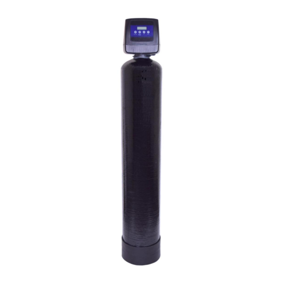
Neutralizer
Hide thumbs
Also See for 7800:
- Installation & start?up manual (13 pages) ,
- Installation & start?up manual (13 pages)
Table of Contents
Advertisement
Quick Links
Clean Water Made Easy
www.cleanwaterstore.com
7800 Neutralizer Installation & Start-Up Guide
Thank you for purchasing a Clean Water System! With proper installation and a
little routine maintenance your system will be providing neutral pH water for
many years.
Please review this start-up guide entirely before beginning to install your system
and follow the steps outlined for best results.
CALCITE MEDIA CONTAINS DUST. USE PAPER MASK AND VENTILATE TO AVOID
BREATHING DUST.
Questions?
Call us toll-free: 1-888-600-5426 or 1-831-462-8500
Email us:
support@cleanwaterstore.com
See more information on our website:
www.cleanwaterstore.com/resources
Advertisement
Table of Contents

Subscribe to Our Youtube Channel
Related Manuals for Clean Water Systems 7800


Summary of Contents for Clean Water Systems 7800
- Page 1 Clean Water Made Easy www.cleanwaterstore.com 7800 Neutralizer Installation & Start-Up Guide Thank you for purchasing a Clean Water System! With proper installation and a little routine maintenance your system will be providing neutral pH water for many years. Please review this start-up guide entirely before beginning to install your system and follow the steps outlined for best results.
-
Page 2: Table Of Contents
How Your Neutralizer Works ..........................5 Fig 1 - Neutralizer Filter Tank Water Flow ..................5 Fig 2 - Typical Neutralizer 7800 piping installation with ball valve and hose bib after the filter..6 Fig 5: 7800 By-Pass and Pipe Connectors ..................9 Initial Programming ............................ -
Page 3: Packing List
7800 Neutralizer Installation & Startup Guide Packing List Neutralizer 1.0 cubic foot size 7800 Backwash Control Valve w/ Bypass Assembly and Pipe connector kit (1”or ¾”) 10” x 44” filter tank with distributor tube Blue media funnel for adding the Calcite media 12lbs. -
Page 4: Pre-Installation
1. See typical installation on page 7 (Fig 2). The Neutralizer is installed after the pressure tank. 2. Make sure to connect the IN pipe to the 7800 inlet and the OUT pipe to the outlet (see Fig 2). As you face the 7800 control from the front, the water enters on the right and exits on the left. -
Page 5: How Your Neutralizer Works
7. The drain line tubing (not supplied) is connected to a drain from the drain outlet using flexible ½” ID tubing. Note that the drain can run up above the 7800 control and into a drain, it does not have to drain down, as the filter backwashes under line pressure from your well pump. Most plumbing codes require an air-gap connection, so that if your sewer or septic tank backs up, it cannot cross connect with the drain tubing. -
Page 6: Fig 2 - Typical Neutralizer 7800 Piping Installation With Ball Valve And Hose Bib After The Filter
7800 Neutralizer Installation & Startup Guide Fig 2 - Typical Neutralizer 7800 piping installation with ball valve and hose bib after the filter Page 6 www.cleanwaterstore.com Rev 120215... - Page 7 7800 Neutralizer Installation & Startup Guide Fig 3: 7800 from the rear showing the inlet (left) and outlet (right) end- connector fittings 3/4” or 1” NPT in Noryl plastic. Brass end-connectors are also available for connecting to copper tubing. Fig 4 7800 Bypass and Service Mode Positions Page 7 www.cleanwaterstore.com...
- Page 8 Assembly and Installation Instructions 1. By hand, unscrew the entire 7800 control valve from the top of the tank if it was shipped screwed on. Place distributor tube in tank if not already inside. If not already done, make sure the blue cap is on top of distributor tube, or wrap the top of distributor tube with electrical or duct tape.
-
Page 9: Fig 5: 7800 By-Pass And Pipe Connectors
(#3). 11. Note that the 7800 is usually shipped in the bypass position. There is a bypass valve knob on both the inlet and the outlet. You can easily tell if it is in bypass because the two knobs will be in line with each other (Fig 4). -
Page 10: Initial Programming
7800 Neutralizer Installation & Startup Guide 7800 Neutralizer up to 4 feet above the top of the tank. If the drain line will be more than 20 feet, use larger diameter tubing such as ¾” or 1”. Note that it is desirable to be able to run the drain line into a bucket in order to test the backwash flow rate in the future. -
Page 11: Starting The Initial Backwash
First open the Inlet Side of the bypass valve. Second slowly open the Outlet Side of the bypass until it is in the full service position. The 7800 bypass valve knobs are a little stiff, so you can use Allen wrench placed in the holes to turn the knobs. Turn the bypass valve knobs in the correct direction which is counter-clockwise as you face the bypass valve knobs. -
Page 12: How To Add Calcite Media To The 7800 Neutralizer Filter
7800 Neutralizer Installation & Startup Guide 2.5 Cubic Foot Model: 13.0 GPM minimum 15 GPM recommended 16. The next cycle is the Rinse cycle and this runs for 6 to 8 minutes. After the backwash, the 7800 will automatically advance to the rinse cycle. -
Page 13: When To Use Calcite Blends
7800 Neutralizer Installation & Startup Guide When to Use Calcite Blends If the water pH is less than 6.0, Calcite alone may not be enough to bring the pH up to the desired range of 7.0 to 7.8. In this case, a blend of Calcite and Corosex should be used. Calcite is a calcium media consisting of calcium carbonate and will raise the pH slowly. -
Page 14: Neutralizers 2.5 Cubic Foot: Use 200 Lbs Calcite And 20 Lbs Corosex
7800 Neutralizer Installation & Startup Guide Corosex 10 lbs (1 10 lb boxes) .13 cu ft Neutralizers 1.5 Cubic Foot:use 150 lbs Calcite and 10lbs Corosex Your new 1.5 Cubic Foot Neutralizer Blend filter includes: Calcite 150 lbs (3 50-lb boxes) 1.65 cu ft ... -
Page 15: White Spots On Fixtures And Glasses
Neutralizer filter is a drop in water pressure, due to fouling of the media from rust or sediment. You can verify the backwash flow rate by running the drain line into a bucket and timing it when the 7800 is in Cycle 1 or backwash. - Page 16 7800 Neutralizer Installation & Startup Guide 3) The valve will advance to the BW (backwash) position, and start counting down. Press the Regen button again, and wait for the valve to advance and stop at the Rapid Rinse (RR) position.
Need help?
Do you have a question about the 7800 and is the answer not in the manual?
Questions and answers