
Related Manuals for Gree U-Match 6 Series


Summary of Contents for Gree U-Match 6 Series
- Page 1 U-Match 6 SERIES UNIT SERVICE MANUAL (GC202204-I) Capacity: 3.5kW~16.0kW Rate Frequency: 50/60Hz Operation Range: -20℃~52℃...
- Page 2 Foreword Thank you for choosing Gree U-Match air conditioners. In order to correctly install and use our units, and for the satisfactory operation effect, please read this manual carefully. This manual specifies safe operation requirements from perspectives of product introduction, control, troubleshooting and maintenance, as well as basic principles and implementation methods.
-
Page 3: Table Of Contents
CONTENTS Safety Notice on Maintenance ...................... 1 Safety Notice on Operation ......................4 1. Product Introduction ......................... 6 1.1 Lists of Units ............................6 1.2 Electrical Parameters ........................11 2. Control ............................12 2.1 Operation Mode ..........................12 2.2 Control Mode ........................... 13 2.3 Functions ............................ -
Page 4: Safety Notice On Maintenance
GREE U-Match 6 SERIES UNIT SERVICE MANUAL Safety Notice on Maintenance PROHIBITED: (1) Do not pierce or burn. (2) Please note that refrigerant may be odorless. (3) The appliance shall be stored in a room without continuously operating ignition sources (For example: open flames, an operating gas appliance or an operating electric heater). - Page 5 GREE U-Match 6 SERIES UNIT SERVICE MANUAL (6) If you need to carry out maintenance or check the electric circuit without cutting off the power, please be careful not to touch the electrical parts. (7) Any person who is involved with working on or breaking into a refrigerant circuit should hold a...
- Page 6 GREE U-Match 6 SERIES UNIT SERVICE MANUAL concentration of refrigerant from exceeding the allowable safety limit; Excessive refrigerant leakage may lead to explosion. (22) When installing or re-installing the air conditioner, please keep the refrigerant circuit away from substances other than the specified refrigerant, such as air. Any presence of foreign substances will cause abnormal pressure change or even explosion, resulting in injury.
-
Page 7: Safety Notice On Operation
GREE U-Match 6 SERIES UNIT SERVICE MANUAL (13) Never stop the air conditioner by directly cutting off the power. (14) Please select the proper copper pipe according to the requirement for pipe thickness. (15) Adopt proper measures to protect the outdoor unit from small animals because they may damage the electric components and cause malfunction of the air conditioner. - Page 8 GREE U-Match 6 SERIES UNIT SERVICE MANUAL WARNING: (1) If the power plug is dirty, please clean it before inserting it to the power socket. If the power plug is loose, please tighten it up. (2) Do not damage the power cord. A damaged or refitted power cord may lead to electric shock or fire hazard.
-
Page 9: Product Introduction
GREE U-Match 6 SERIES UNIT SERVICE MANUAL 1. Product Introduction 1.1 Lists of Units 1.1.1 List of ODUs Power Supply Model Finished Product Code Appearance V/Ph/Hz GUD35W1/NhA-S CF090W2182 GUD35W1/NhA-S(LCLH) CF090W2181 GUD50W1/NhA-S CF090W2160 GUD50W1/NhA-S(LCLH) CF090W2161 GUD71W1/NhA-S CF090W2170 GUD71W1/NhA-S(LCLH) CF090W2171 220-240V ~50/60Hz... - Page 10 GREE U-Match 6 SERIES UNIT SERVICE MANUAL Power Supply Model Finished Product Code Appearance V/Ph/Hz GUD100W1/NhA-X CF090W2340 GUD100W1/NhA-X(LCLH) CF090W2341 GUD125W1/NhA-X CF090W2190 GUD125W1/NhA-X(LCLH) CF090W2191 GUD140W1/NhA-X 380-415V 3N~50/60Hz CF090W2230 GUD140W1/NhA-X(LCLH) CF090W2231 GUD160W1/NhA-X CF090W2470 GUD160W1/NhA-X(LCLH) CF090W2471 Note: LCLH mean the outdoor unit with electrical heater on the chassis.
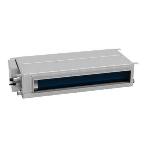
- Page 11 GREE U-Match 6 SERIES UNIT SERVICE MANUAL 1.1.2 List of IDUs Rated Cooling/ Power Supply Finished Model Hating Capacity Appearance Product Code (kW) V/Ph/Hz GUD35T1/A-S 3.50/4.00 ET010N2320 GUD50T1/A1-S 5.00/5.60 ET010N2440 GUD50T1/A-S 5.30/5.80 ET010N2310 GUD71T1/A-S 7.10/8.00 ET010N2330 GUD85T1/A-S 8.50/8.80 ET010N2480 Cassette...
- Page 12 GREE U-Match 6 SERIES UNIT SERVICE MANUAL Rated Cooling/ Power Supply Finished Model Hating Appearance Product Code Capacity (kW) V/Ph/Hz GUD35P1/A-S CF022N3970 3.50/4.00 CF022N3980 GUD35PS1/A-S GUD50P1/A-S CF022N3960 5.30/5.60 GUD50PS1/A-S CF022N3950 GUD71PH1/A-S CF022N3930 7.10/8.00 GUD71PHS1/A-S CF022N3940 GUD85PH1/A-S CF022N4310 8.50/8.80 GUD85PHS1/A-S CF022N4301...
- Page 13 GREE U-Match 6 SERIES UNIT SERVICE MANUAL Rated Cooling/ Power Supply Finished Model Hating Capacity Appearance Product Code (kW) V/Ph/Hz GUD35ZD1/A-S 3.50/4.00 ED020N2380 GUD50ZD1/A-S 5.30/5.60 ED020N2370 GUD71ZD1/A-S 7.10/7.70 ED020N2360 GUD85ZD1/A-S 8.50/8.80 ED020N2490 Floor 220-240V Ceiling ~50/60Hz Type GUD100ZD1/A-S 10.00/11.50 ED020N2450 GUD125ZD1/A-S 12.10/13.50...
-
Page 14: Electrical Parameters
GREE U-Match 6 SERIES UNIT SERVICE MANUAL 1.2 Electrical Parameters Circuit breaker Min. sectional area of Power supply capacity power cord Model V/Ph/Hz GUD35W1/NhA-S GUD50W1/NhA-S GUD71W1/NhA-S GUD85W1/NhA-S 220-240V ~50/60Hz GUD100W1/NhA-S GUD125W1/NhA-S GUD140W1/NhA-S GUD100W1/NhA-X GUD125W1/NhA-X 380-415V 3N~50/60Hz GUD140W1/NhA-X Circuit Breaker Min. Sectional Area of... -
Page 15: Control
GREE U-Match 6 SERIES UNIT SERVICE MANUAL 2. Control 2.1 Operation Mode 2.1.1 Cooling Mode Note: The cassette and floor ceiling type indoor fan run after outdoor fan. -
Page 16: Control Mode
GREE U-Match 6 SERIES UNIT SERVICE MANUAL 2.1.2 Heating Mode Power on Heating start control Satisfying open Comp.condition Comp. and outdoor fan Comp. and Comp. stop outdoor fan for 3 min stop Avoid cool wind indoor fan run for 1 min... - Page 17 GREE U-Match 6 SERIES UNIT SERVICE MANUAL 2.2.1.2 EXV Control When the unit is first started, the electronic expansion valve will reset control. During the process, the expansion valve will produce rattling sound. When cooling or heating mode is turned on, the valve will be open at a certain step before the compressor starts.
- Page 18 GREE U-Match 6 SERIES UNIT SERVICE MANUAL frequency. 2.2.2.3 Refrigerant Recovery Control Enabling method: Remote controller and wired controller both use the same enabling method. That is, within 5min after power is connected, start cooling mode (turn on the unit) and set temperature at 16 ℃ , then press “+, -, +, -, +, -”...
- Page 19 GREE U-Match 6 SERIES UNIT SERVICE MANUAL 2.2.3 Protection Control 2.2.3.1 High Pressure Protection Control (Only for 100/125/140/160 units) System will enable high pressure protection control if the high pressure switch is detected open for continuously a little time. Under high pressure protection, system will be shut down and display error code When high pressure protection occurs for the first time, system will restore operation if the high pressure switch is detected to be reclosed for continuously a little time.
-
Page 20: Functions
GREE U-Match 6 SERIES UNIT SERVICE MANUAL 2.3 Functions 2.3.1 Setting of Filter Cleaning Reminder Turn on Filter Clean Reminder Function: When unit is on, press “FUNCTION” button and select Filter Clean Reminder. “ ” icon will blink. Press “+” or “-” button to adjust the cleaning level, of which the range is 00, 10-39. - Page 21 GREE U-Match 6 SERIES UNIT SERVICE MANUAL When low-temperature dry function is turned on, directly press “+” button or switch the mode can quit the function. 2.3.3 Child-lock Function Without error, under ON or OFF status of unit, press “+” and “-” buttons simultaneously for 5 seconds can enter into child-lock function, the liquid crystal screen will display “...
- Page 22 GREE U-Match 6 SERIES UNIT SERVICE MANUAL ON/OFF of unit can be controlled. If long-distance monitoring or centralized controller information is received when the room card is not inserted, the icon is cleared. When the card is reinserted, door control function is judged to be turned on. If long-distance monitoring or centralized controller information is received when the room card is inserted, it will keep the original status.
- Page 23 GREE U-Match 6 SERIES UNIT SERVICE MANUAL The specific error code will blink at temperature displaying zone. The 5th displayed malfunction is the last malfunction. (2) Inquiry of historical malfunction of outdoor unit: press “+” or “-” button to select parameter code “n6”.
- Page 24 GREE U-Match 6 SERIES UNIT SERVICE MANUAL to select parameter code to “P21”. Press “MODE” button to enter parameter setting. At that time, parameter value is blinking at time displaying zone. Press “+” or “-” button to adjust the parameter value and press “ENTER” button to finish setting. The compensation value setting range is -15 to 15.
- Page 25 GREE U-Match 6 SERIES UNIT SERVICE MANUAL ② The default ESP mode setting is P05 which is the rated ESP. ③ The remote controller can be used to change turbo, H, M and L. There are 9 selections for high static pressure (ESP) duct: (1) P1 (LCD displays 01).
- Page 26 GREE U-Match 6 SERIES UNIT SERVICE MANUAL (3) Press “+” or “-” button to select parameter code to “P13”. Press “MODE” button to enter parameter setting. At that time, parameter value is blinking at time displaying zone. Press “+” or “-”...
- Page 27 GREE U-Match 6 SERIES UNIT SERVICE MANUAL 2.3.13.3 Selecting door control function Under debugging state, press “+” or “-” button to select parameter code to “02” in temperature displaying zone. Timer zone displays setting state and press “+” or “-” button to adjust. There are 2 selections: (1) Without door control function (LCD displays 00).
- Page 28 GREE U-Match 6 SERIES UNIT SERVICE MANUAL displaying zone. Timer zone displays setting state and press “+” or “-” button to adjust. There are 2 selections: Mode 1 (LCD displays 00). Mode 2 (LCD displays 01). Press “ENTER” button to finish setting.
- Page 29 2.3.15 Connect to Interface of the MODBUS The indoor unit of this series has MODBUS interface. If the user needs to connect the unit to the management system of the building, please enquire Gree for the MODBUS protocol.
- Page 30 GREE U-Match 6 SERIES UNIT SERVICE MANUAL (1) Interface instruction: 1) The Unit needs to be connected to the gateway ME50-00/EG(M), its printing is COM_BMS and interface type is B6B-XH-K3. 2) Electrical characteristic: baud rate: 9600bps; standard: RS485; 3) Working principle: The indoor mainboard can send out the unit operation state through this interface and receive logical control information to realize control and monitor of the unit.
-
Page 31: Troubleshooting
GREE U-Match 6 SERIES UNIT SERVICE MANUAL 3. Troubleshooting 3.1 Wiring Diagrams The following electric diagram is for reference only. Please refer to diagram sticked on the unit as the latest version. 3.1.1 Wiring Diagrams of ODUS Model: GUD35W1/NhA-S... - Page 32 GREE U-Match 6 SERIES UNIT SERVICE MANUAL Model: GUD50W1/NhA-S, GUD71W1/NhA-S...
- Page 33 GREE U-Match 6 SERIES UNIT SERVICE MANUAL Model: GUD85W1/NhA-S Model: GUD100W1/NhA-S,GUD125W1/NhA-S...
- Page 34 GREE U-Match 6 SERIES UNIT SERVICE MANUAL Model: GUD140W1/NhA-S Model: GUD100W1/NhA-X, GUD125W1/NhA-X...
- Page 35 GREE U-Match 6 SERIES UNIT SERVICE MANUAL Model: GUD140W1/NhA-X 3.1.2 Wiring Diagrams of IDUs Cassette Type Model: GUD35T1/A-S,GUD50T1/A1-S...
- Page 36 GREE U-Match 6 SERIES UNIT SERVICE MANUAL Model: GUD50T1/A-S,GUD71T1/A-S,GUD85T1/A-S Model: GUD100T1/A-S,GUD125T1/A-S,GUD140T1/A-S...
- Page 37 GREE U-Match 6 SERIES UNIT SERVICE MANUAL Duct Type Model: GUD35P1/A-S,GUD35PS1/A-S Model: GUD50P1/A-S,GUD50PS1/A-S...
- Page 38 GREE U-Match 6 SERIES UNIT SERVICE MANUAL Model: GUD71PH1/A-S,GUD85PH1/A-S,GUD71PHS1/A-S,GUD85PHS1/A-S Model: GUD100PH1/A-S,GUD125PH1/A-S,GUD100PHS1/A-S,GUD125PHS1/A-S...
- Page 39 GREE U-Match 6 SERIES UNIT SERVICE MANUAL Model: GUD140PH1/A-S,GUD140PHS1/A-S Floor Ceiling Type Model: GUD35ZD1/A-S, GUD50ZD1/A-S, GUD71ZD1/A-S, GUD85ZD1/A-S, GUD125ZD1/A-S, GUD140ZD1/A-S...
- Page 40 GREE U-Match 6 SERIES UNIT SERVICE MANUAL Model: GUD100ZD1/A-S...
-
Page 41: Pcb Layout
GREE U-Match 6 SERIES UNIT SERVICE MANUAL 3.2 PCB Layout 3.2.1 Interface Indoor unit: Model:GUD35P1/A-S,GUD50P1/A-S,GUD35PS1/A-S,GUD50PS1/A-S Printing Interface Printing Interface PUMP water pump COM-OUT ODU communication interface Live wire input Neutral wire input Ground wire Motor output HEALTH Cold plasma interface... - Page 42 GREE U-Match 6 SERIES UNIT SERVICE MANUAL Model: GUD71PH1/A-S,GUD85PH1/A-S,GUD100PH1/A-S,GUD125PH1/A-S,GUD71PHS1/A-S, GUD85PHS1/A-S,GUD100PHS1/A-S,GUD125PHS1/A-S Printing Interface Printing Interface PUMP water pump ODU communication interface Live wire input Neutral wire input Ground wire motor output HEALTH Cold plasma interface HEAT Electric heating interface Ambient temperature sensor...
- Page 43 GREE U-Match 6 SERIES UNIT SERVICE MANUAL Model: GUD140PH1/A-S,GUD140PHS1/A-S Printing Interface Printing Interface Reactor Reactor Ground wire Live wire input Neutral wire input PUMP water pump ODU communication COM-OUT WIFI WiFi interface interface Ambient temperature sensor COM-BMS MODBUS gateway interface...
- Page 44 GREE U-Match 6 SERIES UNIT SERVICE MANUAL Model:GUD35ZD1/A-S,GUD50ZD1/A-S,GUD71ZD1/A-S,GUD85ZD1/A-S,GUD100ZD1/A-S, GUD125ZD1/A-S,GUD140ZD1/A-S Printing Interface Printing Interface Power supply Power supply Returning surface panel COM-OUT Communication Interface synchronous motor zero fire power supply terminal Ground wire DC-MOTOR DC motor output PUMP water pump HEALTH...
- Page 45 GREE U-Match 6 SERIES UNIT SERVICE MANUAL Model: GUD35T1/A-S,GUD50T1/A1-S Printing Interface Printing Interface X2(N) Neutral wire input X4(COM-OUT) ODU communication interface X1(AC-L) Live wire input X3(E) Ground wire DC-MOTOR DC motor output WATER-DTCT Water level switch PUMP water pump UD-SWING2...
- Page 46 GREE U-Match 6 SERIES UNIT SERVICE MANUAL Model:GUD50T1/A-S,GUD71T1/A-S,GUD85T1/A-S,GUD100T1/A-S,GUD125T1/A-S, GUD140T1/A-S Printing Interface Printing Interface Power supply Power supply Returning surface panel Zero Fire Network COM-OUT synchronous motor zero fire Communication Interface power supply terminal Ground wire DC-MOTOR DC motor output PUMP...
- Page 47 GREE U-Match 6 SERIES UNIT SERVICE MANUAL Model: GUD35W1/NhA-S Mainboard: Printing Interface Printing Interface Ground wire AC_L Live wire Neutral wire COM-IN Communication wire 4WAY 4-way valve HEAT_B Chassis electric heating OFAN External drive DC fan Solenoid expansion valve Compressor overload...
- Page 48 GREE U-Match 6 SERIES UNIT SERVICE MANUAL Model: GUD50W1/NhA-S Mainboard: Printing Interface Printing Interface Ground wire AC_L Live wire Neutral wire COM-IN Communication wire 4WAY 4-way valve HEAT_B Chassis electric heating DRED-DC DRED DC interface JTAG Program debug port DRED...
- Page 49 GREE U-Match 6 SERIES UNIT SERVICE MANUAL Model: GUD71W1/NhA-S,GUD85W1/NhA-S Mainboard: Printing Interface Printing Interface Ground wire AC_L Live wire Neutral wire COM-INNER Communication wire 4WAY 4-way valve HEAT_B Chassis electric heating OFAN External drive DC fan T_SENSOR Temperature sensor group...
- Page 50 GREE U-Match 6 SERIES UNIT SERVICE MANUAL Model: GUD100W1/NhA-S,GUD125W1/NhA-S Drive Board: Printing Interface Printing Interface AC-N Neutral wire AC-L Live wire Zero Fire Communication Terminal HEAT_TIE_B1 Chassis electric heating HEAT_TIE_C1 Compressor heating 4WAY 4-way valve 2WAY 2-way valve Heat electronic expansion valve...
- Page 51 GREE U-Match 6 SERIES UNIT SERVICE MANUAL Filtering Board: Printing Interface No. Printing Interface AC-L Power input live wire terminal Filtering board ground wire terminal AC-N Power input neutral wire terminal Filtering board grounding hole (reserved) N-OUT Power output neutral wire terminal (reserved) —...
- Page 52 GREE U-Match 6 SERIES UNIT SERVICE MANUAL Model: GUD140W1/NhA-S Drive Board: Printing Interface Printing Interface Neutral wire AC-L Live wire 2WAY 2-way valve 4WAY 4-way valve HEAT_C Compressor chassis electric heating HEAT_B Chassis electric heating Relay control terminal Zero Fire Communication Terminal...
- Page 53 GREE U-Match 6 SERIES UNIT SERVICE MANUAL Filtering Board: Printing Interface Printing Interface AC-L Power input live wire terminal Filtering board ground wire terminal AC-N Power input neutral wire terminal Filtering board grounding hole (reserved) N-OUT Power output neutral wire terminal (reserved) —...
- Page 54 GREE U-Match 6 SERIES UNIT SERVICE MANUAL Model: GUD100W1/NhA-X,GUD125W1/NhA-X Drive Board: Printing Interface Printing Interface Fan drive wire Inverter compressor W phase Inverter compressor V phase Inverter compressor U phase Refrigeration electromagnetic expansion Heating electromagnetic expansion valve valve System low pressure protection...
- Page 55 GREE U-Match 6 SERIES UNIT SERVICE MANUAL Filtering Board: Printing Interface No. Printing Interface Power input live wire1 terminal Power output live wire1 terminal Power input live wire2 terminal Power output live wire2 terminal Power input live wire3 terminal Power output live wire3 terminal...
- Page 56 GREE U-Match 6 SERIES UNIT SERVICE MANUAL Model: GUD140W1/NhA-X Drive Board: Printing Interface No. Printing Interface Live wire1 Live wire2 Live wire3 Neutral wire Inverter compressor U phase Inverter compressor V phase Inverter compressor W phase Low power interface Live wire and Neutral wire...
- Page 57 GREE U-Match 6 SERIES UNIT SERVICE MANUAL Filtering Board: Printing Interface No. Printing Interface Power input live wire1 terminal Power output live wire1 terminal Power input live wire2 terminal Power output live wire2 terminal Power input live wire3 terminal Power output live wire3 terminal...
-
Page 58: Error Code
GREE U-Match 6 SERIES UNIT SERVICE MANUAL indicates the IPM module is normal; If any measured valve is 0, it indicates the IPM is damaged. 3.3 Error Code Number Error code Error Outdoor fan IPM module protection Master control and DC outdoor fan driver communication error... - Page 59 GREE U-Match 6 SERIES UNIT SERVICE MANUAL Number Error code Error Indoor ambient temperature sensor error Evaporator temperature sensor error Condenser temperature sensor error ODU jumper cap error Discharge temperature sensor error Condenser meso-temperature sensor error Compressor dial code or jumper cap abnormal...
- Page 60 GREE U-Match 6 SERIES UNIT SERVICE MANUAL Number Error code Error Wired controller power supply circuit poor Wired controller power supply overcurrent protection One control multi-machine endor quantity is inconsistent One control multi-machine endor series is inconsistent Outdoor fan 2 error...
- Page 61 GREE U-Match 6 SERIES UNIT SERVICE MANUAL Number Error code Error DC indoor fan driver module high temperature protection DC indoor fan driver module temperature sensor error DC indoor fan driver memory chip error DC indoor fan driver charge loop error...
-
Page 62: Troubleshooting
GREE U-Match 6 SERIES UNIT SERVICE MANUAL 3.4 Troubleshooting 3.4.1 “E0” Indoor Fan Error Error display: IDU wired controller and IDU receiver light board will display E0. Error judgment condition and method: Check if the rotation speed of IDU is too slow, or it stops rotation, or protection signal of outdoor fan is transferred. - Page 63 GREE U-Match 6 SERIES UNIT SERVICE MANUAL 3.4.2 “E1” Compressor High Pressure Protection Error display: ODU mainboard, IDU wired controller and IDU receiver light board will display E1. Error judgment condition and method: It is judged through the action of high pressure switch. If the high pressure switch is cut off, it is judged that high pressure is too high and the system stops operation for protection.
- Page 64 GREE U-Match 6 SERIES UNIT SERVICE MANUAL 3.4.3 “E2” Indoor Anti-freezing Protection Error display: IDU wired controller and IDU receiver light board will display E2. Error judgment condition and method: Check IDU evaporator pipe temperature. When evaporator pipe temperature is too low, freeze protection will be activated to prevent freezing damage of evaporator.
- Page 65 GREE U-Match 6 SERIES UNIT SERVICE MANUAL 3.4.4 “E3” Compressor Low-pressure Protection, Refrigerant Lacking Protection, Refrigerant Recovery Mode Error display: ODU mainboard, IDU wired controller and IDU receiver light board will display E3 Compressor Low-pressure ProtectionError judgment condition and method: It is judged through the action of low pressure switch.
- Page 66 GREE U-Match 6 SERIES UNIT SERVICE MANUAL 3.4.5 “E4” Compressor Air Discharge High-temperature Protection Error display: ODU mainboard, IDU wired controller and IDU receiver light board will display E4 Error judgment condition and method: Test the compressor discharge temperature through compressor discharge pipe. If the tested temperature value is higher than 115℃, the unit will stop for protection.
- Page 67 GREE U-Match 6 SERIES UNIT SERVICE MANUAL 3.4.6 “E6” Communication Error Error display: ODU mainboard, IDU wired controller and IDU receiver light board will display E6 Error judgment condition and method: If no communication between ODU and IDU in continuously 180s, this error will be reported.
- Page 68 GREE U-Match 6 SERIES UNIT SERVICE MANUAL Possible reason: ■IDU is installed improperly ■Drainage pump is broken ■Float switch operates abnormally ■IDU mainboard is abnormal; Troubleshooting: 3.4.9 “C6” Discharge Temperature Sensor Error Error display: ODU mainboard, IDU wired controller and IDU receiver light board will display C6 Error judgment condition and method: ①...
- Page 69 GREE U-Match 6 SERIES UNIT SERVICE MANUAL judge the range of AD value, If the sampling AD value exceeds upper limit and lower limit in 5 seconds continuously, report the error. ② Compare the discharge temperature after the compressor has just started running and after 10 minutes of operation, if the temperature is not changed, report the error.
- Page 70 GREE U-Match 6 SERIES UNIT SERVICE MANUAL Troubleshooting: Note: Please refer to Appendix 1 for the relation between temperature and resistance of temperature sensor. 3.4.10 “CE” Wired Controller Temperature Sensor Error Error display: IDU wired controller and IDU receiver light board will display CE...
- Page 71 GREE U-Match 6 SERIES UNIT SERVICE MANUAL 3.4.11 “CJ” IDU Jumper Cap Error Error display: IDU wired controller and IDU receiver light board will display CJ Error judgment condition and method: If jumper cap model doesn’t match with mainboard, this error will be reported.
- Page 72 GREE U-Match 6 SERIES UNIT SERVICE MANUAL Troubleshooting: 3.4.13 “H5” IPM Protection Error display: ODU mainboard, IDU wired controller and IDU receiver light board will display H5 Error judgment condition and method: When power is connected and drive chip received IPM lead F0 that is of low level, than it is IPM module malfunction.
- Page 73 GREE U-Match 6 SERIES UNIT SERVICE MANUAL Troubleshooting: 3.4.14 “HC” PFC Protection Error display: ODU mainboard, IDU wired controller and IDU receiver light board will display HC Error judgment condition and method: After power is connected, and drive chip received PFC lead F0 that is of low level, than it is PFC module malfunction.
- Page 74 GREE U-Match 6 SERIES UNIT SERVICE MANUAL Troubleshooting: 3.4.15 “Lc” Startup Failure Error display: ODU mainboard, IDU wired controller and IDU receive light board will display Lc. ■Poor contact of compressor UVW wire; ■Compressor is broken; ■Compressor drive board is broken.
- Page 75 GREE U-Match 6 SERIES UNIT SERVICE MANUAL Troubleshooting: 3.4.16 “U7” 4–Way Valve Switch-Over Error Error display: ODU mainboard, IDU wired controller and IDU receiver light board will display U7 Possible reason: ■Voltage is abnormal. For example, low voltage will cause abnormal direction change of the 4-way valve.
- Page 76 GREE U-Match 6 SERIES UNIT SERVICE MANUAL Troubleshooting: 3.4.17 “qC” Master Control and Driver Communication Error Error display: IDU wired controller and IDU receiver light board will display qC Error judgment condition and method: If there is no other malfunction and the communication between master control and driver is cut off for 30s, then it can be judged that the communication between master control and driver is faulted.
- Page 77 GREE U-Match 6 SERIES UNIT SERVICE MANUAL 3.4.18 “PA” AC Current Protection Error display: ODU mainboard, IDU wired controller and IDU receiver light board will display PA Error judgment condition and method: If input current value exceeds the set protection value, then it can be judged that AC current protection occurs and system will shut down for protection.
- Page 78 GREE U-Match 6 SERIES UNIT SERVICE MANUAL Troubleshooting: Bus low-voltage protection Normal Grid voltage is normal or not ? protection Replace the dr ive board . 3.4.20 “PH” Bus High-Voltage Protection Error display: ODU mainboard, IDU wired controller and IDU receiver light board will display PH...
- Page 79 GREE U-Match 6 SERIES UNIT SERVICE MANUAL 3.4.21 “C8” ODU Driver Jumper Cap Error Error display: ODU mainboard, IDU wired controller and IDU receiver light board will display C8 Error judgment condition and method: If jumper cap model doesn’t match with driver, report the error Possible reason: ■Driver Jumper cap is not installed...
-
Page 80: Failures Not Caused By Errors
GREE U-Match 6 SERIES UNIT SERVICE MANUAL 3.5 Failures Not Caused by Errors (1) If your air conditioner fails to function normally, please first check the following items before maintenance: Problem Cause Corrective measure If you turn off the unit and then immediately turn it on, in order to protect the compressor Please wait for a while. - Page 81 Check the above items and adopt the corresponding corrective measures. If the air conditioner continues to function poorly, please stop the air conditioner immediately and contact Gree’s authorized local service center. Ask our professional service staff to check and repair the unit.
-
Page 82: Maintenance
GREE U-Match 6 SERIES UNIT SERVICE MANUAL 4. Maintenance 4.1 System Diagram NOTE: The Motherboard Cooling Module only for GUD140W1/NhA-S,GUD140W1/NhA-X, GUD160W1/NhA-X. The Pressure switch only for GUD100W1/NhA-S, GUD100W1/NhA-X, GUD125W1/NhA-S, GUD125W1/NhA-X, GUD140W1/NhA-S, GUD140W1/NhA-X, GUD160W1/NhA-X. 4.2 Connection Pipe Vacuum Pumping NOTICE Make sure the outlet of vacuum pump is away from fire source and is well-ventilated. -
Page 83: Refrigerant Charging
GREE U-Match 6 SERIES UNIT SERVICE MANUAL And verify if the pressure gauge at the low pressure side of the manifold valve assembly reads -0.1MPa (-750mmHg), if not, it indicates there is leak somewhere. Then, close the switch fully and then stop the vacuum pump. - Page 84 GREE U-Match 6 SERIES UNIT SERVICE MANUAL Step 2: After vacuum drying, close the high and low pressure gauge valves. Then remove the middle gauge line from the connector of vacuum pump. Then connect to the refrigerant tank. Step 3: Loosen the middle gauge line from the connector of pressure gauge to a proper extent and slightly open the valve of refrigerant tank.
-
Page 85: Maintenance Of Major Components
GREE U-Match 6 SERIES UNIT SERVICE MANUAL the middle gauge line to the vacuum pump. Power on the vacuum pump and perform vacuum drying. Step 2: After vacuum drying, close the high and low pressure gauge valves. Then remove the middle gauge line from the connector of vacuum pump. - Page 86 GREE U-Match 6 SERIES UNIT SERVICE MANUAL 4.4.2 How to replace the compressor 4.4.2.1 Diagnosis of compressor failure A. On condition that the unit can be started up Step 1: If the unit can be started up, then start it up to check the current of the faulted compressor. Use a pressure gauge to measure the pressure of the big and small valves.
- Page 87 GREE U-Match 6 SERIES UNIT SERVICE MANUAL (3) Inverter compressor QXFS-M180zX170 (4) Inverter compressor QXFS-B238zX070 (5) Inverter compressor QXFS-D280zX070 Step 2: Judge whether the operating noise of the compressor is normal, and whether there is a sharp noise or obvious scraping. If there is a normal compressor working nearby, compare their operating noise.
- Page 88 GREE U-Match 6 SERIES UNIT SERVICE MANUAL valve works or not. How to examine: (1) Electronic expansion valve: The electronic expansion valve will be reset every time when the unit is powered on or off. Touch the valve and you can feel the movement of the valve spool. In the last stage of the reset process, you will hear the click of the valve and feel its vibration.
- Page 89 GREE U-Match 6 SERIES UNIT SERVICE MANUAL D- Connect to the exhaust side Caution! High temperature! Labels on the 4-way valve: D-connect to the exhaust side; E-connect to the evaporator of indoor unit; S-connect to the inhalation side of the liquid separator; C-connect to the condenser;...
- Page 90 GREE U-Match 6 SERIES UNIT SERVICE MANUAL Refer to the following table for the resistance between any two terminals: Compressor model UV Winding resistance VW Winding resistance WU Winding resistance FTz-AN108ACBD 3.41±7%Ω 3.41±7%Ω 3.41±7%Ω QXF-A120zH170A 1.8±7%Ω 1.8±7%Ω 1.8±7%Ω QXFS-M180zX170 1.62±7%Ω...
- Page 91 GREE U-Match 6 SERIES UNIT SERVICE MANUAL Caution! Before replacement, make sure the nameplates and models of the compressors are identical. Make sure the rubber seal of the liquid separator is complete. If it is lost during transport, use adhesive tape to seal the opening at once. The container must be dry inside and well sealed.
- Page 92 GREE U-Match 6 SERIES UNIT SERVICE MANUAL Caution! Make sure the lubricant is sealed inside the compressors. (2) Prepare relevant tools 1) Prepare nitrogen. Please strictly follow the nitrogen welding standards during the welding process. Make sure there is sufficient nitrogen. The nitrogen pressure should be above 2.0MPa;...
- Page 93 GREE U-Match 6 SERIES UNIT SERVICE MANUAL Check the condition of the damaged compressor, including its position and model. If the information of the compressor is confirmed, check the oil quality. (a) If the oil is clear and impurities-free, we consider that the oil of the system is not polluted.
- Page 94 GREE U-Match 6 SERIES UNIT SERVICE MANUAL When the separator is detached, check whether there are impurities inside. Below is the checking method: Note: When pouring the liquid from the separator, make sure the discharge pipe is at the lower position.
- Page 95 GREE U-Match 6 SERIES UNIT SERVICE MANUAL For the removal of gas-liquid separator, please refer to the section: Removal of Major Components. Step 10: Check the system for leaks (1) First of all, check each welding point. Check whether the welding points are smooth and whether there is any obvious welding hole or other abnormal condition.
-
Page 96: Removal Of Major Components
GREE U-Match 6 SERIES UNIT SERVICE MANUAL 4.5 Removal of Major Components 4.5.1 Removal of ODU Major Components Picture Name Function Through compression, the low pressure refrigerant occupies a less space. As its pressure and temperature both rise, it becomes high Compressor pressure and high temperature refrigerant. - Page 97 GREE U-Match 6 SERIES UNIT SERVICE MANUAL Picture Name Function It is used to transfer partial heat of the hot flow to the cold flow so that Condenser the flow temperature can reach the specified index. It is an energy exchanging device.
- Page 98 GREE U-Match 6 SERIES UNIT SERVICE MANUAL Removal of front panel Note: Before removing the front panel, make sure power is cut off. Step Picture Work instruction Unscrew the screws of the 3. Remove the front plate. front plate with a screwdriver.
- Page 99 GREE U-Match 6 SERIES UNIT SERVICE MANUAL Model: GUD35W1/NhA-S, GUD50W1/NhA-S, GUD71W1/NhA-S, GUD85W1/NhA-S Removal of compressor Note: Before removing the compressor, make sure there is no refrigerant in the pipeline and power is cut off. Step Picture Work instruction Remove the upper, lower ...
- Page 100 GREE U-Match 6 SERIES UNIT SERVICE MANUAL Removal of compressor Note: Before removing the compressor, make sure there is no refrigerant in the pipeline and power is cut off. Step Picture Work instruction Take out the compressor and replace it.
- Page 101 GREE U-Match 6 SERIES UNIT SERVICE MANUAL Model: GUD35W1/NhA-S,GUD50W1/NhA-S,GUD71W1/NhA-S,GUD85W1/NhA-S Removal of 4-way valve Note: Before removing the 4-way valve, make sure refrigerant is fully discharged from the unit and power is cut off. Step Picture Work instruction 1. Take off the Carefully unscrew the screws of ...
- Page 102 GREE U-Match 6 SERIES UNIT SERVICE MANUAL Model: GUD35W1/NhA-S,GUD50W1/NhA-S,GUD71W1/NhA-S,GUD85W1/NhA-S Removal of fan and motor Note: Before removing the fan, make sure power is cut off. Step Picture Work instruction Use a screwdriver to unscrew the two screws on 1. Remove the grill.
- Page 103 GREE U-Match 6 SERIES UNIT SERVICE MANUAL Removal of fan and motor Note: Before removing the fan, make sure power is cut off. Step Picture Work instruction Install the fan in place. Put on the gasket and use a wrench to secure the screw nut.
- Page 104 GREE U-Match 6 SERIES UNIT SERVICE MANUAL Removal of condenser Note: Before removing the condenser, make sure there is no refrigerant in the pipeline and power is cut off. Step Picture Work instruction When removing the motor 3. Remove motor support.
- Page 105 GREE U-Match 6 SERIES UNIT SERVICE MANUAL Removal of condenser Note: Before removing the condenser, make sure there is no refrigerant in the pipeline and power is cut off. Step Picture Work instruction Put the electric box in place and ...
- Page 106 GREE U-Match 6 SERIES UNIT SERVICE MANUAL Removal of electronic expansion valve Note: Before removing the electronic expansion valve, make sure there is no refrigerant in the pipeline and power is cut off. Step Picture Work instruction The connection wires inside and outside ...
- Page 107 GREE U-Match 6 SERIES UNIT SERVICE MANUAL Removal of electronic expansion valve Note: Before removing the electronic expansion valve, make sure there is no refrigerant in the pipeline and power is cut off. Step Picture Work instruction 6. Secure the electric box Put the electric box back in place and ...
- Page 108 GREE U-Match 6 SERIES UNIT SERVICE MANUAL Removal of front panel Note: Before removing the front panel, make sure power is cut off. Step Picture Work instruction Unscrew the screws of the 2. Remove the front grill. front grill with a screwdriver.
- Page 109 GREE U-Match 6 SERIES UNIT SERVICE MANUAL Removal of front panel Note: Before removing the front panel, make sure power is cut off. Step Picture Work instruction Tighten up the screws 6. Install the upper cover around the upper cover plate.
- Page 110 GREE U-Match 6 SERIES UNIT SERVICE MANUAL Removal of compressor Note: Before removing the compressor, make sure there is no refrigerant in the pipeline and power is cut off. Step Picture Work instruction Weld the pipes that are connected to the compressor.
- Page 111 GREE U-Match 6 SERIES UNIT SERVICE MANUAL Removal of compressor Note: Before removing the compressor, make sure there is no refrigerant in the pipeline and power is cut off. Step Picture Work instruction Weld the compressor connection pipes and connect them to the 6.
- Page 112 GREE U-Match 6 SERIES UNIT SERVICE MANUAL Removal of 4-way valve Note: Before removing the 4-way valve, make sure refrigerant is fully discharged from the unit and power is cut off. Step Picture Work instruction Use a soldering gun to ...
- Page 113 GREE U-Match 6 SERIES UNIT SERVICE MANUAL Removal of fan and motor Note: Before removing the fan, make sure power is cut off. Step Picture Work instruction Use a wrench to remove the specialized nut and gasket of the fan.
- Page 114 GREE U-Match 6 SERIES UNIT SERVICE MANUAL Removal of fan and motor Note: Before removing the fan, make sure power is cut off. Step Picture Work instruction After replacing the motor, use a screwdriver to 6. Install the grill.
- Page 115 GREE U-Match 6 SERIES UNIT SERVICE MANUAL Removal of condenser Note: Before removing the condenser, make sure there is no refrigerant in the pipeline and power is cut off. Step Picture Work instruction When removing the motor 3. Remove motor support.
- Page 116 GREE U-Match 6 SERIES UNIT SERVICE MANUAL Removal of condenser Note: Before removing the condenser, make sure there is no refrigerant in the pipeline and power is cut off. Step Picture Work instruction Secure the screws of condenser and support.
- Page 117 GREE U-Match 6 SERIES UNIT SERVICE MANUAL Model: GUD100W1/NhA-S,GUD125W1/NhA-S Removal of electronic expansion valve Note: Before removing the electronic expansion valve, make sure there is no refrigerant in the pipeline and power is cut off. Step Picture Work instruction Remove the upper, lower ...
- Page 118 GREE U-Match 6 SERIES UNIT SERVICE MANUAL Removal of electronic expansion valve Note: Before removing the electronic expansion valve, make sure there is no refrigerant in the pipeline and power is cut off. Step Picture Work instruction 4. Take out the electronic Take out the electronic ...
- Page 119 GREE U-Match 6 SERIES UNIT SERVICE MANUAL Removal of electronic expansion valve Note: Before removing the electronic expansion valve, make sure there is no refrigerant in the pipeline and power is cut off. Step Picture Work instruction Check whether each ...
- Page 120 GREE U-Match 6 SERIES UNIT SERVICE MANUAL Removal of compressor Note: Before removing the compressor, make sure there is no refrigerant in the pipeline and power is cut off. Step Picture Work instruction Weld the pipes that are connected to the compressor.
- Page 121 GREE U-Match 6 SERIES UNIT SERVICE MANUAL Removal of compressor Note: Before removing the compressor, make sure there is no refrigerant in the pipeline and power is cut off. Step Picture Work instruction Weld the compressor connection pipes and connect them to the 6.
- Page 122 GREE U-Match 6 SERIES UNIT SERVICE MANUAL Removal of 4-way valve Note: Before removing the 4-way valve, make sure refrigerant is fully discharged from the unit and power is cut off. Step Picture Work instruction Use a soldering gun to ...
- Page 123 GREE U-Match 6 SERIES UNIT SERVICE MANUAL Removal of fan and motor Note: Before removing the fan, make sure power is cut off. Step Picture Work instruction Use a wrench to remove the specialized nut and gasket of the fan.
- Page 124 GREE U-Match 6 SERIES UNIT SERVICE MANUAL Removal of fan and motor Note: Before removing the fan, make sure power is cut off. Step Picture Work instruction Install the fan in place. Put on the gasket and use a wrench to secure the screw nut.
- Page 125 GREE U-Match 6 SERIES UNIT SERVICE MANUAL Removal of compressor Note: Before removing the compressor, make sure there is no refrigerant in the pipeline and power is cut off. Step Picture Work instruction 2. Loosen the securing Use a wrench to twist ...
- Page 126 GREE U-Match 6 SERIES UNIT SERVICE MANUAL Removal of compressor Note: Before removing the compressor, make sure there is no refrigerant in the pipeline and power is cut off. Step Picture Work instruction After replacing the 5. Fix the new compressor compressor, tighten up back onto the chassis.
- Page 127 GREE U-Match 6 SERIES UNIT SERVICE MANUAL Model: GUD100W1/NhA-X,GUD125W1/NhA-X Removal of electronic expansion valve Note: Before removing the electronic expansion valve, make sure there is no refrigerant in the pipeline and power is cut off. Step Picture Work instruction Remove the upper, lower ...
- Page 128 GREE U-Match 6 SERIES UNIT SERVICE MANUAL Removal of electronic expansion valve Note: Before removing the electronic expansion valve, make sure there is no refrigerant in the pipeline and power is cut off. Step Picture Work instruction 4. Take out the electronic Take out the electronic ...
- Page 129 GREE U-Match 6 SERIES UNIT SERVICE MANUAL Removal of electronic expansion valve Note: Before removing the electronic expansion valve, make sure there is no refrigerant in the pipeline and power is cut off. Step Picture Work instruction Check whether each ...
- Page 130 GREE U-Match 6 SERIES UNIT SERVICE MANUAL Removal of compressor Note: Before removing the compressor, make sure there is no refrigerant in the pipeline and power is cut off. Step Picture Work instruction Weld the pipes that are connected to the compressor.
- Page 131 GREE U-Match 6 SERIES UNIT SERVICE MANUAL Removal of compressor Note: Before removing the compressor, make sure there is no refrigerant in the pipeline and power is cut off. Step Picture Work instruction Weld the compressor connection pipes and connect them to the 6.
- Page 132 GREE U-Match 6 SERIES UNIT SERVICE MANUAL Removal of 4-way valve Note: Before removing the 4-way valve, make sure refrigerant is fully discharged from the unit and power is cut off. Step Picture Work instruction Use a soldering gun to ...
- Page 133 GREE U-Match 6 SERIES UNIT SERVICE MANUAL Removal of fan and motor Note: Before removing the fan, make sure power is cut off. Step Picture Work instruction Use a wrench to remove the specialized nut and gasket of the fan.
- Page 134 GREE U-Match 6 SERIES UNIT SERVICE MANUAL Removal of fan and motor Note: Before removing the fan, make sure power is cut off. Step Picture Work instruction Install the fan in place. Put on the gasket and use a wrench to secure the screw nut.
- Page 135 GREE U-Match 6 SERIES UNIT SERVICE MANUAL Removal of compressor Note: Before removing the compressor, make sure there is no refrigerant in the pipeline and power is cut off. Step Picture Work instruction 2. Loosen the securing Use a wrench to twist off ...
- Page 136 GREE U-Match 6 SERIES UNIT SERVICE MANUAL Removal of compressor Note: Before removing the compressor, make sure there is no refrigerant in the pipeline and power is cut off. Step Picture Work instruction After replacing the 5. Fix the new compressor compressor, tighten up back onto the chassis.
- Page 137 GREE U-Match 6 SERIES UNIT SERVICE MANUAL Model: GUD140W1/NhA-X Removal of electronic expansion valve Note: Before removing the electronic expansion valve, make sure there is no refrigerant in the pipeline and power is cut off. Step Picture Work instruction Remove the upper, lower ...
- Page 138 GREE U-Match 6 SERIES UNIT SERVICE MANUAL Removal of electronic expansion valve Note: Before removing the electronic expansion valve, make sure there is no refrigerant in the pipeline and power is cut off. Step Picture Work instruction 4. Take out the electronic Take out the electronic ...
- Page 139 GREE U-Match 6 SERIES UNIT SERVICE MANUAL Removal of electronic expansion valve Note: Before removing the electronic expansion valve, make sure there is no refrigerant in the pipeline and power is cut off. Step Picture Work instruction Check whether each ...
- Page 140 GREE U-Match 6 SERIES UNIT SERVICE MANUAL Removal of fan and motor Note: Before removing the motor, power must be cut off. Step Picture Work instruction 2. Remove the cover of Remove the motor wire and electric box and the water pump of the electric clamp of power cord.
- Page 141 GREE U-Match 6 SERIES UNIT SERVICE MANUAL Removal of fan and motor Note: Before removing the motor, power must be cut off. Step Picture Work instruction Use a screwdriver to unscrew 5. Remove motor. the 4 screws of motor. Then remove the motor.
- Page 142 GREE U-Match 6 SERIES UNIT SERVICE MANUAL Removal of fan and motor Note: Before removing the motor, power must be cut off. Step Picture Work instruction Direct the 4 corners of water tray to the 4 corners of the unit and then press them.
- Page 143 GREE U-Match 6 SERIES UNIT SERVICE MANUAL Removal of fan and motor Note: Before removing the motor, power must be cut off. Step Picture Work instruction Loosen the screws in the 4 3. Remove the water tray. corners and then remove the water tray.
- Page 144 GREE U-Match 6 SERIES UNIT SERVICE MANUAL Removal of fan and motor Note: Before removing the motor, power must be cut off. Step Picture Work instruction Use a screwdriver to unscrew the 4 screws of 5. Remove motor. motor. Then remove the motor.
- Page 145 GREE U-Match 6 SERIES UNIT SERVICE MANUAL Removal of fan and motor Note: Before removing the motor, power must be cut off. Step Picture Work instruction Direct the hole of fan to the motor shaft and then mount 7. Install the fan.
- Page 146 GREE U-Match 6 SERIES UNIT SERVICE MANUAL Removal of fan and motor Note: Before removing the motor, make sure power is cut off. Step Picture Work instruction Loosen the screws of upper 3. Remove the upper volute and then pull out the volute.
- Page 147 GREE U-Match 6 SERIES UNIT SERVICE MANUAL Removal of fan and motor Note: Before removing the motor, make sure power is cut off. Step Picture Work instruction Use a hex wrench to loosen 2. Remove air return the screws of fan.
- Page 148 GREE U-Match 6 SERIES UNIT SERVICE MANUAL Removal of fan and motor Note: Before removing the motor, make sure power is cut off. Step Picture Work instruction Remove the motor from the motor support. Use a hex wrench to loosen ...
- Page 149 GREE U-Match 6 SERIES UNIT SERVICE MANUAL Removal of the cover of electric box and the electric box Note: Before removal, make sure power is cut off. During the removal procedure, take good care of all the components, especially the electric components. Do not hit or beat.
- Page 150 GREE U-Match 6 SERIES UNIT SERVICE MANUAL Removal of evaporator Note: Make sure power is cut off. Take good care of the copper pipe and aluminum fins. If the removal takes a long time, please put the copper pipe under pressure.
- Page 151 GREE U-Match 6 SERIES UNIT SERVICE MANUAL Removal of electric box assembly Note: Before removal, make sure power is cut off. During the removal procedure, take good care of all the components, especially the components in electric box. Protect it from water and collision.
- Page 152 GREE U-Match 6 SERIES UNIT SERVICE MANUAL Removal of evaporator Note: Make sure power is cut off. Take good care of the copper pipe and aluminum fins. If the removal takes a long time, seal the copper pipe. Step Picture...
- Page 153 GREE U-Match 6 SERIES UNIT SERVICE MANUAL Removal of fan and motor Note: Before removal, make sure power is cut off. During the removal procedure, take good care of all the components, especially the screws of fan. Step Picture Work instruction Twist off the screws and ...
-
Page 154: Explosive View And Lists Of Parts
GREE U-Match 6 SERIES UNIT SERVICE MANUAL 4.6 Explosive View and Lists of Parts 4.6.1 ODU Explosive View and Lists of Parts GUD35W1/NhA-S (Product Code:CF090W2182) Material Name Finished Product Code Quantity Coping 012049060124P Left Side Plate 012055060397P Brushless DC Motor... - Page 155 GREE U-Match 6 SERIES UNIT SERVICE MANUAL Material Name Finished Product Code Quantity Cut-off Valve 070001060022 Strainer 0721302608 Right Side Plate 01205606038402P Handle (Right) 200149060023 Terminal Board 422000060075 Main Board 300027062394 Electric Box Assy 100002074887 Furcate Filter 07213043 Electronic Expansion Valve...
- Page 156 GREE U-Match 6 SERIES UNIT SERVICE MANUAL GUD50W1/NhA-S(Product Code:CF090W2160) Material Name Finished Product Code Quantity Top Cover Assy 000097060355 Left Side Plate 012055060395P Brushless DC Motor 150104060095 Axial Flow Fan 103002060015 Cabinet 012022060010P Front Grill 200057060014 Chassis Sub-assy 017000060609P Drainage Joint...
- Page 157 GREE U-Match 6 SERIES UNIT SERVICE MANUAL Material Name Finished Product Code Quantity Strainer 0721304401 Handle (Right) 200149060023 Cut-off valve 070001060022 Furcate Filter 07213043 Electronic Expansion Valve 072009000017 Main Board 300027062482 Terminal Board 422000060075 Electric Expand Valve Fitting 07200206002214 Electric Box Assy...
- Page 158 GREE U-Match 6 SERIES UNIT SERVICE MANUAL GUD71W1/NhA-S (Product Code:CF090W2170) Material Name Finished Product Code Quantity Top Cover Assy 00009706033301 Left Side Plate 012055060393P Condenser Assy 011002061698 Brushless DC Motor 1501506409 Axial Flow Fan 10335262 Front Panel 012073061611P Front Grill...
- Page 159 GREE U-Match 6 SERIES UNIT SERVICE MANUAL Material Name Finished Product Code Quantity Drainage hole Cap 06813401 Compressor and Fittings 009001060621 Cut-off valve 5/8(N) 070001060032 Right Side Plate Assy 00008106019302 Cut-off valve 3/8(N) 070001060023 Handle 200149060018 Electric Box Assy 100002073037...
- Page 160 GREE U-Match 6 SERIES UNIT SERVICE MANUAL GUD100W1/NhA-S(Product Code:CF090W2330) Material Name Finished Product Code Quantity Top cover 012049060148P Handle 26233053 Left Side Plate 012055060419P Brushless DC Motor 150104060118 Pressure Protect Switch 46020007 Axial Flow Fan 1043410000501 Cabinet 012022060021P Front Grill...
- Page 161 GREE U-Match 6 SERIES UNIT SERVICE MANUAL Material Name Finished Product Code Quantity Cut off Valve 070001060035 Right Side Plate 012056060460P Strainer 07225088 Strainer 0721304401 Handle 200149060022 Electronic Expansion Valve 43005016 Electric Expand Valve Fitting 07200206002309 Electric Box Assy 100002074538...
- Page 162 GREE U-Match 6 SERIES UNIT SERVICE MANUAL GUD125W1/NhA-S(Product Code: CF090W2200) Material Name Finished Product Code Quantity Top cover 012049060148P Handle 26233053 Left Side Plate 012055060419P Brushless DC Motor 150104060118 Pressure Protect Switch 46020007 Axial Flow Fan 1043410000501 Cabinet 012022060021P Front Grill...
- Page 163 GREE U-Match 6 SERIES UNIT SERVICE MANUAL Material Name Finished Product Code Quantity Cut off Valve 070001060034 Cut off Valve 070001060035 Right Side Plate 012056060460P Strainer 07225088 Strainer 0721304401 Handle 200149060022 Electronic Expansion Valve 072009000018 Electric Expand Valve Fitting 07200206002318...
- Page 164 GREE U-Match 6 SERIES UNIT SERVICE MANUAL GUD140W1/NhA-S(ProductCode:CF090W2430) Material Name Finished Product Code Quantity Top cover '012049060148P Left Side Plate '012055060419P Handle '26233053 Brushless DC Motor '150104060118 Chassis Sub-assy '01700006077202P Axial Flow Fan '1043410000501 Cabinet ` 012022060021P Front Grill '200057060031...
- Page 165 GREE U-Match 6 SERIES UNIT SERVICE MANUAL Material Name Finished Product Code Quantity Compressor and Fittings ` 009001060893 Drainage hole Cap '06813401 Electronic Expansion Valve '072009000018 Drainage Joint '26113009 Cut off Valve '070001060041 Cut-off valve 3/8(N) '070001060028 Strainer '035021060015 Strainer...
- Page 166 GREE U-Match 6 SERIES UNIT SERVICE MANUAL GUD125W1/NhA-X (Product Code:CF090W2190) Material Name Finished Product Code Quantity Top cover 012049060148P Reactor Sub-assy 017036060078 Reactor 450004060043 Handle 26233053 Reactor Sub-assy 017036060079 Left Side Plate 012055060419P Brushless DC Motor 150104060118 Pressure Protect Switch...
- Page 167 GREE U-Match 6 SERIES UNIT SERVICE MANUAL Material Name Finished Product Code Quantity Chassis Sub-assy 017000060772P Drainage hole Cap 06813401 Drainage Joint 26113009 Cut off Valve 070001060034 Cut off Valve 070001060035 Right Side Plate 012056060460P Strainer 07225088 Strainer 0721304401 Handle...
- Page 168 GREE U-Match 6 SERIES UNIT SERVICE MANUAL GUD140W1/NhA-X(Product Code:CF090W2230) Material Name Finished Product Code Quantity Top cover 012049060148P Left Side Plate 012055060419P Handle 200149060022 Reactor 450004060043 Brushless DC Motor 150104060118 Chassis Sub-assy 01700006077202P Axial Flow Fan 1043410000501 Cabinet 012022060021P Front Grill...
- Page 169 GREE U-Match 6 SERIES UNIT SERVICE MANUAL Material Name Finished Product Code Quantity Gas-liquid Separator 03502706001901 Silencer 07245005 Compressor and Fittings 009001060690 Drainage hole Cap 06813401 Electronic Expansion Valve 072009000018 Drainage Joint 26113009 Cut off Valve 070001060041 Cut-off valve 3/8(N)
- Page 170 GREE U-Match 6 SERIES UNIT SERVICE MANUAL 4.6.2 IDU Explosive View and Lists of Parts GUD35T1/A-S (Product CodeET010N2320) Material Name Finished Product Code Quantity Electric Box Assy 100002073108 Terminal Board 42200006005601 Main Board 300002062365 Water Tray Assy 000069060065 Centifugal Fan...
- Page 171 GREE U-Match 6 SERIES UNIT SERVICE MANUAL Material Name Finished Product Code Quantity Remote Controller 305001060060 Room Sensor 39000191 Temperature Sensor 390001921 Drain Hose Sub-Assy 007008000001 Flow Guide Loop 200150060003 Terminal Board 422000060015 GUD50T1/A1-S (Product Code:ET010N2440)
- Page 172 GREE U-Match 6 SERIES UNIT SERVICE MANUAL Material Name Finished Product Code Quantity Electric Box Assy 100002073108 Terminal Board 422000060015 Main Board 300002062365 Terminal Board 42200006005601 Flow Guide Loop 200150060003 Centifugal Fan 103003060008 Water Tray Assy 000069060065 Brushless DC Motor...
- Page 173 GREE U-Match 6 SERIES UNIT SERVICE MANUAL GUD50T1/A-S(Product Code:ET010N2310) Material Name Finished Product Code Quantity Electric Box Assy 100002073149 Connection board 300023060053 Terminal Board 42000100000302 Main Board 300002062362 Terminal Board 42200006005601 Diversion Circle 200150060006 Centrifugal Fan 103003060016 Brushless DC Motor...
- Page 174 GREE U-Match 6 SERIES UNIT SERVICE MANUAL Material Name Finished Product Code Quantity Evaporator Assy 011001061973 Body Installing Plate 01332701 Rear Case assy 000001060167 Drainage Pipe Sub-assy 2690940005501 Liquid Level Switch 4502021603 Water Pump 4313800005803 Plasmacluster Ion 43000106000203 Communication Interface Board...
- Page 175 GREE U-Match 6 SERIES UNIT SERVICE MANUAL Material Name Finished Product Code Quantity 100002073149 Electric Box Assy 300023060053 Connection board 42000100000302 Terminal Board 300002062362 Main Board 42200006005601 Terminal Board 200150060006 Diversion Circle 103003060016 Centrifugal Fan 15010406001201 Brushless DC Motor 05029434...
- Page 176 GREE U-Match 6 SERIES UNIT SERVICE MANUAL GUD100T1/A-S(Product Code:ET010N2400),GUD125T1/A-S(Product Code:ET010N2410) Material Name Finished Product Code Quantity Terminal Board 420001000002 Main Board 300002062362 Electric Box Assy 100002074394 Terminal Board 42200006005601 Diversion Circle 200150060030 Water Tray Assy 000069060483 Centrifugal Fan 103003060047 Corrugated Pipe...
- Page 177 GREE U-Match 6 SERIES UNIT SERVICE MANUAL Material Name Finished Product Code Quantity Liquid Level Switch 4502021603 Water Pump 4313800005803 GUD140T1/A-S(Product Code:ET010N2370) Material Name Finished Product Code Quantity Electric Box Assy 100002074394 Terminal Board 420001000002 Main Board 300002062362 Terminal Board...
- Page 178 GREE U-Match 6 SERIES UNIT SERVICE MANUAL Material Name Finished Product Code Quantity Body Installing Plate 01332701 Rear Case assy 000001060177 Drain Hose Sub-Assy 05339400001 Water Pump 43138000058 Liquid Level Switch 4502021603 Remote Control 305001060060 Temperature Sensor 390000451 Temperature Sensor...
- Page 179 GREE U-Match 6 SERIES UNIT SERVICE MANUAL Material Name Finished Product Code Quantity Filter Sub-Assy 111001000082 Water Tray 26905200023 Rubber Plug 76815200002 Bottom Cover Plate Assy 01265200065 Cover Plate Sub-Assy 011657000030 Electric Box Assy 100002073168 Terminal Board 42200006005601 Terminal Board...
- Page 180 GREE U-Match 6 SERIES UNIT SERVICE MANUAL Material Name Finished Product Code Quantity Top Cover Board Sub-assy 01265200069 Propeller Housing(Upper) 26905200018 Right Side Plate Assy 000081060178 Centrifugal Fan 10425200003 Support Of Motor Bearing 02285200001 Bearing Holder Sub-assy 26151139 Fan Bearing...
- Page 181 GREE U-Match 6 SERIES UNIT SERVICE MANUAL GUD71PH1/A-S(Product Code:CF022N3930), GUD85PH1/A-S(Product Code: CF022N4310) Material Name Finished Product Code Quantity Hook '012045060010 Top Cover Board Assy '000132060053 Right Side Plate Assy 000081060116 Evaporator Assy 011001061980 Volute Casing '200230060003 Centrifugal Fan '103003060003 Brushless DC Motor...
- Page 182 GREE U-Match 6 SERIES UNIT SERVICE MANUAL Material Name Finished Product Code Quantity Terminal Board '42200006005601 Terminal Board '42000100000207 Main Board '300002062359 Radiator '430034060043 Electric Box Assy '100002073166 Strainer '0721212101 Air Outlet Frame Assy '000141060058 Temperature Sensor 390000592 Temperature Sensor...
- Page 183 GREE U-Match 6 SERIES UNIT SERVICE MANUAL Material Name Finished Product Code Quantity Centrifugal Fan '103003060003 Brushless DC Motor '15010406007901 Joint Slack '73018731 Rotary Axis Sub-Assy '700003060018 Filter Sub-Assy '11725206 Air intake side-board Sub-assy '02225261 Volute Casing '200230060004 Bearing Holder Sub-assy...
- Page 184 GREE U-Match 6 SERIES UNIT SERVICE MANUAL GUD140PH1/A-S(Product Code: CF022N4110 ) Material Name Finished Product Code Quantity Hook Top Cover Board Sub-assy Propeller Housing(Upper) Centrifugal Fan Right Side Plate Sub-Assy Propeller Housing(Lower) Brushless DC Motor Joint Slack Return Air Frame Sub-Assy...
- Page 185 GREE U-Match 6 SERIES UNIT SERVICE MANUAL Material Name Finished Product Code Quantity Support Of Motor Bearing Electric Box Assy Main Board Reactor Terminal Board Terminal Board Left Side Plate Strainer Evaporator Assy Air Outlet Frame Sub-assy Display Board Temperature Sensor...
- Page 186 GREE U-Match 6 SERIES UNIT SERVICE MANUAL Material Name Finished Product Code Quantity Hook 2 '01344100034 Top Cover Board Sub-assy 01265200067 Right Side Plate Assy '000081060178 Evaporator Assy '011001061989 Propeller Housing(Upper) '26905200018 Centrifugal Fan '10425200003 Brushless DC Motor '150104060009 Propeller Housing(Lower)
- Page 187 GREE U-Match 6 SERIES UNIT SERVICE MANUAL GUD50PS1/A-S(Product Code: CF022N3950 ) Material Name Finished Product Code Quantity Hook 2 '01344100034 Top Cover Board Sub-assy '01265200069 Propeller Housing(Upper) '26905200018 Right Side Plate Assy '000081060178 Centrifugal Fan '10425200003 Support Of Motor Bearing...
- Page 188 GREE U-Match 6 SERIES UNIT SERVICE MANUAL Material Name Finished Product Code Quantity Terminal Board '42200006005601 Terminal Board '42200006001602 Main Board '300002062358 Electric Box Assy 01700700008703 Left Side Plate Assy 017037000041 Water Pump Assy 000069060399 Liquid Level Switch '43002406000501 Water Pump '81200706001601 Drainage Pipe(Rubber)...
- Page 189 GREE U-Match 6 SERIES UNIT SERVICE MANUAL Material Name Finished Product Code Quantity Hook '012045060010 Top Cover Board Assy '000132060053 Right Side Plate Assy '000081060116 Evaporator Assy 011001061980 Volute Casing '200230060003 Centrifugal Fan '103003060003 Brushless DC Motor '150104060011 Air Intake Side Board Sub-assy...
- Page 190 GREE U-Match 6 SERIES UNIT SERVICE MANUAL GUD100PHS1/A-S(Product Code: CF022N4160), GUD125PHS1/A-S(Product Code: CF022N3990) Material Name Finished Product Code Quantity Top Cover Board Assy '0126534901 Hook '012045060010 Right Side Plate Assy '000081060128 Evaporator Assy '011001062123 Volute Casing '200230060003 Centrifugal Fan '103003060003...
- Page 191 GREE U-Match 6 SERIES UNIT SERVICE MANUAL Material Name Finished Product Code Quantity Water Tray Assy '000069060318 Rubber Plug 760035060003 Electric Box Assy '100002073672 Terminal Board '42200006005601 Radiator '430034060043 Terminal Board '42000100000207 Main Board '300002062560 Left Side Plate Assy '000080060120...
- Page 192 GREE U-Match 6 SERIES UNIT SERVICE MANUAL Material Name Finished Product Code Quantity Top Cover Board Assy '01264100105 Hook '02112466 Reactor '43138000047 Terminal Board '42200006005601 Main Board '300002062357 Terminal Board '42000100000207 Electric Box Assy 100002074517 Radiator '4901800006802 Left Side Plate Assy...
- Page 193 GREE U-Match 6 SERIES UNIT SERVICE MANUAL GUD35ZD1/A-S(Product Code:ED020N2380) Material Name Finished Product Code Quantity Front Grill 20022600000401 Filter Sub-Assy 111001000072 Top Cover 012148000046 Air Louver 20000700000101 Rotating Shaft 3 26909430 Right Side Plate 2690940007101 Right Side Plate 26909400074 Corrugated Pipe...
- Page 194 GREE U-Match 6 SERIES UNIT SERVICE MANUAL Material Name Finished Product Code Quantity Main Board 300002062363 Terminal Board 42200006005601 Terminal Board 422000060015 Propeller Housing(Lower) 200230000001 Centifugal Fan 103003000001 Brushless DC Motor 150104060083 Propeller Housing(Upper) 200230000002 Rear Side Plate Sub-Assy 017051000046...
- Page 195 GREE U-Match 6 SERIES UNIT SERVICE MANUAL Material Name Finished Product Code Quantity Remote Controller 305001060060 Temperature Sensor 390001923 Ambient Temperature Sensor 3900012123 Drainage Pipe Sub-assy 05235434 Water Tray 200063000024 Swing Lever 10582009 Air Louver 20000700000101 Support 2690940007601 Right Side Plate...
- Page 196 GREE U-Match 6 SERIES UNIT SERVICE MANUAL GUD71ZD1/A-S(Product Code:ED020N2360), GUD85ZD1/A-S(Product Code:ED020N2490), GUD100ZD1/A-S(Product Code:ED020N2450) Material Name Finished Product Code Remarks Drainage Pipe Sub-assy '05235434 Front Grill '2690940006601 Filter Sub-Assy '11729400004 Top Cover '01269400012P01 Water Tray Assy '000069060049 Air Louver '20000700000101 Rotating Shaft 3...
- Page 197 GREE U-Match 6 SERIES UNIT SERVICE MANUAL Material Name Finished Product Code Remarks Display Board '30294000009 Base Plate Assy '011007000038 Crankshaft '200023000001 Stepping Motor '1521240215 Left Side Plate '2690940007001 Main Board '300002062363 Terminal Board '42200006005601 Terminal Board '422000060015 Electric Box Assy...
- Page 198 GREE U-Match 6 SERIES UNIT SERVICE MANUAL GUD125ZD1/A-S(Product Code:ED020N2390), GUD140ZD1/A-S(Product Code:ED020N2420) Material Name Finished Product Code Quantity Remote Controller 305001060060 Ambient Temperature Sensor 3900012123 Tube Sensor 3900020720G Right Side Plate 2690940007101 Right Side Plate 26909400074 Roller Wheel 700004000001 Propeller Housing(Lower)
- Page 199 GREE U-Match 6 SERIES UNIT SERVICE MANUAL Material Name Finished Product Code Quantity Guide Louver 20000450042601 Bearing Holder Sub-assy 26909400050 Support Of Motor Bearing 01792408 Display Board 30294000009 Crankshaft 200023000001 Stepping Motor 1521240215 Base Plate Assy 011007060032 Left Side Plate...
-
Page 200: Appendices
GREE U-Match 6 SERIES UNIT SERVICE MANUAL Appendices 1. Resistance/Temperature Lists of Temperature Sensors 1.1 Voltage List of 15 KΩ Temperature Sensors (including ODU and IDO temperature sensors) Temperature ( ℃ ) Resistance (kΩ) Voltage (V) Temperature ( ℃ ) Resistance (kΩ) - Page 201 GREE U-Match 6 SERIES UNIT SERVICE MANUAL Temperature ( ℃ ) Resistance (kΩ) Voltage (V) Temperature ( ℃ ) Resistance (kΩ) Voltage (V) 27.18 1.174 0.925 3.108 25.92 1.21 0.898 3.114 24.73 1.246 0.873 3.119 23.6 1.282 0.848 3.123 22.53 1.319...
-
Page 202: Voltage List Of 20 Kω Pipeline Temperature Sensors (Including Temperature Sensors For Defroster, Idu And Odu Pipes)
GREE U-Match 6 SERIES UNIT SERVICE MANUAL Temperature ( ℃ ) Resistance (kΩ) Voltage (V) Temperature ( ℃ ) Resistance (kΩ) Voltage (V) 4.139 2.586 0.292 3.237 3.99 2.607 0.286 3.238 3.848 2.626 0.279 3.24 3.711 2.646 0.273 3.241 3.579 2.664... - Page 203 GREE U-Match 6 SERIES UNIT SERVICE MANUAL Temperature (℃) Resistance (kΩ) Voltage (V) Temperature (℃) Resistance (kΩ) Voltage (V) 99.13 0.554 1.934 3.009 0.579 1.875 3.017 89.17 0.605 1.818 3.025 84.61 0.631 1.763 3.033 80.31 0.658 1.71 3.04 76.24 0.686 1.658...
-
Page 204: Voltage List Of 50 Kω Discharge Temperature Sensors (Including Discharge Air Temperature Sensor)
GREE U-Match 6 SERIES UNIT SERVICE MANUAL Temperature (℃) Resistance (kΩ) Voltage (V) Temperature (℃) Resistance (kΩ) Voltage (V) 12.51 2.03 0.5627 3.21 2.063 0.5487 3.212 11.52 2.094 0.5351 3.214 11.06 2.125 0.5219 3.216 10.62 2.155 0.509 3.218 10.2 2.185 0.4966... - Page 205 GREE U-Match 6 SERIES UNIT SERVICE MANUAL Temperature (℃) Resistance (kΩ) Voltage (V) Temperature (℃) Resistance (kΩ) Voltage (V) 549.04 0.059 8.9542 1.741 516.71 0.063 8.5551 1.778 486.55 0.066 5.9676 1.806 458.4 0.07 7.9913 1.834 432.1 0.075 7.7257 1.862 407.51 0.079...
- Page 206 GREE U-Match 6 SERIES UNIT SERVICE MANUAL Temperature (℃) Resistance (kΩ) Voltage (V) Temperature (℃) Resistance (kΩ) Voltage (V) 56.189 0.499 2.3021 2.682 53.738 0.518 2.2409 2.696 51.408 0.537 2.1816 2.709 49.191 0.558 2.1242 2.722 47.082 0.578 2.0686 2.734 45.074 0.599...
-
Page 207: Temperature/Pressure List Of Refrigerant
GREE U-Match 6 SERIES UNIT SERVICE MANUAL 2. Temperature/Pressure List of Refrigerant Pressure Temperature Pressure Temperature Pressure Temperature ℃ ℃ ℃ -51.909 1250 14.153 2400 38.688 -43.635 1300 15.52 2450 39.529 -37.323 1350 16.847 2500 40.358 -32.15 1400 18.138 2550 41.173... - Page 208 GREE U-Match 6 SERIES UNIT SERVICE MANUAL Height of the room Select the applicable table <1.8m Floor standing type ≥1.8m Wall mounted type 3.Refer to the following table to check out the minimum construction area. Ceiling type Wall mounted type...
-
Page 209: Operation Tools
GREE U-Match 6 SERIES UNIT SERVICE MANUAL 4. Operation Tools The following tools will be used: 1) Liquid-level gauge; 2) Screwdriver; 3) Electric driven rotary hammer; 4) Drill; 5) Pipe expander; 6) Torque wrench; 7) Open-end wrench; 8) Pipe cutter; 9) Leak detector;... - Page 210 JF00304902...
Need help?
Do you have a question about the U-Match 6 Series and is the answer not in the manual?
Questions and answers