H3C S5590-HI Series Manual
Hide thumbs
Also See for S5590-HI Series:
- Hardware information (86 pages) ,
- Configuration manual (30 pages)
Table of Contents
Advertisement
Quick Links
Contents
1 Product models and technical specifications ············································ 1-2
Product models ··············································································································································· 1-2
Technical specifications ·································································································································· 1-2
S5590-HI switch series ··························································································································· 1-2
S5590-EI switch series ···························································································································· 1-4
2 Chassis views ·························································································· 2-8
S5590-HI switch series ··························································································································· 2-8
S5590-EI switch series ·························································································································· 2-12
3 Removable components and compatibility matrixes ······························ 3-19
Removable power supplies ··························································································································· 3-21
Removable fan trays ····································································································································· 3-22
Expansion cards············································································································································ 3-22
Connecting cables to the ports on expansion cards ············································································· 3-24
4 Ports and LEDs······················································································ 4-25
Ports ······························································································································································ 4-25
Console port ·········································································································································· 4-25
Management Ethernet port ··················································································································· 4-25
USB port ················································································································································ 4-25
SFP port ················································································································································ 4-26
SFP+ port ·············································································································································· 4-28
SFP28 port ············································································································································ 4-31
QSFP+ port ··········································································································································· 4-32
QSFP28 ports ······································································································································· 4-34
10/100/1000BASE-T Ethernet port ······································································································· 4-36
Combo interface ···································································································································· 4-36
LEDs ····························································································································································· 4-36
System status LED ································································································································ 4-36
Power status LED ································································································································· 4-36
Mode LED ············································································································································· 4-37
Management Ethernet port LED ··········································································································· 4-37
10/100/1000BASE-T autosensing Ethernet port LED ··········································································· 4-37
SFP port LED ········································································································································ 4-38
SFP+ port LED ······································································································································ 4-38
Expansion card status LED ··················································································································· 4-39
Port status LED on the expansion card ································································································· 4-39
Status LED on a power supply ·············································································································· 4-39
Fan tray status LED on a fan tray ········································································································· 4-39
5 Cooling system ······················································································ 5-40
Advertisement
Table of Contents

Related Manuals for H3C S5590-HI Series


Summary of Contents for H3C S5590-HI Series
-
Page 1: Table Of Contents
Contents 1 Product models and technical specifications ············································ 1-2 Product models ··············································································································································· 1-2 Technical specifications ·································································································································· 1-2 S5590-HI switch series ··························································································································· 1-2 S5590-EI switch series ···························································································································· 1-4 2 Chassis views ·························································································· 2-8 S5590-HI switch series ··························································································································· 2-8 S5590-EI switch series ·························································································································· 2-12 3 Removable components and compatibility matrixes ······························... -
Page 2: Product Models And Technical Specifications
Product models and technical specifications Unless otherwise stated, power supplies and power modules are used interchangeably in this document. Product models Table1-1 Switch series and models Switch series Model Product code (PID) S5590-28T8XC-HI LS-5590-28T8XC-HI S5590-48T4XC-HI LS-5590-48T4XC-HI S5590-HI switch Non-PoE models series S5590-28S8XC-HI LS-5590-28S8XC-HI... - Page 3 S5590-28T8XC-H S5590-48T4XC-H S5590-28S8XC-H S5590-48S4XC-H Item USB port Management Ethernet port SFP+ port 28 (The four 48 (The four 4 (Each and its highest-numbered highest-numbered corresponding SFP ports and their SFP ports cannot be 10/100/1000BASE- corresponding SFP port used when the port T autosensing 10/100/1000BASE- rate mode of the...
-
Page 4: S5590-Ei Switch Series
S5590-28T8XC-H S5590-48T4XC-H S5590-28S8XC-H S5590-48S4XC-H Item temperature Operating 5% RH to 95% RH, noncondensing humidity Fire resistance UL62368-1/EN62368-1/IEC62368-1/UL60950-1/EN60950-1/IEC60950-1/GB4943.1 compliance S5590-EI switch series Table1-3 Technical specifications for non-PoE switch models S5590-28T8XC-E S5590-48T4XC-E S5590-28S8XC-E S5590-48S4XC-E Item 44 × 440 × 360 mm 44 × 440 × 360 mm 44 ×... - Page 5 • Max voltage range: –36 VDC to +72 VDC DC power source for the PSR180-12D-B power supply: –48 VDC power source in the equipment room or an RPS (H3C RPS800-A or RPS1600-A) Single power input: Single power input: Single power input:...
- Page 6 Item S5590-28P8XC-EI S5590-48P6XC-EI Power supply slot Fan tray slot • AC power input: Rated voltage range: 100 VAC to 240 VAC @ 50 Hz or 60 Hz Max voltage range: 90 VAC to 290 VAC @ 47 Hz to 63 Hz ...
- Page 7 S5590-28P8XC-EI S5590-48P6XC-EI Power supply Max PoE power Max PoE power Total PoE Total PoE configuration capacity per capacity per power capacity power capacity port port 2 × PSR600-54A-B 1000 W 30 W 1020 W 30 W 1 × PSR600-54A-B and 1 × 1000 W 30 W 1020 W...
-
Page 8: Chassis Views
Chassis views S5590-HI switch series S5590-28T8XC-HI Figure2-1 Front panel (2) 10/100/1000BASE-T autosensing Ethernet port (1) 10/100/1000BASE-T autosensing Ethernet port (3) Console port (CONSOLE) (4) Mode button (5) System status LED (SYS) (6) Mode LED (MODE) (7) Expansion card status LED 1 (SLOT1) (8) Expansion card status LED 2 (SLOT2) (9) USB port (10) Management Ethernet port LED (ACT/LINK) - Page 9 The S5590-28T8XC-HI switch came with two fan tray slots empty. You must install two fan trays of the same model for the switch. In Figure2-2, two LSPM1FANSB-SN fan trays are installed in the fan tray slots. The S5590-28T8XC-HI switch came with two expansion slots each installed with a filler panel. You can select expansion cards for the switch as required.
- Page 10 S5590-28S8XC-HI Figure2-5 Front panel (1) SFP port (2) SFP port LED (3) Console port (CONSOLE) (4) Mode button (5) System status LED (SYS) (6) Mode LED (MODE) (7) Expansion card status LED 1 (SLOT1) (8) Expansion card status LED 2 (SLOT2) (9) USB port (10) Management Ethernet port LED (ACT/LINK) (11) Management Ethernet port (MGMT)
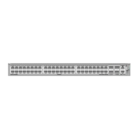
- Page 11 S5590-48S4XC-HI Figure2-7 Front panel (1) SFP port (2) SFP port LED (3) SFP+ port (4) Console port (CONSOLE) (5) Mode button (6) System status LED (SYS) (7) Mode LED (MODE) (8) Expansion card status LED 1 (SLOT1) (9) Expansion card status LED 2 (SLOT2) (10) USB port (11) Management Ethernet port LED (ACT/LINK) (12) Management Ethernet port (MGMT)
-
Page 12: S5590-Ei Switch Series
S5590-EI switch series S5590-28T8XC-EI Figure2-9 Front panel (2) 10/100/1000BASE-T autosensing Ethernet port (1) 10/100/1000BASE-T autosensing Ethernet port (3) SFP port (4) SFP+ port (5) Management Ethernet port (MGMT) (6) Console port (CONSOLE) (7) Mode button (8) USB port (9) System status LED (SYS) (10) Mode LED (MODE) (11) Expansion card status LED (SLOT) (12) Power supply 2 status LED (PWR2) - Page 13 S5590-48T4XC-EI Figure2-11 Front panel (2) 10/100/1000BASE-T autosensing Ethernet port (1) 10/100/1000BASE-T autosensing Ethernet port (3) Management Ethernet port (MGMT) (4) Console port (CONSOLE) (5) Mode button (6) USB port (7) System status LED (SYS) (8) SFP+ port (9) Mode LED (MODE) (10) Expansion card status LED (SLOT) (11) Power supply 2 status LED (PWR2) (12) Power supply 1 status LED (PWR1)
- Page 14 S5590-28S8XC-EI Figure2-13 Front panel (1) SFP port (2) SFP port LED (3) 10/100/1000BASE-T autosensing Ethernet port (4) Management Ethernet port (MGMT) (5) Console port (CONSOLE) (6) Mode button (7) USB port (8) System status LED (SYS) (9) Mode LED (MODE) (10) Expansion card status LED (SLOT) (11) Power supply 2 status LED (PWR2) (12) Power supply 1 status LED (PWR1)
- Page 15 The S5590-28S8XC-EI switch with PID LS-5590-28S8XC-EI-GL supports shipping with fan trays and power supplies installed. For the switch to be shipped with fan trays or power supplies installed, contact the marketing staff. S5590-48S4XC-EI Figure2-15 Front panel (1) SFP port (2) SFP port LED (3) Management Ethernet port (MGMT) (4) Console port (CONSOLE) (5) Mode button...
- Page 16 The S5590-48S4XC-EI switch with PID LS-5590-48S4XC-EI-GL supports shipping with fan trays and power supplies installed. For the switch to be shipped with fan trays or power supplies installed, contact the marketing staff. S5590-28P8XC-EI Figure2-17 Front panel (2) 10/100/1000BASE-T autosensing Ethernet port (1) 10/100/1000BASE-T autosensing Ethernet port (3) SFP port (4) SFP+ port...
- Page 17 The S5590-28P8XC-EI switch came with one expansion slot installed with a filler panel. You can select an expansion card for the switch as required. In Figure2-18, an LSWM2QP2P interface card is installed in the expansion slot. The S5590-28P8XC-EI switch with PID LS-5590-28P8XC-EI-GL supports shipping with fan trays and power supplies installed.
- Page 18 The S5590-48P6XC-EI switch with PID LS-5590-48P6XC-EI-GL supports shipping with fan trays and power supplies installed. For the switch to be shipped with fan trays or power supplies installed, contact the marketing staff.
-
Page 19: Removable Components And Compatibility Matrixes
Removable components and compatibility matrixes The switch supports removable components. Table3-1 describes the removable components available for the switch. Table3-1 Compatibility matrix between switches and removable components S5590-28T8XC- S5590-28T8XC- S5590-48T4XC- S5590-28S8XC- S5590-28P8XC- FRU model S5590-28S8XC- S5590-48S4XC- S5590-48T4XC- S5590-48P6XC- S5590-48S4XC- Removable power supplies PSR250-12A Supported Supported... - Page 20 Table3-2 Expansion card and expansion slot compatibility for the S5590-48T4XC-HI and S5590-48S4XC-HI switches S5590-48T4XC-HI S5590-48S4XC-HI Expansion card Expansion slot 1 Expansion slot 2 mode0 mode1 mode2 mode0 mode1 mode2 LSPM6FWD Supported Supported Supported Supported Supported supported LSWM2EC Supported Supported Supported Supported Supported supported...
-
Page 21: Removable Power Supplies
Rated input voltage range: 100 to 240 VAC @ 50/60 Hz • Max input voltage range: 90 to AC input 290 VAC @ 47 to 63 Hz H3C PSR250-12A & PSR250-12A • Max output power: 250 W PSR250-12A1 Power Modules PSR250-12A1 •... -
Page 22: Removable Fan Trays
See 10GE SFP+ transceiver modules and cables described in Table4-8, Available transceiver modules Table4-9, and Table4-10 and GE SFP transceiver modules and cables and cables described in Table4-6. Reference H3C LSWM2SP8PM & LSWM2SP8P Interface Cards User Manual LSWM2ZQP2P Description 2-port 100GE QSFP28 interface module... - Page 23 Available transceiver modules Table4-9, and Table4-10 and GE SFP transceiver modules and cables and cables described in Table4-6. H3C LSWM2SP2PB & LSWM2SP4PB Interface Cards User Manual Reference LSWM2SP4PB Description 4-port 10GE SFP+ interface module Port type and quantity 4 × 1/10 Gbps SFP+ fiber ports...
-
Page 24: Connecting Cables To The Ports On Expansion Cards
NOTE: To use the LSWM2ZSP8P interface module, make sure the four lowest-numbered or four highest-numbered ports on the module have the same port rate and duplex mode. Connecting cables to the ports on expansion cards To connect cables to the ports on expansion cards, follow these guidelines: •... -
Page 25: Ports And Leds
Ports and LEDs Ports Console port Table4-1 Console port specifications Item Specification Connector type RJ-45 Compliant standard EIA/TIA-232 Port transmission rate 9600 bps (default) to 115200 bps • Provides connection to an ASCII terminal • Services Provides connection to the serial port of a local PC running terminal emulation program Compatible devices All device models... -
Page 26: Sfp Port
All device models NOTE: USB devices from different vendors vary in compatibilities and drivers. H3C does not guarantee correct operation of USB devices from other vendors on the switch. If a USB device fails to operate on the switch, replace it with one from another vendor. - Page 27 IMPORTANT: The SFP-FE-LX-SM1310-BIDI and SFP-FE-LX-SM1550-BIDI transceiver modules must be used in pairs. For example, if one end uses the SFP-FE-LX-SM1310-BIDI transceiver module, the other end must use the SFP-FE-LX-SM1550-BIDI transceiver module. Table4-6 GE SFP transceiver modules and cables available for the SFP+ ports GE SFP Central Cable/Fiber...
- Page 28 • As a best practice, use H3C transceiver modules and network cables for the switch. • The H3C transceiver modules and network cables are subject to change over time. For the most recent list of H3C transceiver modules and cables, contact H3C Support or marketing staff.
- Page 29 Item Specification expansion cards Table4-8 10GE SFP+ transceiver modules available for the SFP+ ports 10GE SFP+ Central Fiber Modal transceiver wavelength Connector diameter bandwidth transmission module (nm) (µm) (MHz × km) distance 2000 300 m (984.25 ft) Multi-mode, 82 m (269.03 ft) 50/125 SFP-XG-SX-M 66 m (216.54 ft)
- Page 30 10GE SFP+ Central Fiber Modal transceiver wavelength Connector diameter bandwidth transmission module (nm) (µm) (MHz × km) distance TX: 1330 SFP-XG-LH40 Single-mode, 40 km (24.86 miles) -SM1330-BIDI 9/125 RX: 1270 TX: 1490 SFP-XG-LH80 Single-mode, 80 km (49.71 miles) -SM1490-BIDI 9/125 RX: 1550 TX: 1550 SFP-XG-LH80...
-
Page 31: Sfp28 Port
• As a best practice, use H3C transceiver modules and network cables for the switch. • The H3C transceiver modules and network cables are subject to change over time. For the most recent list of H3C transceiver modules and cables, contact H3C Support or marketing staff. -
Page 32: Qsfp+ Port
• As a best practice, use H3C transceiver modules and cables for the switch. • The H3C transceiver modules and cables are subject to change over time. For the most recent list of H3C transceiver modules and cables, contact your H3C Support or marketing staff. - Page 33 QSFP+ Central Modal Fiber type and transceiver wavelength Connector bandwidth transmission diameter (µm) module (nm) (MHz × km) distance 2000 100 m (328.08 ft) QSFP-40G-S Multi-mode, R4-MM850 50/125 4700 150 m (492.13 ft) 2000 300 m (984.25 ft) QSFP-40G-C Multi-mode, SR4-MM850 50/125 4700...
-
Page 34: Qsfp28 Ports
• As a best practice, use H3C transceiver modules and cables for the switch. • The H3C transceiver modules and cables are subject to change over time. For the most recent list of H3C transceiver modules and cables, contact your H3C Support or marketing staff. - Page 35 • As a best practice, use H3C transceiver modules and cables for the switch. • The H3C transceiver modules and cables are subject to change over time. For the most recent list of H3C transceiver modules and cables, contact your H3C Support or marketing staff.
-
Page 36: 10/100/1000Base-T Ethernet Port
10/100/1000BASE-T Ethernet port Table4-19 10/100/1000BASE-T Ethernet port specifications Item Specification Connector type RJ-45 • 10 Mbps, half/full duplex • 100 Mbps, half/full duplex Rate, duplex mode, and • auto-MDI/MDI-X 1000 Mbps, full duplex • MDI/MDI-X autosensing Max transmission 100 m (328.08 ft) distance Transmission medium Category 5 or above twisted pair cable... -
Page 37: Mode Led
LED mark Status Description Steady yellow The power supply is present, but it is not operating or is faulty. No power supply is present. Mode LED The mode LED (MODE) works in conjunction with the port status LEDs to show more information about the switch. -
Page 38: Sfp Port Led
Mode LED Ethernet port LED Description (MODE) status status Steady green PoE power supply is normal. • The maximum PoE power provided by the port does not meet the power requirement of the PD. Flashing green • PoE power supply overcurrent, overvoltage, or (PoE mode, Flashing green (1 Hz) short-circuit has occurred. -
Page 39: Expansion Card Status Led
Expansion card status LED The S5590-HI switch series provides two expansion slots at the rear. The S5590-EI switch series provides one expansion slot at the rear. The expansion card status LED on the front panel indicates the operating status of the expansion card. Table4-27 Expansion card status LED description LED mark Status... -
Page 40: Cooling System
Cooling system To dissipate heat timely and enhance system stability, the switch uses a high-performance cooling system. Consider the site ventilation design when you plan the installation site for the switch. The switch uses removable fan trays and provides airflow from the port side to the power supply side or from the power supply side to the port side by using different types of fan trays.
Need help?
Do you have a question about the S5590-HI Series and is the answer not in the manual?
Questions and answers