
Related Manuals for Veria 802


Summary of Contents for Veria 802
- Page 1 VERIA User's guide Videophone entry station Model: VERIA 802 Please readthis manualcarefully before you use it and keep it or a copy thereof in case of further need.
-
Page 2: Table Of Contents
Model: VERIA 232S-W Content 1.Features and main functions 2.Device function and description 2.1. Description of the equipment 2.2. Wiring 3.Contents of the package 4.Wiring diagram 4.1. Diagram of the wiring of the el.lock 4.11. Connection of the el.lock without an additional source 4.12 Connecting the el.lock with an additional source... -
Page 3: Description Of The Equipment
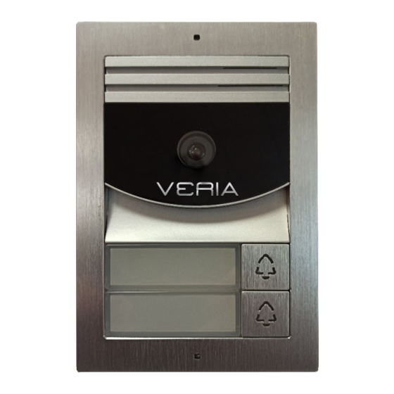
1. Product characteristics and main functions ← 2 wires, easy to connect ← Support for 2 locks ← 1 MPx HD color CMOS camera ← Automatic night light ←Surfaceand drain mounting possible 2. Features and description of the device 2.1. Description of the equipment Speaker Mounting hole for the box Camera optics... -
Page 4: Contents Of The Package
2.2 Description of the wiring (1)Lock control jumper: Set the power mode for the door lock. (2)Password reset button: Press and hold the reset button and restart the door station. The password is successfully reset after two beeps. (3)Multi-user connector (4)Connector for external door control OPEN: Connect the exit button. -
Page 5: Wiring Diagram
Door station Hex wrench Screws Dowle 4. Wiring diagram 4.1 Electrical lock wiring diagram 4.11. Connection of the electric lock without additional power supply. Note: At of up to 5 m of the entrance station and the electric lock, it is not a distance necessary to use an additional power supply of the lock. - Page 6 4.12. Connection of the electric lock with an additional source. Fig.2 Set up Jumpers Power Gate Lock Door Lock (1) Supported door locks: NO (normally open) lock, it is unlocked by switching on. AC/DC5V-24V lock support, ≤ 3A (Instant). (2) Jumper settings: As shown in Figure 2. Set the type and time of unlocking the lock: In the main menu of the 2-wire internal monitor in "Settings", select the option "Device configuration",...
- Page 7 4.2 2-wire bus andodz ozi button (1) Outgoing button: or gate. To select a door or gate Press the exit button to unlock the door lock, go to the "Entry stations list" section of the 2-wire internal monitor to "Outgoing button type". (2) The 2-wire bus does not have polarity.
- Page 8 4.3 Wiring diagram 4.31 Single-pressure input station wiring diagram (A) 1 monitor and 1 entry station (A-1) DC 24V ,1A Adapter Power Supply (A-2) Power supply to DIN rail DC24V, 1A...
- Page 9 (B) 2 monitors and 1 entry station (B-1) DC 24V ,1A Adapter Power Supply (B-2) Power supply to DIN rail DC24V, 1A...
- Page 10 (C) 5 monitors and 1 input station (maximum 5 monitors possible, see Figure 1) (D) 4 monitors and 2 entry stations (see Figure 2) Figure 1 Figure 2 Note: For the specified wiring B and C, the ROOM ADDRESS on all monitors must be set to the same value.
- Page 11 4.32. Diagram of connection of the 2-button entry station The inside of the monitor is set to the room address. (A) DC 24V ,1A Adapter Power Supply (B) Power supply to DIN rail DC24V, 1A Note: (1) 2-wire bus contact settings: The last monitor on the 2-wire bus should have the SW1 switch set to ON.
-
Page 12: Warning
4.The same bus should use the same conductor with the same specification. 1Installation may be carried out by a person who is knowledgeable and properly trained for VERIA systems. NOTE: For security reasons, do not connect the videophone monitor to the power grid before installation is complete. - Page 13 space between the surface and the fixing bracket with silicone sealant outside the bottom for condensate drainage. Videophone wires should not be routed in the same cable as conductors of other installations (bell, alarm, telecommunication systems) or in parallel more than 15 m with another electrical system.
-
Page 14: Assembly
5.3 Assembly (1) Drill 4 holes according to location and insert dowels into the hole. (2) Remove the front panel, insert the label and screw the front panel back on. (3) Fix the mounting box with 4 screws. (4) Connect the cable according to the system connection diagram. (5) Fix the entrance station to the assembly box using the included hex cage (1) Make a hole in the wall according to the size of the mounting box and insert dowels into the hole. - Page 15 Warranty SAFE HOME europe s.r.o. as a supplier, liable to the original buyer that this product will be free from any defects in material and design during normal use and operation for a period of 24months from the sale. The supplier's obligation under this guarantee is limited to date of the replacement of the product.
- Page 16 Havlíčkova 1113/47, 750 02 Přerov Czech Republic Tel.: +420 581 222 262 Website: www.veria.eu SAFE HOME europe, s.r.o. reserves the right to modify and change product specifications without notice. All materials are carefully inspected, but the company SAFE HOME europe, s.r.o.
Need help?
Do you have a question about the 802 and is the answer not in the manual?
Questions and answers