
Related Manuals for GW Instek GLC-10000


Summary of Contents for GW Instek GLC-10000
- Page 1 Leakage Current Tester GLC-10000 USER MANUAL Rev. A ISO-9001 CERTIFIED MANUFACTURER...
- Page 2 This manual contains proprietary information, which is protected by copyright. All rights are reserved. No part of this manual may be photocopied, reproduced or translated to another language without prior written consent of Good Will company. The information in this manual was correct at the time of printing. However, Good Will continues to improve products and reserves the rights to change specification, equipment, and maintenance procedures at any time without notice.
-
Page 3: Table Of Contents
TABLE OF CONTENTS Table of Contents SAFETY INSTRUCTIONS ..........6 OVERVIEW ..............11 Introduction ..........11 Key Features ..........18 Basic Theory ..........22 Leakage Current Modes ......24 Leakage Current Modes ......30 Measurement Flow Chart ......32 Front Panel ..........33 Rear Panel.......... - Page 4 GLC-10000 User Manual External Voltage on a Specific F-type Applied Part Leakage Current (Patient Leakage Current III) ..62 External Voltage on Metal Accesible Part not Protectively Earthed Leakage Current .. 63 Total Patient Leakage Current (Patient Connection – Earth) ............65 Free Current (Enclosure –...
- Page 5 TABLE OF CONTENTS Clock Settings ......... 112 Calibration ..........113 Information ..........114 Measure Settings ........115 REMOTE CONTROL ............117 Remote Interface Configuration ....118 COMMAND OVERVIEW ..........122 Command Syntax ........122 Command List ........125 Appendix for Commands ......185 EXTERNAL I/O ..............
-
Page 6: Safety Instructions
Warning: Identifies conditions or practices that WARNING could result in injury or loss of life. Caution: Identifies conditions or practices that CAUTION could result in damage to the GLC-10000 or to other properties. DANGER High Voltage Attention Refer to the Manual Protective Conductor Terminal... - Page 7 are qualified as service personnel. (Measurement categories) EN 61010-1:2001 specifies the measurement categories and their requirements as follows. the GLC-10000 falls under category II Measurement category IV is for measurement performed at the source of low-voltage installation. ...
- Page 8 Temperature: 0°C to 40°C (Pollution Degree) EN 61010-1:2001 specifies the pollution degrees and their requirements as follows. The GLC-10000 falls under degree 2. Pollution refers to “addition of foreign matter, solid, liquid, or gaseous (ionized gases), that may produce a reduction of dielectric strength or surface resistivity”.
- Page 9 SAFETY INSTRUCTIONS Location: Indoor Storage environment Relative Humidity: < 80% Temperature: −10°C to 50°C Mains supply voltage fluctuations: +/-10 % If the equipment is used in a manner not specified by the manufacturer, the protection provided by the equipment may be impaired.
- Page 10 GLC-10000 User Manual Do NOT replace the detachable MAINS supply Power Cord cord by inadequately RATED cords. Suitable supply cord set shall use with the equipment: - Mains plug: Shall be national approval; - Mains connector: C13 type;...
-
Page 11: Overview
OVERVIEW VERVIEW This chapter describes the GLC-10000 in a nutshell, including the main features, front and rear panel description, and the power up sequence. Introduction Many electrical products must undergo electrical Overview safety testing to ensure their safety. These tests include insulation resistance, withstand voltage, ground continuity and leakage current tests. - Page 12 GLC-10000 User Manual Leakage Current Modes Signal input/ Metal accessible part outputsection (SIP/SOP) notprotectively earthed Refers to the current that flows through a protective Earth Leakage Current grounding wire to earth #1. (General Electrical, Medical Equipment) Refers to the current that flows through a human...
- Page 13 OVERVIEW Refers to the current that flows through an applied Patient part to human body to earth #6. (Medical connection - Earth Leakage Equipment) Current It also refers to the Patient Leakage Current I (Patient Leakage associated with MD-F 1995. Current I) Refers to the current that flows through an applied Enternal Voltage...
- Page 14 GLC-10000 User Manual Measurement Principles Background Leakage current can be categorized into 3 types: Electric current that flows through the body of someone who touches the equipment, the current that flows through a protective grounding wire to earth and the current that flows through a human body connected to an applied part.
- Page 15 OVERVIEW Single Fault conditions include the following: Earth disconnected (excluding earth leakage current tests). Disconnected neutral power line. External equipment failure. (Patient leakage current II, Patient Leakage Current III). Polarity of the power supply can also be switched to measure the leakage current under test. Thus the polarity of the power supply should also be taken into account.
- Page 16 GLC-10000 User Manual UL Standards MD-A MD-B IEC60990-1 MD-C1 MD-C2 MD-C3 IEC60598-1 MD-D Medical MD-F MD-E (without RC filter) Networks IEC61010-1 MD-G MD-H JIS Standards MD-I...
- Page 17 OVERVIEW When conducting leakage current tests, please note Note the following: Under normal operating conditions, leakage current is measured when an electrical device under test is properly insulated with earth. If the device is not properly insulated, the leakage current that is conducted through the measurement network may be invalid.
-
Page 18: Key Features
GLC-10000 User Manual Key Features The GLC-10000 has 12 measurement networks International Standards and (Measuring Devices: MD) supporting GB/12113, Regulations IEC/UL and other international standards for electrical products: 1. MD-A: UL 2. MD-B: UL 3. MD-C1: IEC60990 4. MD-C2: IEC60990 5. - Page 19 OVERVIEW There are a number of leakage current Measurement measurement tests covering general electrical Modes equipment and medical electrical equipment. Earth leakage current Touch current (Enclosure - Earth) Touch current (Enclosure - Enclosure) Touch current (Enclosure - Line) Patient auxiliary current Patient leakage current (Patient connection - Earth) Patient leakage current (external voltage on a...
- Page 20 GLC-10000 User Manual Leakage Current Leakage current measurement modes: Types DC, AC, AC+DC, AC Peak. Automatic/Manual ranges: Measurement Range DC/AC/AC+DC:50uA/500uA/5mA/50mA (Range:4uA~50mA) AC Peak:750uA/7.5mA/75mA (Range:40uA~75mA) Auto/Manual/Programmable Operation Single fault conditions and power supply polarity switch Measurement/Delay time settings Maximum / minimum hold ...
- Page 21 OVERVIEW 30 sets of memory for user defined test Memory conditions 1000 sets of measurements can be saved/recalled Remote Interface There are a variety of remote control interfaces including: RS-232, USB (Host/Device), LAN, EXT I/O connector and GPIB (optional). The LED warning indicator will illuminate and Protection emit a tone by default for:...
-
Page 22: Basic Theory
GLC-10000 User Manual Basic Theory GLC-10000 consists of the following blocks as Overview illustrated in the figure below. Tester and EUT power supply MD (Measuring Device) circuit network Current detection Signal Process CPU/Digital control ... - Page 23 OVERVIEW This switching matrix controls relays to alter the EUT Power EUT power to simulate a number of different test Switching conditions, such as earth open or reverse polarity, etc. Different MD networks represent different MD Network equivalent circuits of a human body. They are chosen according to different regulations.
-
Page 24: Leakage Current Modes
GLC-10000 User Manual Leakage Current Modes As illustrated below, the leakage current generated Definition with a high voltage in an electrical appliance requires measurement under normal EUT (Equipment Under Test) conditions and under single fault conditions. Leakage current can be... - Page 25 OVERVIEW (Touch) Enclosure and Earth Leakage Current Enclosure and Earth Leakage Current During normal conditions, an operator or a patient Description is expected to touch the enclosure of an instrument (except for applied parts). The enclosure and earth leakage current test measures the leakage current that flows through a human body to earth when in contact with the instrument enclosure.
- Page 26 GLC-10000 User Manual (Touch) Enclosure and Enclosure Leakage Current Enclosure and Enclosure Leakage Current Under normal or single fault conditions, the Description leakage current that flows through a human body (operator or patient) from any 2 isolated parts of the enclosure.
- Page 27 OVERVIEW Patient Auxiliary Current Patient Auxiliary Current Patient Auxiliary Current is the leakage current Description that flows through an applied part to human body to applied part. It has nothing to do with type of applied parts or medical equipment class. This measurement is implemented for all medical equipment with multiple applied parts.
- Page 28 GLC-10000 User Manual Enternal Voltage Faulty on a SIP/SOP Signal input/ output section Equipment (SIP/SOP) Leakage Current (Patient Leakage Current II) External Voltage on a SIP/SOP Leakage Current Enternal Voltage on a SIP/SOP Leakage Current Description refers to the current that flows from an applied part through a human body to earth.
- Page 29 OVERVIEW External Voltage on Metal Faulty Accessible Part Metal accessible part Equipment not protectively earthed not Protectively Earthed Leakage Current External Voltage on Metal Accessible Part not Protectively Earthed Leakage Current External Voltage on a Specific F-type Applied Part Description Leakage Current is the leakage current that flows from a malfunctioning applied part, through a person, and through only a F-type applied part.
-
Page 30: Leakage Current Modes
GLC-10000 User Manual Leakage Current Modes Normal Single Type Fault Description Notes Condition Fault 1.Functional grounding wire is disconnected (Class I only) 2.Grounding wire for Earth Leakage 1. Power line patient connection Current disconnected. and power supply circuit for measurement are... - Page 31 OVERVIEW 1 Functional grounding wire is Patient Leakage 1. Power Line disconnected Current (Patient disconnected. 2. Grounding wire for Connection - 2. The protective earth patient connection Earth)/ conductor is discon- and power supply (Patient Leakage nected. circuit for Current I) measurement are disconnected 1.
-
Page 32: Measurement Flow Chart
GLC-10000 User Manual Measurement Flow Chart Reference Page 39, 40 Getting Started Power Up Selecting a meas. network Selecting the safety class Selecting a measuring mode 77 Selecting leak. current type 79 Selecting range Selecting the limits Connect test leads... -
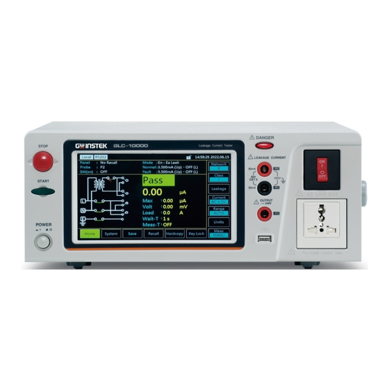
Page 33: Front Panel
OVERVIEW Front Panel DANGER GLC - 10000 Leakage Current Tester STOP LEAKAGE CURRENT 50mA 250V CAT II START 50mA OUTPUT 240V POWER Item Description The power switch turns the power 1. POWER on or off. : ON : OFF The green START button starts 2. - Page 34 GLC-10000 User Manual Measuring Terminals P1 and P2 are 6. Measuring used to measure leakage current. Terminals Terminal P2 has a replaceable fuse (250V, 50mA). The circuit breaker has over-current LC-9000 7. Circuit Leak Current Tester protection for the EUT rated at 20A.
-
Page 35: Rear Panel
OVERVIEW Rear Panel 9 10 13 14 ITEM Description EUT AC inlet. 1. EUT AC AC voltage range: 100V~ Input 240V ±10%, 50/60Hz, 20A Terminal RS-232 interface for remote 2. RS-232 control. Port USB terminal for remote 3. USB control. Port External input/output 4. - Page 36 GLC-10000 User Manual The power socket accepts 6. Power AC mains power for the Socket/ GLC-10000. Fuse socket Power: AC 100V~240V ±10%, 50/60Hz Fuse: T0.63A/250V Supplies AC power for the 7. EUT AC EUT. Output Terminal AC voltage range: 100V~...
- Page 37 OVERVIEW It connects with earth 11. S10 terminal to earthed point of Terminal mesuring supply system. It connects with patient 12. S12 connection to earthed point Terminal of mesuring supply circuit. It connects with earth 13. S13 connection for metal Terminal accesible part not protectively earthed.
-
Page 38: Touch Screen Basics
GLC-10000 User Manual Touch Screen Basics Do not use any sharp objects or excessive pressure on the touch screen display, doing so may damage Caution the display. The LCD touch panel is used to configure system Description and measurement settings. Touching an on-screen icon mimics the action of pressing a button on traditional machines. -
Page 39: Getting Started
GETTING STARTED ETTING STARTED This chapter describes the GLC-10000 in a nutshell, including the main features, front and rear panel descriptions, and the power up sequence. Preparation 22C Ensure the correct fuse is used Fuse before power up. (Fuse: T0.63A/250V) -
Page 40: Power And Probe Connection
GLC-10000 User Manual As the EUT AC Power Output EUT AC Power Socket Socket is designed for multiple regions, it has user-defined live and neutral inputs. To configure the L & N input to your region, see the System>EUT Outlet menu. - Page 41 GETTING STARTED The arrow above shows the EUT AC Input terminal located on the left side of rear panel. If network B (MD B) is selected an isolation Caution transformer that outputs 110% of the rated voltage specified for the EUT is required. The neutral line must be grounded (from the secondary side of the transformer).
- Page 42 GLC-10000 User Manual 1. Ensure the power switch is off on the front EUT AC Output panel. Terminal 2. Connect the AC power wires from EUT to the EUT AC Output terminal on the left side of rear panel. The arrow above shows the EUT AC Output terminal located in the midst of rear panel.
- Page 43 GETTING STARTED To avoid the risk of electric shock, do not touch the tips of the test leads when operating. 1. The foil probe is used to measure the surface Foil Probe leakage current (touch current) of the EUT. Attach the probe metal-foil-side down onto the enclosure of the EUT.
-
Page 44: Tilt The Stand And Hand Carry
GLC-10000 User Manual Tilt the Stand and Hand Carry Place the unit on a flat surface horizontally. Horizontal position Gently pull the 2 stands out from the bottom and Tilt stand position the unit will be placed in the tilt stand position. -
Page 45: Power Up
1. Turn on the power switch. Ensure the EUT Steps power switch is off. 2. The GLC-10000 will load the last panel setting before the last shut down. 3. Wait for the machine to warm up for 30 minutes before operating. -
Page 46: Shut Down
GLC-10000 User Manual Shut Down Before shutdown, ensure the EUT is shut down properly. As illustrated below, power off the circuit breaker before turning off the equipment. EUT Power Down Ensure the circuit breaker is GLC-9000 Leak Current Tester turned off. -
Page 47: Operation
OPERATION PERATION Measurement Terminals When a measurement network is selected, different measuring terminals are required for each test and equipment class. The following tables list which terminals are used for with which network/test. - Page 48 GLC-10000 User Manual Non-medical Network (General Electrical Appliance) MD-A, B, E, H, I CLASS I CLASS II Internal Power Supply Earth Leakage Current - - - (Touch) Enclosure and Earth Leakage Current (Touch) Enclosure and P1, P2 P1, P2 P1, P2...
- Page 49 OPERATION Medical Equipment MD-F CLASS I CLASS II Internal Power Type B Type BF Type CF Type B Type BF Type CF Type B Type BF Type CF Earth Leakage - - - Current (Touch) Normal Enclosure and Earth Leakage Fault P2, P3 P2, P3...
-
Page 50: Earth Leakage Current
GLC-10000 User Manual Earth Leakage Current Non medical network / Medical network Network 1. Connect the EUT power cord to the GLC-10000 Connection as shown in the diagram below. Confirm all settings including MD, leakage current Measurement mode, measurement time, upper and lower limits, Setup and other parameters. -
Page 51: (Touch) Enclosure - Earth Leakage Current51
OPERATION (Touch) Enclosure - Earth Leakage Current Non medical network / Medical network Network As illustrated, ensure that the power source and Connection test leads are properly connected. 1. Connect the test lead to terminal P2. Non-Medical Network 2. Position the test lead on an ungrounded section of the enclosure Non-medical type (General electrical equipment) Medical Network 1. - Page 52 GLC-10000 User Manual Medical type (MD-F) Requires 110% power supply voltage output. The P3 terminal is high voltage. Avoid contact with the terminal. The P3 terminal should not be connected with an earth conductor. Confirm all settings including MD, leakage current...
-
Page 53: (Touch) Enclosure - Enclosure Leakage Current
OPERATION (Touch) Enclosure - Enclosure Leakage Current Non medical network / Medical network Network As illustrated, ensure that the power source and Connection test leads are properly connected. 1. Connect the tests lead to terminals P1& P2. Non-Medical network 2. Position the test leads on un-grounded sections of the enclosure. - Page 54 GLC-10000 User Manual Medical type (MD-F) Requires 110% power supply voltage output. The P3 terminal is high voltage. Avoid contact with the terminal. The P3 terminal should not be connected with an earth conductor. Confirm all settings including MD, leakage current...
-
Page 55: (Touch) Enclosure - Line Leakage Current
OPERATION (Touch) Enclosure - Line Leakage Current Non medical network / Medical network Network As illustrated below, ensure that the power source Connection and test leads are properly connected. 1. Connect the test lead to P2 terminal. Position Non Medical the test lead on an ungrounded section of the Network enclosure. - Page 56 GLC-10000 User Manual 3. Press the START button to start measurements. 4. Press the reset button to stop measurement. Warning Turn the circuit breaker off before removing the EUT. Ensure the power consumption of the EUT doesn’t exceed the rated power limits.
-
Page 57: Patient Auxiliary Current
OPERATION Patient Auxiliary Current Medical network Network As illustrated below, ensure that the power source Connection and test leads are properly connected. Medical Network 1. Connect the test leads to the P1 and P2 terminals. 2. Position the test leads to the applied part of the EUT. -
Page 58: Patient Connection - Earth Leakage Current (Patient Leakage Current I)
GLC-10000 User Manual 5. Press the reset button to stop measurement. Warning Turn the circuit breaker off before removing the EUT. Ensure the power consumption of the EUT doesn’t exceed the rated power limits. Patient Connection - Earth Leakage Current (Patient Leakage Current I) Medical network, (MD-F) for the applied part. - Page 59 OPERATION Medical network (Internal power supply) 1. Position the P2 test lead to the applied part of Class I/Class II the EUT. Medical network (Class I and Class II) Confirm all settings including MD, leakage current Measurement mode, measurement time, upper and lower limits, Setup and other parameters.
-
Page 60: Enternal Voltage On A Sip/Sop Leakage Current (Patient Leakage Current Ii)
GLC-10000 User Manual 3. Press the START button to start measurements. 4. Press the reset button to stop measurement. Warning Turn the circuit breaker off before removing the EUT. Ensure the power consumption of the EUT doesn’t exceed the rated power limits. - Page 61 OPERATION The P3 terminal is high voltage. Avoid contact with the terminal. The P3 terminal should not be connected with an earth conductor. Confirm all settings including MD, leakage current Measurement mode, measurement time, upper and lower limits, Setup and other parameters. 3.
-
Page 62: External Voltage On A Specific F-Type Applied Part Leakage Current (Patient Leakage Current Iii)
GLC-10000 User Manual External Voltage on a Specific F-type Applied Part Leakage Current (Patient Leakage Current III) For medical network circuits only (MD-F), type F Network only. As illustrated, ensure that the power source and Connection test leads are properly connected. -
Page 63: External Voltage On Metal Accesible Part Not Protectively Earthed Leakage Current
OPERATION 3. Press the START button to start measurements. 4. Press the reset button to stop measurement. Warning Turn the circuit breaker off before removing the EUT. Ensure the power consumption of the EUT doesn’t exceed the rated power limits. External Voltage on Metal Accesible Part not Protectively Earthed Leakage Current For medical network circuits only (MD-F), type B... - Page 64 GLC-10000 User Manual The P3 terminal is high voltage. Avoid contact with the terminal. The P3 terminal should not be connected with an earth conductor. Confirm all settings including MD, leakage current Measurement mode, measurement time, upper and lower limits, Setup and other parameters.
-
Page 65: Total Patient Leakage Current (Patient Connection - Earth)
OPERATION Total Patient Leakage Current (Patient Connection – Earth) Medical network, (MD-F) for the applied part. Network Applicable for Class I and Class II types. As illustrated, ensure that the power source and Connection test leads are properly connected. 1. Connect the test lead to the P2 terminal and Class I/Class II position the test lead to the jig for measuring leakage current. -
Page 66: Free Current (Enclosure - Enclosure)
Ensure the power consumption of the EUT doesn’t exceed the rated power limits. It is required to prepare a jig specific for the applied parts of EUT since GLC-10000 is Not able to measure leakage current for all applied parts. Free Current (Enclosure – Enclosure) - Page 67 OPERATION 3. Turn on the circuit breaker. GLC-9000 Panel Operation Leak Current Tester Connect the EUT to the power socket. 4. Press the START button to start measurements. 5. Press the reset button to stop measurement. Warning Turn the circuit breaker off before removing the EUT. Ensure the power consumption of the EUT doesn’t exceed the rated power limits.
-
Page 68: Interface Of Home Screen
GLC-10000 User Manual EASUREMENT Interface of Home Screen Remote Control USB Disk EXT I/O Lock Status Time Panel Setting Test Status Power Operation State Keys Test Info Operation Keys Main Display Shows the currently loaded panel setting. It Panel Panel appears “No Recall”... - Page 69 MEASUREMENT It shows the selected Leakage mode as follows: Mode Earth Leak: Earth leakage current TC (En – Ea): Touch current (Enclosure – Earth) En – Ea Leak: Enclosure - Earth leakage current TC (En – En): Touch current (Enclosure – ...
- Page 70 Status Occurs for specific time in accordance with the set Wait Wait Time. See page 83 for details. Occurs when the GLC-10000 is powered up or Ready when the measurement network, class or leakage current mode is chosen. Press the Start button while in Ready status to enter Test Test mode.
- Page 71 An error occurs from remote control. Remote control mode is underway. EXT I/O It indicates the EXT input/output is connected. Time Displays the current system date and time. Indicates that a USB disk is properly connected with the GLC-10000. Disk...
- Page 72 GLC-10000 User Manual Operation Keys Measuring Network type. Equipment Class type. The selected Network The selected Class appears on the button. appears on the button. Leakage current mode Leakage current type selection. selection. Leakage current range Set leakage current selection.
-
Page 73: Selecting A Measuring Network
MEASUREMENT Selecting a Measuring Network 1. Press the Network button. The Operation twelve network choices will appear accordingly. 2. Press the Right & Left arrow keys to flip through pages of networks choices. 3. To choose a measuring network, press one of the network keys. - Page 74 GLC-10000 User Manual The V1/V2/V3 selections are reflected on the Note Network as shown below in figure A and figure B. Figure A. Figure B. Network F If Network F is selected, a Filter key can be toggled ON or OFF for varied appliacations.
- Page 75 MEASUREMENT Figure A. Figure B. Network EXT If Network EXT is selected, the Resistance value is configurable by pressing + or - keys Range 5000 Ω ~ Ω...
-
Page 76: Selecting The Safety Class/ Grounding Class
GLC-10000 User Manual Selecting the Safety Class/ Grounding Class 1. Press the Class button. The Operation main three options of Earth Class will appear accordingly. 2. To select a class, press one of the class keys. Non Medical Earth Class... -
Page 77: Selecting A Leakage Measurement Mode
MEASUREMENT Selecting a Leakage Measurement Mode 1. Press the Leakage button to Operation enter the leakage section. 2. To choose a measurement mode, press one of the Leakage mode keys. Non Medical Earth leakage current General Touch current (Enclosure – Earth) ... - Page 78 GLC-10000 User Manual Medical MD-F Earth leakage current General Touch current (Enclosure – Earth) Touch current (Enclosure – Enclosure) Touch current (Enclosure – Line) Free current Enclosure – Earth leakage current Enclosure – Enclosure leakage current ...
-
Page 79: Selecting Measurement Parameters
MEASUREMENT Selecting Measurement Parameters Before measurement parameters can be set, the network model, grounding class and measurement mode need to be configured. Setting Leakage Current Type 1. To set the leakage current Operation type, press the Current button. 2. To choose a current type, press one of the current keys. - Page 80 GLC-10000 User Manual Setting the Range 1. To set the range, press the Operation Range button. 2. To set the range to automatic, Auto press key. 3. To set a specified range, press one of the range keys. Range DC, AC, 50.00 mA, 5.00 mA,...
- Page 81 MEASUREMENT MD A,C1,C2,C3,D,E,F,G,I AC, DC, Range 50.00mA 5.000mA 500.0uA 50.00uA AC+DC Maximum 50.00mA 5.000mA 500.0uA 50.00uA Minimum 4.00mA 0.400mA 40.00uA 4.00uA AC Peak Range 75.0mA 7.500mA 750.0uA Maximum 75.0mA 7.500mA 750.0uA Minimum 5.0mA 0.500mA 50.0uA MD B AC, DC, Range 50.00mA 5.000mA 500.0uA...
- Page 82 GLC-10000 User Manual Setting the Limits 1. To set the Upper and Lower Operation limits for both Normal and Fault conditions, press the Limit button to enter the specific setting page. 2. To choose a limit, press one of the limit keys.
- Page 83 MEASUREMENT Auto/Manual Measurement Functions The Meas button is used to configure either manual Background or automatic measurements. 1. To set measurement Operation functions, press the Meas measurement key. 2. Choose MANU mode.
- Page 84 GLC-10000 User Manual 3. Choose a Polarity. MANU Mode Option Non-Medical Normal, Reverse Medical Normal, Reverse 4. Choose a P3-Out. Option Medical (MD-F) 110%N*, 110%R*, 110%OFF Other 5. Choose a line Status. Option Normal, N-OPEN, E-OPEN Non-Medical Live, Neutral (Enclosure – Line)
- Page 85 MEASUREMENT Option Medical S10, S12, S13, S14, S15 The SW terminals are available for MD-F Note medical applications only. The SW terminals can be multiple turned ON simultaneously. Refer to page 37 for details. AUTO Mode 7. Choose AUTO mode. 8.
- Page 86 GLC-10000 User Manual Wait Time 9. Choose 10. Use the keypad below to set the delay time before test. Take 3 minutes for example as follows: 3 minutes Press the C key from keypad to redo value input. Note MeasTime 11.
-
Page 87: Saving Measurement Results
MEASUREMENT Saving Measurement Results When a measurement has completed, all results Background will be displayed on the screen, as shown below. There are a scores of options as the following. Down Operation 1. Use the arrow keys to scroll through the results. Detail 2. - Page 88 GLC-10000 User Manual 4. Press Name to the page where name of the test result can be defined by user. 5. Use the alphanumeric keyboard to enter a file name. Take “TEST” file name for example as follows: TEST Backspace...
-
Page 89: Save/Recall Features
SAVE/RECALL FEATURES AVE/RECALL FEATURES Save Panel Settings The GLC-10000 can save panel settings into Background internal memory. The Panel settings save the following information: Measuring network Class Leakage measurement mode Upper and Lower limits of Normal and Fault ... - Page 90 GLC-10000 User Manual 2. Use the Up and Down arrows to scroll through pages of panel setting files. 3. Choose a file to bring up the save file options. 4. To create or rename the file, press Name key.
- Page 91 SAVE/RECALL FEATURES 5. Use the alphanumeric keyboard to enter a file name. Take “TRIAL” file name for example as follows: TRIAL Backspace Clear all input 6. Press Save key to save the panel setting. 7. Press Return key to return to the previous page.
-
Page 92: Recall Panel Settings Or Test Data
GLC-10000 User Manual Recall Panel Settings or Test Data The Recall menu is divided into 2 parts: Background Panel Settings and Data of Test Results. Recall Panel will recall panel settings, whilst Recall Data will recall results data of measurement. - Page 93 SAVE/RECALL FEATURES 2. Use the Up and Down arrow Recall Panel keys to scroll through each Setting page of saved files. 3. To recall a panel setting, choose a file to recall. The panel setting of selected saved file will be displayed on the screen accordingly.
- Page 94 GLC-10000 User Manual 5. Press DEL key to delete the setting and return to the previous screen. 6. Press Return to return to the previous page directly. 7. To recall data, press the See Data Recall Test Data key from the Recall section.
- Page 95 SAVE/RECALL FEATURES 9. Use the Up and Down arrow keys in the right side to navigate through pages of each data. 10. Press Detail to enter the page of selected data where detailed info of test panel setting are listed for reference.
-
Page 96: Usb Storage
Connection and Navigation The USB port is used to copy files (panel settings, Background measurement results, screen images) and for performing firmware updates. The GLC-10000 recognizes*.CSV *.BMP and *.BIN File Format file formats. Only 8.3 length filenames are supported. File name 1. -
Page 97: Download And Upload Files
Download and Upload Files Panel settings and test data can be copied to USB Background storage, whereas only panel settings can be uploaded from USB storage to GLC-10000. Panel settings have the format *.CSV 1. Press Download key of either Download files... -
Page 98: Firmware Update
GLC-10000 User Manual Firmware Update The firmware update for GLC-10000 series requires an USB 2.0 flash disk and the corresponding “image.BIN” file beforehand. The firmware file “LC1XR.bin”, which is in Note different filename by default, needs to be manually renamed by user for firmware update. For instance, rename the original “GLC_10000_V1.02_... -
Page 99: Save A Screen Image
USB Storage Save a Screen Image Screenshots of display can be captured via the Background Hardcopy button. Each screenshot is saved as a bitmap (*.BMP) file in a directory GLC10000\PICTURE. 1. Insert a USB flash drive into Operation the USB port located on the front panel. -
Page 100: System Settings
GLC-10000 User Manual YSTEM SETTINGS The System key is used to access the System Background section, which can then be used to access a number of different system menus. 1. To access the System section, Panel Operation press the System button. -
Page 101: Meter Measurement
SYSTEM SETTINGS Meter Measurement The Meter section can measure different types of Background voltages: AC, DC,AC+DC and AC peak. Also, the PCC (Protective Conductor Current) current can be measured from this section. 1. From the System section, VOLT Meter press the Meter key followed Mode by VOLT key to display VOLT meter section. - Page 102 GLC-10000 User Manual 3. The instant measured volt will be shown below. The PCC (Protective Conductor Current) PCC Meter Mode measures the current, in the midst of normal conditions, flows through the protective earth conductor, that is, grounding wire. It is not applicable to the Class II equipment, which has no protective earth wire.
- Page 103 SYSTEM SETTINGS 2. Choose a measurement Type and Range. Press the START button to begin measuring. And press the STOP button to stop measuring. Type AC, DC, AC+DC, AC Peak Range 10mA, 75mA 3. The instant measured current will be shown below.
-
Page 104: Eut Voltage And Current Check
GLC-10000 User Manual EUT Voltage and Current Check The EUT voltage and current check tests voltage, Background current and power consumption. Also, the Outlet setting for output terminals to EUT can be set up from this section. 1. From the System section,... - Page 105 SYSTEM SETTINGS The EUT Outlet menu will allow you to select the live and neutral terminals polarity on AC blocks of front and rear panels, individually. 2. First select the Front or Rear output terminal followed by setting up which terminal polarity will be employed.
-
Page 106: Initialize Menu
GLC-10000 User Manual Initialize Menu The Initialize section allows user to initialize a Background number of settings. Saved test data and panel settings can be deleted. The System and Factory default settings can be performed to restore. 1. From the System section,... -
Page 107: System Self Test
SYSTEM SETTINGS System Self Test The Self Test function allows the system functions Background to be checked automatically. 1. From the System section, Panel Operation press the Self Test key to enter the specific section. 2. To perform a self test, choose any of the soft test functions (RAM, LCD, LED, Buzzer). -
Page 108: Beep Settings
GLC-10000 User Manual Beep Settings The Beep section is used to set tones for a scrores Background of different events. 1. From the System section, Panel Operation press the Beep key to enter the specific section. Setting an event to ON will allow a tone to be heard when that event occurs. -
Page 109: Display Settings
SYSTEM SETTINGS Display Settings The Display section adjusts the LCD Light and the Background Language for user interface. 1. From the System section, Panel Operation press the Display key to enter the specific section. 2. Press the + or – keys to increase Back Light or decrease the light intensity. -
Page 110: Interface Settings
GLC-10000 User Manual Interface Settings The Interface section is used to select the remote Background control interface with affiliated settings. After a connection has been established, an interface icon will be shown in the upper-left corner of display. 1. From the System section,... - Page 111 SYSTEM SETTINGS 6. First select DHCP (Dynamic Host Configuration Protocol) ON or OFF. When choosing ON, IP address along with affiliated parameters will be automatically assigned. Option ON, OFF 7. If DHCP is selected OFF, manually set the following parameters in accordance with actual applications.
-
Page 112: Clock Settings
GLC-10000 User Manual Clock Settings The Clock section is used to set time and date. Background 1. From the System section, Panel Operation press the Clock key to enter the specific section. 2. Use the + and – keys to set... -
Page 113: Calibration
SYSTEM SETTINGS Calibration The Calibration section is used to access to the Background calibration function, which requires a password to enter the menu. Please see your distributor or dealer for details when necessary. 1. From the System section, Panel Operation press the right arrow key to next page followed by pressing the Calibration key to... -
Page 114: Information
GLC-10000 User Manual Information Used to check GLC-10000 Firmware version Background number, Serial number as well as MAC info. 1. From the System section, Panel Operation press the right arrow key to next page followed by pressing the Information key to enter the specific section. -
Page 115: Measure Settings
SYSTEM SETTINGS Measure Settings The Measure section refers to configuring on both Background Frequency and BNC settings. 1. From the System section, Panel Operation press the right arrow key to next page followed by pressing the Measure key to enter the specific section. 2. - Page 116 GLC-10000 User Manual When network F(2020) is selected, the frequency range setting of the instrument is 0.1 - 1 MHz, Note which allows user to select either 0.1 Hz - 1 MHz or 15 Hz - 1 MHz. An 0.1 Hz - 1 MHz setting will slow down the response of internal circuits and increase measurement time.
-
Page 117: Remote Control
REMOTE CONTROL EMOTE CONTROL This chapter describes basic configuration of IEEE488.2 based remote control. For a command list, refer to the Command Overview chapter on page 122. Remote Interface Configuration ........118 Configure USB Connection ..............118 Configure RS232 Connection ..............119 Configure GPIB Connection .............. -
Page 118: Remote Interface Configuration
1. Connect the Type A-Type B USB Steps cable from PC side to the rear panel USB B port of GLC-10000. 2. Press the System button to access the System section. 3. Press the Interface key to enter the specific section. -
Page 119: Configure Rs232 Connection
2. Press the System button to access the System section. 3. Press the Interface key to enter the specific section. 4. Press the RS232 key to set the interface to RS232. 5. Select an appropriate Baud Rate of GLC-10000 corresponding to the setting of PC side. -
Page 120: Configure Gpib Connection
3. Press the Interface key to enter the specific section. 4. Press the GPIB key to set the interface to GPIB. 5. Select an appropriate Address of GLC-10000 corresponding to the setting of PC side. 6. Enter the following command to test the system. * IDN? -
Page 121: Configure Lan Connection
* IDN? If remote control is working correctly, the query will return the machine manufacturer, model, serial number and firmware version number. GW INSTEK, GLC-10000, SN: xxxxxxxx, Vx.xx And the RMT icon will appear on the upper-left corner of GLC-10000 display. -
Page 122: Command Overview
GLC-10000 User Manual OMMAND OVERVIEW The Command overview chapter lists all programming commands in functional order as well as alphabetical order. The command syntax section shows you the basic syntax rules you have to apply when using commands. Command Syntax... - Page 123 COMMAND OVERVIEW There are a number of different instrument Command Types commands and queries. A command sends instructions or data to the unit and a query receives data or status information from the unit. Command types A single command Simple with/without a parameter CONFigure:AUTO ON Example...
- Page 124 GLC-10000 User Manual Command SYSTem:BACKlight Format Command header Parameter 1 Space Common Type Description Example Input Parameters <Boolean> boolean logic 0, 1 <NR1> integers 0, 1, 2, 3 <NR2> decimal numbers 0.1, 3.14, 8.5 <NR3> floating point with 4.5e-1, 8.25e+1 exponent <NRf>...
-
Page 125: Command List
COMMAND OVERVIEW Command List Measurement NETWork ..............128 Network Commands Measuring EQUipment ..............129 Equipment EQUipment:TYPE ............129 Configuration Commands Measurement MODE ................131 Mode Commands Measurement CONFigure:AUTO ............133 Commands NETWork:MEDical:YEAR ..........133 NETWork:MEDical:FILTer .......... 134 NETWork:C2FILTer ............. 135 NETWork:C3FILTer ............. - Page 126 GLC-10000 User Manual Measure STARt ................154 Commands STOP ................154 Measurement MEASure? ..............155 Data Commands Save Data MEMory:NUMBer ............157 Commands MEMory:IDENtity ............157 MEMory:MEASure ............158 MEMory:SAVE ............. 160 MEMory:SAVE:AUTO ..........160 System Setup SYSTem:MODE ............161 Commands SYSTem:EUT ...............
- Page 127 COMMAND OVERVIEW Voltage mode CONFigure:VOLTage ..........178 Commands CONFigure:VOLTage:RANGe ........179 MEASure:VOLTage? ............ 180 Protective CONFigure:PCC ............181 conductor current CONFigure:PCC:RANGe ..........182 mode Command MEASure:PCC? ............183 Error Information Error information ............183 Commands...
- Page 128 GLC-10000 User Manual Measurement Network Commands NETWork ..............128 NETWork Query Sets or queries the measurement network. The set command can only be used in leakage current mode. Note Syntax NETWork {A|B|C1|C2|C3|D|E|F|G|H|I|EXT} Query Syntax NETWork? Query Return Returns network type: A|B|C1|C2|C3|D|E|F|G|H|I|EXT...
-
Page 129: Measuring Equipment
COMMAND OVERVIEW Measuring Equipment Configuration Commands EQUipment ..............129 EQUipment:TYPE ............129 EQUipment Query Sets or queries the EUT class. The set command can only be used in leakage current mode. Note Syntax EQUipment {CLAss1|CLAss2|INTernal} Query Syntax EQUipment? Query Return Returns the equipment class of the EUT as a string: CLASS1|CLASS2|INTERNAL Example EQUipment CLAss1... - Page 130 GLC-10000 User Manual Example EQUipment:TYPE BF The applied part of the EUT is set to type BF for network F. Query Example EQUipment:TYPE? Return: BF Type BF is the currently applied part of the EUT for network F.
-
Page 131: Measurement Mode
COMMAND OVERVIEW Measurement Mode Commands MODE ................131 MODE Query Set or queries the measurement mode of leakage current. Different measuring networks have different Note measurement modes. Refer to the Appendix 1 on page 185 for details. The set command can only be used in leakage current mode. - Page 132 GLC-10000 User Manual Example MODE EARTH Sets the measurement mode to Earth leakage current. Query Example MODE? Return: EARTH Earth leakage current is the current measurement mode.
-
Page 133: Measurement Configure:auto
COMMAND OVERVIEW Measurement Commands CONFigure:AUTO .............133 NETWork:MEDical:YEAR ...........133 NETWork:MEDical:FILTer .........134 NETWork:C2FILTer ............135 NETWork:C3FILTer ............136 CONFigure:AUTO Query Configures or queries the measurement funciton of leakage current. The set command can only be used in leakage current mode. Note Syntax CONFigure:AUTO {ON|OFF} Query Syntax CONFigure:AUTO? Query Return... -
Page 134: Network:medical:filter
GLC-10000 User Manual This command can only be used with network F. Note The set command can only be used in leakage current mode. Syntax NETWork:MEDical: YEAR {“2020”|”1995”} NETWork:MEDical: YEAR? Query Syntax Query Return Returns a string indicating Network F applicable standard year. -
Page 135: Network:c2Filter
COMMAND OVERVIEW Query Example NETWork:MEDical:FILTer ? Return: OFF Returns the RC filter status. The RC filter is turned off. NETWork:C2FILTer Query Sets or queries whether Network C2 has the RC network enabled/disabled. This command can only be used with network C2. Note The set command can only be used in leakage ... -
Page 136: Network:c3Filter
GLC-10000 User Manual NETWork:C3FILTer Query Sets or queries whether Network C3 has the RC network enabled/disabled. This command can only be used with network C3. Note The set command can only be used in leakage current mode. Syntax... -
Page 137: Measurement Configure:comparator
COMMAND OVERVIEW Measurement Items Commands CONFigure:COMParator ...........137 CONFigure:COMParator:SWITch ......138 CONFigure:COMParator:FAULt .......139 CONFigure:COMParator:FAULt:SWITch ....140 CONFigure:CURRent ..........141 CONFigure:RANGe ...........142 CONFigure:SWITch ...........143 CONFigure:COMParator Query Sets or queries the current measuring mode’s upper and lower limit of leakage current. The set command can only be used in leakage current mode. Note Syntax CONFigure:COMParator {NR3,NR3}... -
Page 138: Items Commands Configure:comparator:switch
GLC-10000 User Manual CONFigure:COMParator:SWITch Query Sets or queries the current measuring mode’s upper and lower limit of leakage current which has the switch enabled/disabled. The set command can only be used in leakage current mode. Note Syntax CONFigure:COMParator:SWITch { str,str}... -
Page 139: Configure:comparator:fault
COMMAND OVERVIEW CONFigure:COMParator:FAULt Query Sets or queries the current measuring mode’s upper and lower limit of leakage current in single fault condition. The set command can only be used in leakage current mode. Note Syntax CONFigure:COMParator:FAULt {NR3,NR3} Query Syntax CONFigure:COMParator:FAULt? Query Return Returns the current measuring mode upper and lower limit in single fault condition. -
Page 140: Configure:comparator:fault:switch
GLC-10000 User Manual CONFigure:COMParator:FAULt:SWITch Query Sets or queries the current measuring mode’s upper and lower limit of leakage current in single fault condition which has the switch enabled/disabled. The set command can only be used in leakage current mode. Note... -
Page 141: Configure:current
COMMAND OVERVIEW CONFigure:CURRent Query Sets or queries the current type of leakage current. When the following configurations, which include the Note network F, the applicable standard year 2020 and the measure frequency 0.1Hz, are set, AC peak can’t be set. Some times can’t be set some one. -
Page 142: Configure:range
GLC-10000 User Manual CONFigure:RANGe Query Sets or queries the current range of leakage current. When the following configurations, which include the Note network F, the applicable standard year 2020 and the measure frequency 0.1Hz, are set, AUTO Range can’t be set. -
Page 143: Configure:switch
COMMAND OVERVIEW Query Example CONFigure:RANGe? Return: AUTO the leakage current range is AUTO. CONFigure:SWITch Query Sets or queries each Medical Ground switch state. Some times can’t be set for some one. Refer to the Note Appendix 4 on page 198 for details. The set command can only be used in leakage ... -
Page 144: Manual Configure:condition
GLC-10000 User Manual Manual Measurement Commands CONFigure:CONDition ..........144 CONFigure:APPLy ............. 145 CONFigure:POLarity ..........146 CONFigure:WTIMe ........... 147 CONFigure:CONDition Query Sets or queries the EUT status when in manual testing. Some times can’t be set for some one. Refer to the Note Appendix 2 on page 188 for details. -
Page 145: Measurement Configure:apply
COMMAND OVERVIEW Query Example CONFigure:CONDition ? Return: NORMAL The leakage current test is normal conditions. CONFigure:APPLy Query Sets or queries the 110% power status when in manual testing. Some times can’t be set for some one. Refer to the Note Appendix 2 on page 188 for details. -
Page 146: Commands Configure:polarity
GLC-10000 User Manual CONFigure:POLarity Query Sets or queries the power supply polarity in manual testing. This command can’t be set when EUT class is Note internally powered or when measurement mode of leakage current is Enclosure – Line. The set command can only be used in leakage ... -
Page 147: Configure:wtime
COMMAND OVERVIEW CONFigure:WTIMe Query Sets or queries the wait time in manual function. Range: 1~999 seconds. The set command can only be used in leakage Note current mode. The command can only be used in manual measurement funciton. Syntax CONFigure:WTIMe <NR1>... -
Page 148: Amc
GLC-10000 User Manual Automatic Measurement Commands AMC ................148 CONFigure:AMITem:CONDition......148 CONFigure:AMITem:APPLy ........150 CONFigure:AMITem:POLarity ........151 CONFigure:AMTime ..........152 CONFigure:AMTime:WAI ......... 153 Query Queries the automatic measurement completion. The set command can only be used in leakage current mode. - Page 149 COMMAND OVERVIEW The set command can only be used in leakage Note current mode. The command can only be used in Automatic function. Syntax CONFigure:AMITem:CONDition {NR1,NR1} Query Syntax CONFigure:AMITem:CONDition? Query Return First vaule : <NR1> Returns a 3-bit integer (0~7). Second vaule : <NR1>...
-
Page 150: Commands Configure:amitem:apply
GLC-10000 User Manual Query Example CONFigure: AMITem:CONDition? Return: 3,0 normal power supply and Power source disconnected is The EUT status of auto measurement settings. CONFigure:AMITem:APPLy Query Configures or queries the 110% power status of auto measurement settings. The settings must be compatible with the measuring network, class and leakage mode. -
Page 151: Configure:amitem:polarity
COMMAND OVERVIEW Query Example CONFigure: AMITem:APPLy? Return: 3 positive phase and Negative phase is The 110% power of auto measurement settings. CONFigure:AMITem:POLarity Query Configures or queries the power supply polarity of auto measurement settings. The command can only be used in Automatic Note function. -
Page 152: Configure:amtime
GLC-10000 User Manual CONFigure:AMTime Query Sets or queries the auto measurement duration, ranging from 2~999 seconds. The command can only be used in Automatic Note function. The set command can only be used in Leakage current mode. Syntax CONFigure:AMTime <NR1>... -
Page 153: Configure:amtime:wai
COMMAND OVERVIEW CONFigure:AMTime:WAI Query Sets or queries the wait time in automatic mode. Range: 1~999 seconds. The command can only be used in Automatic Note function. The set command can only be used in Leakage current mode. Syntax CONFigure:AMTime:WAI <NR1>... -
Page 154: Start
GLC-10000 User Manual Measure Commands STARt ................. 154 STOP ................154 STARt Starts the measurement. Syntax STARt Example STARt Starts the measurement. STOP Stops the measurement. Syntax STOP Example STOP Stops the measurement. -
Page 155: Measurement Measure
COMMAND OVERVIEW Measurement Data Commands MEASure? ..............155 MEASure? Query Queries the measurement value. The command can only be used in Leakage current mode. Note Query Syntax MEASure? Query Return Returns the 4 values and 5 strings. <value1> The test number: Always 1 in manual function. - Page 156 GLC-10000 User Manual < string 3> Equipment status: NORMAL /E_OPEN /N_OPEN LIVE / NEUTRAL NORMAL: Normal conditions N_OPEN: Disconnected live line. E_OPEN: Disconnected earth line. LIVE: Normal live line connection conditions. Application of voltage from the live line. NEUTRAL: Normal neutral line connection conditions.
-
Page 157: Save Data Memory:number
COMMAND OVERVIEW Save Data Commands MEMory:NUMBer ............. 157 MEMory:IDENtity ............. 157 MEMory:MEASure ............ 158 MEMory:SAVE ............160 MEMory:SAVE:AUTO ..........160 MEMory:NUMBer Query Queries the data where the file no. is recorded and saved. The command can only be used in Leakage current mode. Note Query Syntax MEMory:NUMBer? -
Page 158: Memory:measure
GLC-10000 User Manual Query Example MEMory:IDENtity? 6 Return: CeL,NO-6, 2018/08/08 08:08:08. Where CeL is the name of the file. 6 is the file number and 2018/08/08 08:08:08 is the update time. MEMory:MEASure Query Queries the measurement values. The command can only be used in Leakage current mode. - Page 159 COMMAND OVERVIEW REVERSE: Negative polarity < string 3> Equipment status: NORMAL /E_OPEN /N_OPEN LIVE / NEUTRAL NORMAL: Normal conditions N_OPEN: Disconnected live line. E_OPEN: Disconnected earth line. LIVE: Normal live line connection conditions. Application of voltage from the live line. NEUTRAL:Normal neutral line connection conditions.
-
Page 160: Memory:save
GLC-10000 User Manual Query Example MEASure:AUTO?6 +1.031E-03,+1.001E-03, PASS, NORMAL, NORMAL,-- ------,AC + DC, +1.024E-03,+1.003E-03, PASS, NORMAL, N_OPEN,--- -----,AC + DC, +1.040E-03,+1.010E-03, PASS,REVERSE, NORMAL,---- ----,AC + DC, +1.019E-03,+0.999E-03, PASS,REVERSE, N_OPEN,----- ---,AC + DC, MEMory:SAVE Manual saves measurement results, including file name, file no.,... -
Page 161: System Setup System:mode
COMMAND OVERVIEW System Setup Commands SYSTem:MODE ............161 SYSTem:EUT ..............162 SYSTem:FREQuency ..........162 SYSTem:BACKlight ............163 SYSTem:BEEPer:VOL ..........163 SYSTem:BEEPer:COMParator ........164 SYSTem:BEEPer:KEY ..........165 SYSTem:BEEPer:T3OUT ..........166 SYSTem:FILE:NAME ..........167 SYSTem:DATA:NAME ..........167 SYSTem:CLEar:MEASure ...........168 SYSTem:CLEar:PANel ..........168 SYSTem:DATE ............169 SYSTem:TIME ............169 SYSTem:FILE .............170 SYSTem:LOAD ............174 SYSTem:SAVE ............174 SYSTem:TEST:VA ............174 SYSTem:MODE Query Sets or queries the meter mode. -
Page 162: Commands System:eut
GLC-10000 User Manual Query Example SYSTem:MODE ? Return: LC The meter mode is Leakage current meter SYSTem:EUT Query Sets or queries the output terminal and polarity of EUT power. The set command can only be used in Leakage current mode. -
Page 163: System:backlight
COMMAND OVERVIEW 0.1Hz: measurement frequency lower than 15Hz Example SYSTem:frequency “15Hz” Sets the measurement frequency level is 15Hz. Query Example SYSTem: frequency? Return: 15Hz The measurement frequency higher than 15Hz. SYSTem:BACKlight Query Sets or queries the brightness level of the LCD display. The set command can only be used in Leakage current mode. -
Page 164: System:beeper:comparator
GLC-10000 User Manual Query Syntax SYSTem:BEEPer:VOL? Query Return Returns the buzzer volume. 1:lowest ; 3:highest Example SYSTem:BEEPer:VOL 2 Sets the buzzer volume is 2. Query Example SYSTem:BEEPer:VOL? Return: 2 The buzzer volume is 2. SYSTem:BEEPer:COMParator Query Sets or queries the alarm tone for judgment events. -
Page 165: System:beeper:key
COMMAND OVERVIEW SYSTem:BEEPer:KEY Query Sets or queries whether a tone is set for key entry (button presses). The set command can only be used in Leakage current mode. Note Syntax SYSTem:BEEPer:KEY {ON|OFF} Query Syntax SYSTem:BEEPer:KEY? Query Return Returns a string to indicate if a tone will sound when a key is pressed. -
Page 166: System:beeper:t3Out
GLC-10000 User Manual SYSTem:BEEPer:T3OUT Query Sets or queries the tone sound of the P3 output when the voltage output is at 110%. The set command can only be used in Leakage current mode. Note Syntax SYSTem:BEEPer:T3OUT {ON|OFF} Query Syntax SYSTem:BEEPer:T3OUT? -
Page 167: System:file:name
COMMAND OVERVIEW SYSTem:FILE:NAME Query Sets or queries the panel name for save. Only alphanumeric characters (A-Z, a-z, 0-9) and the Note “_” underscore character can be used. The set command can only be used in Leakage current mode. Syntax SYSTem:FILE:NAME <”string”>... -
Page 168: System:clear:measure
GLC-10000 User Manual SYSTem:CLEar:MEASure Query Clears all the saved measurement data. All the saved values will be deleted after this Note command is executed. The set command can only be used in Leakage current mode. Syntax SYSTem:CLEar:MEASure {ALL}... -
Page 169: System:date
COMMAND OVERVIEW SYSTem:DATE Query Sets or queries the system date. Syntax SYSTem:DATE <Year>,<Month>,<Day> Query Syntax SYSTem:DATE? Query Return Returns the system date:<Year>,<Month>,<Day>. Year 2000~2099(<NR1>) Month 1~12(<NR1>) 1~31(<NR1>) Example SYSTem:DATE 2018,11,26 Sets the system date to November 26, 2018 Query Example SYSTem:DATE? 2018,11,26 Returns the year, month and day. -
Page 170: System:file
GLC-10000 User Manual Query Example SYSTem:TIME? Return: 15:30:27 (System time is 15:30:27). SYSTem:FILE Query Queries all the contents of a panel settings. The set command can only be used in Leakage current mode. Note Query Syntax SYSTem:FILE? <NR1> <NR1> File number, ranging from 1~30. - Page 171 COMMAND OVERVIEW |PATIENTP2E|PATIENTSIPSOP |PATIENTFTYPE|PATIENTMP |TPATIENTP2E|TPATIENTSIPSOP |TPATIENTFTYPE|TPATIENTMP|FR < string9> Measurement method: AUTO / MANU < string10> Leakage current type: AC /DC /AC+DC /ACPEAK < string11> Measurement range: AUTO|HOLD1|HOLD2|HOLD3|HO When the leakage current type is AC, DC or AC+DC: HOLD1: 50.00uA range HOLD2: 500.0uA range HOLD3: 5.000mA range HOLD4: 50.00mA range...
- Page 172 GLC-10000 User Manual <Num value5> Medical Ground switch (NR1) bit7 bit6 bit5 bit4 bit3 bit2 bit1 bit0 SW15 SW14 SW13 SW12 SW10 <Num value6> Power supply polarity item: (NR1) bit0 : positive phase bit1 : negative phase <Num value7> EUT status item:...
- Page 173 COMMAND OVERVIEW Query Example SYSTem:FILE? 1 Return: NO.01,PANEL 01 CLASS1,--,D,--,15Hz,TOUCH1,MANU,AC + DC,AUTO,3.500E-03,OFF,5.500E-03,OFF,0,1,1,0 ,1s,OFF The 1th file has the following configuration: File No. NO.01 File name PANEL 01 Equipment class CLASS-I Application type of Medical network -- Network Network filter Measurement frequency 15Hz Measurement mode Touch Enclosure -...
-
Page 174: System:load
GLC-10000 User Manual EUT status item Normal 110% voltage application item NONE Measurement wait time Measurement measuring time SYSTem:LOAD Query Loads panel settings from memory. The set command can only be used in Leakage current mode. Note Syntax SYSTem:LOAD <NR1>... - Page 175 COMMAND OVERVIEW <num value1> The voltage between the live and neutral lines (NR3).(unit : V) <num value2> The load current (NR3). (unit : A) <num value3> The VA value (voltage X current)(NR3). (unit : VA) <num value4> The voltage between the live and earth lines(NR3).
-
Page 176: System Related System:error
GLC-10000 User Manual System Related Commands SYSTem:ERRor ............176 *IDN? ................. 176 *CLS ................177 SYSTem:ERRor Query Reads error information of the previous error. See the error information table. Query Syntax SYSTem:ERRor? Query Return Returns an error string that includes an error code and an error description. -
Page 177: Cls
COMMAND OVERVIEW *CLS Query Clears the internal registers and error message, if any. Syntax *CLS RS232 Interface Commands SYSTem:LOCal ............. 177 SYSTem:LOCal Query Sets the machine to local mode. Syntax SYSTem:LOCal... - Page 178 GLC-10000 User Manual Voltage mode Commands CONFigure:VOLTage ..........178 CONFigure:VOLTage:RANGe ........179 MEASure:VOLTage? ..........180 CONFigure:VOLTage Query Sets and queries the target voltage When measure frequency is 0.1Hz, the target voltage Note ACpeak can’t be set. The set command can only be used in voltage mode.
- Page 179 COMMAND OVERVIEW CONFigure:VOLTage:RANGe Query Sets or queries the voltage range. AUTO Range can’t be set when measure frequency is Note 0.1Hz. HOLD4 Range can’t be set when target voltage is ACpeak. The set command can only be used in voltage mode. ...
- Page 180 GLC-10000 User Manual Query Example CONFigure: VOLTage:RANGe? Return: AUTO the voltage range is AUTO. MEASure:VOLTage? Query Queries the measurement value. The set command can only be used in voltage mode. Note Query Syntax MEASure:VOLTage? Query Return Returns the value. <value> (NR3)
- Page 181 COMMAND OVERVIEW Protective conductor current mode Commands CONFigure:PCC ............181 CONFigure:PCC:RANGe ...........182 MEASure:PCC? ............183 CONFigure:PCC Query Sets or queries the protective conductor current type. The command can only be used in protective Note conductor current mode. Syntax CONFigure:PCC {ACDC|AC|DC|ACPeak} Query Syntax CONFigure: PCC? Query Return Returns the protective conductor current type as a...
- Page 182 GLC-10000 User Manual CONFigure:PCC:RANGe Query Sets or queries the protective conductor current range. The command can only be used in protective Note conductor current mode. Syntax CONFigure:PCC:RANGe{HOLD1|HOLD2} Query Syntax CONFigure:PCC:RANGe? Query Return Returns the protective conductor current range as a...
- Page 183 COMMAND OVERVIEW MEASure:PCC? Query Queries the measurement value. The command can only be used in protective Note conductor current mode. Query Syntax MEASure:PCC? Query Return Returns the value. <value> (NR3) The now value in Amps Query Example MEASure:PCC? +1.031E-03 Error information Commands Error information ............
- Page 184 GLC-10000 User Manual Not Medical network Leakage Current Set Error Measure Type Set Error Measure Range Set Error Normal Current HI SET Error Normal Current LOW SET Error Fault Current HI SET Error Fault Current LOW SET Error Ground Switch Set Error...
-
Page 185: Appendix For Commands
COMMAND OVERVIEW Appendix for Commands Appendix 1 - Leakage Current Mode Table Under Network A, B, E, H, I ,EXT Machine Status CLASS-I CLASS-II Int Power Measurement Mode ● Earth leakage current ● ● ● Enclosure to earth leakage current ●... - Page 186 GLC-10000 User Manual Under Network F and IEC60601-1 of 1995 Machine Status CLASS-I CLASS-II Int Power Applied Part Measurement Mode Earth leakage current ● ● ● Enclosure to earth ● ● ● ● ● ● ● ● ● leakage current Enclosure to enclosure ●...
- Page 187 COMMAND OVERVIEW Under Network F and IEC60601-1 of 2020 Machine Status CLASS-I CLASS-II Int Power Applied Part Measurement Mode Earth leakage current ● ● ● Touch current – ● ● ● ● ● ● ● ● ● enclosure to earth Touch current –...
- Page 188 GLC-10000 User Manual Appendix 2 – Test Condition Table Under Network A, B, E, H, I ,EXT Machine Status : CLASS-I Condition Live Neutral Power line Earth Normal disconnect disconnect line output line output Measurement Mode ● ● Earth leakage current Enclosure to earth ●...
- Page 189 COMMAND OVERVIEW Machine Status : Int Power Condition Live Neutral Power line Earth Normal disconnect disconnect line output line output Measurement Mode Earth leakage current Enclosure to earth ● leakage current Enclosure to enclosure ● leakage current Enclosure to line leakage current ●...
- Page 190 GLC-10000 User Manual Machine Status : CLASS-II Condition Live Neutral Power line Earth Normal disconnect disconnect line output line output Measurement Mode Earth leakage current Touch current – ● ● enclosure to earth Touch current – ● ● enclosure to enclosure Touch current –...
- Page 191 COMMAND OVERVIEW Enclosure to earth ● ● ● ● ● ● leakage current Enclosure to enclosure ● ● ● ● ● ● leakage current ● ● ● Patient auxiliary current Patient ● ● ● leakage current I Patient ● ● leakage current II Patient ●...
- Page 192 GLC-10000 User Manual Machine Status : Int Power Application of 110% voltage : Condition Power line Earth Normal disconnect disconnect Positive Negative Measurement Mode Earth leakage current Enclosure to earth ● ● ● ● leakage current Enclosure to enclosure ●...
- Page 193 COMMAND OVERVIEW ● ● ● Patient auxiliary current Patient leakage current ● ● ● (Patient connection - Earth) Patient leakage current ● ● ● ● ● (external voltage on SIP/SOP) Patient leakage current (external voltage on ● ● a specific F-type applied part) Patient leakage current (external voltage on...
- Page 194 GLC-10000 User Manual Touch current – ● ● ● ● ● enclosure to enclosure ● ● Patient auxiliary current Patient leakage current ● ● (Patient connection - Earth) Patient leakage current ● ● ● ● (external voltage on SIP/SOP) Patient leakage current (external voltage on ●...
- Page 195 COMMAND OVERVIEW Touch current – ● ● ● ● enclosure to earth Touch current – ● ● ● ● enclosure to enclosure ● Patient auxiliary current Patient leakage current ● (Patient connection - Earth) Patient leakage current ● ● ● (external voltage on SIP/SOP) Patient leakage current...
- Page 196 GLC-10000 User Manual Appendix 3 – Target Current Type Table Under Network A, B, E, H, I ,EXT Network A /B /E /H I /EXT Measurement Mode Earth leakage current Enclosure to earth leakage current AC + DC AC + DC...
- Page 197 COMMAND OVERVIEW Patient leakage current II Patient leakage current III AC + DC Free current AC + DC ACpeak Under Network F and IEC60601-1 of 2020 Network F and IEC60601-1 of 2020 Measurement Mode Earth leakage current Touch current – enclosure to earth AC + DC Touch current –...
- Page 198 GLC-10000 User Manual Appendix 4 – Medical Ground Switch Table Under Network F and IEC60601-1 of 1995 Machine Status CLASS-I CLASS-II Int Power Switch S10 S12 S13 S14 S15 S10 S12 S13 S14 S15 S10 S12 S13 S14 S15 Measurement...
- Page 199 COMMAND OVERVIEW Patient auxiliary current ● ● Patient leakage current ● ● ● ● ● ● (Patient connection - Earth) Patient leakage current ● ● ● ● (external voltage on SIP/SOP) Patient leakage current (external voltage on ● ● ● ●...
-
Page 200: External I/O
GLC-10000 User Manual XTERNAL I/O Features 1. Remote Start/Stop control 2. Recall the last 30 panel settings 3. Output measurement results. 4. Output measurement timing signals 5. Enable internal or external power Cautions 1. To prevent damage, ensure the power is off CAUTION before connecting the instrument. -
Page 201: I/O Definition
EXTERNAL I/O I/O Definition Apart from power, all external control signals are active low. Input/ Signal Description Output Name The key lock is active on a low level Input KEYLOCK signal. Input STOP Stop the current measurement Selects a panel setting to load. Input LOAD1 LOAD1 is bit 2 of 5... - Page 202 GLC-10000 User Manual Selects a panel setting to load. Input LOAD2 LOAD2 is bit 3 of 5 Selects a panel setting to load. Input LOAD4 LOAD5 is bit 5 of 5 Reserved Output The MEAS signal goes low for each...
-
Page 203: Connection
EXTERNAL I/O Connection 1. Connect the EXT I/O cable to the EXT I/O terminal on the rear panel. 2. Power on the machine. 3. A remote icon is displayed on the LCD screen when remote connection is established. The KEYLOCK line will be active. 4. -
Page 204: Electrical Characteristics
GLC-10000 User Manual Electrical Characteristics Input Signals KEYLOCK , START , STOP , LOAD0 ~ LOAD4 Input Signal Active Low Maximum input 24V DC (EXT-DCV), 5VDC(INT-DCV) voltage High Level Up to EXT-DCV Low Level 0.3VDC or less Output signal TEST , MEAS , PASS , L-FAIL , H-FAIL... -
Page 205: Internal Circuit Configuration
EXTERNAL I/O Internal Circuit Configuration Prior to using the EXT I/O connection please carefully read the electrical characteristics above and refer to the internal electrical circuit structure below. Ensure EXT-GND and EXT-DCV is connected to drive the circuit I/O. The optocoupler outputs are open-collector outputs with a maximum current of 50mA. -
Page 206: Faq
GLC-10000 User Manual Q1. Machine will not turn on. A1. Ensure the instrument is correctly connected to the mains terminal and that the fuse has not blown. Q2. The alarm isn’t working. A2. Perform a machine Sound self-test, or check Beep inside the System menu. -
Page 207: Appendix
APPENDIX PPENDIX Measurement Functions Earth leakage current Leakage Current Measurement Enclosure to earth leakage current Modes Enclosure to enclosure leakage current Enclosure and line leakage current Patient leakage current(Patient connection-Earth) Patient leakage current (external voltage on a SIP/SOP) Patient leakage current (external voltage on a specific F-type applied part) Patient leakage current(external voltage on metal... - Page 208 GLC-10000 User Manual 50mA (Max 50.00mA, Resolution 0.01mA) Leakage Current 5mA (Max 5.000mA, Resolution:0.001mA) Range 500uA (Max 500.0uA, Resolution:0.1uA) 50uA (Max 50.00uA, Resolution:0.01uA) AUTO, HOLD Range Switch P3 output, internal 10k resistance protection 110% Voltage Application Terminals P1, P2 (50mA fuse protected), P3...
-
Page 209: Specifications
APPENDIX Specifications Specification accuracy is only applicable when the GLC-10000 has been warmed up for 30 minutes and has an operating temperature of +18°C – +28°C. The specifications below are based on a 1kΩ purely resistive network. For networks B and H scale the range by and ½... -
Page 210: Accessories
GLC-10000 User Manual Operating Environment Indoor use Altitude: ≤2000 meters Ambient Temperature: 0~40°C Relative humidtity: ≤80% Installation category II Pollution degree 2 Storage Environment Temperature: -10~50°C Relative humidity: ≤80% Time of Continuous Operation It requires stop time for at least 15 minutes after the maximum full- load operation for 15 minutes. -
Page 211: Measurement Network (Md)
APPENDIX Optional Accessories Name Type Quantity Comments USB Cable GTL-246 1 piece USB 2.0, A-B type Measurement Network (MD) Circuit R.C. parameters* Standards Compliance 500 Ω//0.45 μF UL1563 1.5 kΩ//0.15 μF UL554NP UL1310 UL471 (1.5 kΩ//0.22 μF) + 500 Ω IEC 60990:2016 IEC61010-1:2016 GB/T12113:2003 GB4793.1:2007... - Page 212 GLC-10000 User Manual 150 Ω//1.5 μF IEC 60598-1:2017 GB 7000.1:2015 1k Ω General Basic: 1 kΩ IEC 60601-1:2020 3.2rd Filter2: 10 kΩ + 15 nF GB 9706.1:2020 JIS T0601-1:2017 Without RC filter 1 kΩ IEC 60601-1:2020 3.2rd GB 9706.1:2020 JIS T0601-1:2017 (375 Ω//0.22 μF) + 500 Ω...
-
Page 213: Fuse Replacement
APPENDIX Fuse Replacement 1. Take out the power cord and remove the fuse Power Supply Fuse socket using a screw driver. 2. Replace the fuse in the holder. Rating AC 100V~240V ±10%, 50/60Hz, T0.63A Turn off the power supply and circuit T2 Fuse breakers. -
Page 214: Dimensions
GLC-10000 User Manual Dimensions... -
Page 215: Declaration Of Conformity
APPENDIX Declaration of Conformity GOOD WILL INSTRUMENT CO., LTD. declare that the CE marking mentioned product satisfies all the technical relations application to the product within the scope of council: Directive: EMC; LVD; WEEE; RoHS The product is in conformity with the following standards or other normative documents: ◎... - Page 216 GLC-10000 User Manual NDEX definition........24 Enclosure and enclosure leakage current Accessories ....... 208 definition........25 Appendix ........205 Enclosure and enclosure leakage Auto mode current selection ......... 81 operation ........51 Enclosure and enclosure leakage current operation ........64 Basic Theory .......
-
Page 217: Index
INDEX Getting Started ......38 Measuring Devices ....209 Ground Measuring mode symbol..........6 selection ......... 75 Grounding class Measuring network selection .........74 selection ........71, 73 Measuring terminals ....33 cautions ........198 Operation characteristics ......202 date and time ....110, 111, 113 circuit configuration .... - Page 218 GLC-10000 User Manual Power up ........43 Single fault conditions Prepartation ....... 38 overview ........14 Specifications ......207 Start button ......... 32 Range selection ......... 78 Recall settings ......90 Terminal determination table operation ........46 Remote control ......115 Touch screen basics ....
- Page 219 GLC-10000 User Manual...
Need help?
Do you have a question about the GLC-10000 and is the answer not in the manual?
Questions and answers