
Related Manuals for GW Instek GDS-2000 Series


Summary of Contents for GW Instek GDS-2000 Series
- Page 1 Digital Storage Oscilloscope GDS-2000 Series USER MANUAL GW INSTEK PART NO. 82DS-22040ME1 ISO-9001 CERTIFIED MANUFACTURER...
- Page 2 December 2010 This manual contains proprietary information, which is protected by copyrights. All rights are reserved. No part of this manual may be photocopied, reproduced or translated to another language without prior written consent of Good Will company. The information in this manual was correct at the time of printing. However, Good Will continues to improve products and reserves the rights to change specification, equipment, and maintenance procedures at any time without notice.
-
Page 3: Table Of Contents
TABLE OF CONTENTS Table of Contents SAFETY INSTRUCTIONS ........... 5 GETTING STARTED ............10 GDS-2000 Series Overview ....11 Appearance .......... 14 Set Up ..........22 QUICK REFERENCE ............26 Menu Tree / Operation Shortcuts ..27 Default Settings ........45 ... - Page 4 GDS-2000 Series User Manual Save ........... 128 Recall ..........137 PRINT OUT ..............146 REMOTE CONTROL CONFIG ......... 149 Interface Configuration ...... 150 BATTERY OPERATION ............ 156 MAINTENANCE ............. 158 Vertical Resolution Calibration ... 158 Probe Compensation ......159 FAQ ................161 ...
-
Page 5: Safety Instructions
SAFETY INSTRUCTIONS AFETY INSTRUCTIONS This chapter contains important safety instructions that you must follow when operating GDS-2000 and when keeping it in storage. Read the following before any operation to insure your safety and to keep the best condition for GDS- 2000. - Page 6 GDS-2000 Series User Manual Do not dispose electronic equipment as unsorted municipal waste. Please use a separate collection facility or contact the supplier from which this instrument was purchased. Safety Guidelines Make sure the BNC input voltage does not General ...
- Page 7 SAFETY INSTRUCTIONS AC Input voltage: 100 ~ 240V AC, 48 ~ 63Hz Power Supply The power supply voltage should not fluctuate WARNING more than 10%. Connect the protective grounding conductor of the AC power cord to an earth ground, to avoid electrical shock.
- Page 8 GDS-2000 Series User Manual (Pollution Degree) EN 61010-1:2001 specifies the pollution degrees and their requirements as follows. GDS-2000 falls under degree 2. Pollution refers to “addition of foreign matter, solid, liquid, or gaseous (ionized gases), that may produce a reduction of dielectric strength or surface resistivity”.
- Page 9 SAFETY INSTRUCTIONS Power cord for the United Kingdom When using GDS-2000 in the United Kingdom, make sure the power cord meets the following safety instructions. NOTE: This lead/appliance must only be wired by competent persons WARNING: THIS APPLIANCE MUST BE EARTHED IMPORTANT: The wires in this lead are coloured in accordance with the following code: Green/ Yellow:...
-
Page 10: Getting Started
GDS-2000 Series User Manual ETTING STARTED This chapter describes GDS-2000 in a nutshell, including its main features and front / rear panel introduction. After going through the overview, follow the Set Up section to properly set up operation environment. GDS-2000 series Series lineup ...........11... -
Page 11: Gds-2000 Series Overview
GETTING STARTED GDS-2000 Series Overview Series lineup GDS-2000 series consists of 6 models, divided into 2-channel and 4- channel versions. Model name Frequency Input Ext. trigger Advanced bandwidth channels input delay trigger GDS-2062 60MHz GDS-2102 100MHz GDS-2202 200MHz GDS-2064 60MHz... -
Page 12: Overview Main Features
GDS-2000 Series User Manual Main Features High sampling rate: up to 1GS/S real-time, Performance 25GS/s equivalent-time Deep memory: 25k points record length Minimum 10ns peak detection Wide selection range: 60MHz to 200MHz Feature bandwidth, 2 or 4 channels Powerful display: 5.6 in. -
Page 13: Package Contents
GETTING STARTED Package Contents Check the contents before using GDS-2000. Opening the box Main unit Contents Probe set GDS-2062: GTP-060A x 2 GDS-2064: GTP-060A x 4 GDS-2102: GTP-100A x 2 GDS-2104: GTP-100A x 4 GDS-2202: GTP-250A x 2 GDS-2204: GTP-250A x 4 Power cord ... -
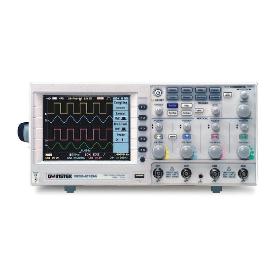
Page 14: Appearance
GDS-2000 Series User Manual Appearance GDS-2064/2104/2204 Front Panel GDS-2062/2102/2202 Front Panel... - Page 15 GETTING STARTED TFT color, 320 x 234 resolution, wide angle view LCD display LCD display. Activates the functions which F1 ~ F5 function appear on the left side of the LCD keys display. Increases/decreases value or Variable knob moves to the next/previous parameter.
- Page 16 GDS-2000 Series User Manual Configures and runs cursor Cursor key measurements (page60). Configures and runs automatic Measure key measurements (page55). Shows Help contents on the LCD Help key display (page46). Saves and recalls waveform, Save/Recall key image, and panel setup (page119).
- Page 17 GETTING STARTED Sets the vertical position of Vertical position knob waveforms (page102). Configures the vertical scale and Channel menu coupling mode for each channel (page102). Selects the vertical scale (page102). Volts/Div knob Accepts input signals. Input Input terminal impedance: 1MΩ±2%. Accepts the DUT ground lead for Ground terminal common ground.
-
Page 18: Rear Panel
GDS-2000 Series User Manual Rear Panel Power switch turns the main power Power switch On ( ) / Off ( Power cord socket Power cord socket accepts AC mains, 100 ~ 240V, 50/60Hz. Fuse socket Fuse socket holds AC main fuse, T2A/250V. - Page 19 GETTING STARTED Accepts 24 pin male GPIB connector GPIB port (optional) for remote control (page153). Holds 2 packs of Li-Ion battery for portable usage Battery packs (page156). (optional) Accepts typeB connector for remote USB slave port control (page150) or PC software connection.
-
Page 20: Display
GDS-2000 Series User Manual Display Power Interface Date/Time or Trigger Acquisition source Memory Bar status mode Image Recall Waveform Display mode Channel Timebase Trigger Waveform status configuration frequency Shows input signal waveforms. Waveforms Channel 1: Yellow Channel 2: Blue Channel 3: Pink Channel 4: Green AC main is the source. - Page 21 GETTING STARTED RS-232C GPIB (optional) Current date and time (page117). Date/Time The ratio and the position of the Memory bar displayed waveform compared with the internal memory (page95). Triggered. Trigger status Not triggered, display not updated. Not triggered, display updated. Trigger stopped.
-
Page 22: Set Up
GDS-2000 Series User Manual Set Up Tilt stand Low angle High angle... -
Page 23: Power Up
GETTING STARTED Power up 1. Connect the power cord to Step the rear panel socket. (No need when using the battery). 2. Turn On the main power switch. : On, : Off. 3. The ON/STBY indicator on the front panel turns red. -
Page 24: First Time Use
GDS-2000 Series User Manual First Time Use This section describes how to connect a signal, Background adjust the scale, and compensate the probe. Before operating GDS-2000 in a new environment, run these steps to make sure the instrument is functionally stable and that you are comfortable operating it. - Page 25 GETTING STARTED Press the Display key, then F1 4. Select vector Display (Type) twice to select the vector waveform waveform. Type Vectors Turn the adjustment point on the probe to make 5. Compensate probe the square waveform edge flat. 6. Start operation Continue with the other operations. Measurement: page47 Configuration: page83 Remote control: page149...
-
Page 26: Quick Reference
GDS-2000 Series User Manual UICK REFERENCE This chapter describes GDS-2000 menu tree, shortcuts to major operations, built-in Help access, and default factory settings. Use them as a handy reference to get a quick access to the functionality. Menu tree / Convention ............27... -
Page 27: Menu Tree / Operation Shortcuts
QUICK REFERENCE Menu Tree / Operation Shortcuts Convention = Press F1 = Press F1 repeatedly = Select one from F1 to F4 and press it F1 ~ F4 = Press F1, then use the Variable knob F1→VAR = Press the function key itself (AutoSet in this case) Auto Set Acquire key Select acquisition mode... - Page 28 GDS-2000 Series User Manual Auto test/Stop key → See Program key (page32) Auto test/Stop CH1 ~ 4 key Select coupling mode Coupling Turn waveform invert On/Off Invert On/ Off Turn bandwidth limit On/Off BW Limit On/ Off Select probe attenuation factor...
- Page 29 QUICK REFERENCE Display key Select waveform display type Display DISPLAY Type Waveform accumulation On/Off Vectors/ Dots Dots , F3 (display refresh when On) Accumulate On/ Off Set display contrast Refresh F4→VAR Contrast Select display grid Hardcopy key → See Utility key (page39) Hardcopy Help key Turn help mode On/Off...
- Page 30 GDS-2000 Series User Manual Math key (1/2) Select math operation (+/– MATH MATH Select channel combination Operation (4CH) Set result position CH1+CH2 CH1+CH2/ CH3+CH4 F4→VAR (2CH) CH1+CH2 Math result vertical scale Position -12div ~ +12div F5→VOLTS/DIV 0.00 Div Unit/Div Math key (2/2)
- Page 31 QUICK REFERENCE Measure key (1/2) Measure Measure MEASURE MEASURE (4CH) CH1/ 2/ 3/ 4 Source 1 (2CH) CH1/ 2/ 1:204mV CH 1 2:24.0mV (4CH) CH1/ 2/ 3/ 4 Vavg Source 2 (2CH) CH1/ 2/ 1:99.3mV CH 2 2:4.28mV Frequency Voltage Voltage/Time/Delay 1:1.000kHz 2:1.500kHz...
- Page 32 GDS-2000 Series User Manual Program key (1/2) Select Program Edit mode Program PROGRAM Edit Select program step Play F2→VAR Step 1 ~ 20 Select edit item Item Menu/Time/ Setup Menu Save edited program Save Program key (2/2) Select Program Play mode...
- Page 33 QUICK REFERENCE Save/Recall key (1/9) Save/Recall Save/Recall SAVE/REC SAVE/REC Default Save To Save Image Setup Image Display Save To Display To Save Refs Refs. Save Recall To Save To Recall Setup Setup Setup Setup Save Recall To Save To Recall Waveform Waveform Waveform...
- Page 34 GDS-2000 Series User Manual Save/Recall key (3/9) Select Save Setup menu Save Setup Save/Recall Select destination Save →VAR Setup Save setup Destination Memory/USB Go to USB flash drive contents edit mode Save File (USB only) To File Utilities Utilities Save/Recall key (4/9)
- Page 35 QUICK REFERENCE Save/Recall key (5/9) Select Save All menu Save All Save/Recall Turn ink saver On/Off Save Ink Saver Select destination On/ Off →VAR Destination Save all Save (USB only) Go to USB flash drive contents File To File Utilities edit mode Utilities Save/Recall key (6/9)
- Page 36 GDS-2000 Series User Manual Save/Recall key (7/9) Select Recall Waveform menu Recall Waveform Save/Recall Select waveform source Recall →VAR Waveform Select waveform destination Source USB/Memory →VAR Recall waveform Destination Recall Go to USB flash drive contents edit mode (USB only)
- Page 37 QUICK REFERENCE Save/Recall key (9/9) Select file/folder or enter into File Utilities sub folder Save/Recall Save/Recall →F1 KEYPAD FILE UTILS Create new folder or rename Enter Select folder/file Character Back F2,F3 (Enter new folder or rename Folder Space menu) Rename →F1 (Enter character) F2 (Backspace) Delete...
- Page 38 GDS-2000 Series User Manual Trigger key (2/5) Select Edge/Pulse trigger type Edge/Pulse MENU Select trigger source TRIGGER Type Pulse Select trigger mode Source (4CH) CH1/2/3/4/Line (2CH) CH1/2/Ext/Line Mode Auto/ Normal/ Select pulse trigger condition Single Auto and pulse width When <...
- Page 39 QUICK REFERENCE Trigger key (4/5) Select trigger slope type Slope/Coupling MENU Select trigger coupling mode TRIGGER Slope Select Frequency Rejection Coupling Rejection Turn Noise Rejection On/Off LF/ HF/ Off Noise Rej On/ Off Go back to previous menu Previous Menu Trigger key (5/5) Set Holdoff time F1→VAR...
- Page 40 GDS-2000 Series User Manual Utility key (1/9) Go to Hardcopy menu Utility UTILITY Go to Interface menu Hardcopy To Hardcopy menu Menu Interface To Interface menu Select buzzer sound Menu / Off English/Chinese(S) Select language Language Chinese(T)/Spanish English Korean/ etc...
- Page 41 QUICK REFERENCE Utility key (3/9) Select Hardcopy function Hardcopy Utility Hardcopy Turn Ink Saver On/Off H-COPY Function SaveImage/ SaveAll/ Printer Save All Select printout color (only in Ink Saver printout mode) On/ Off (Printer only) Gray Color Portrait/ Portrait Select printout ratio (only in Gray Portrait Ratio printout mode)
- Page 42 GDS-2000 Series User Manual Utility key (5/9) Go to Go-NoGo template menu Go-NoGo Utility Select Go-NoGo source channel Go-NoGo To Go-NoGo Template Template menu Edit Select violating condition (4CH) CH1/ 2/ 3/ 4 Source (2CH) CH1/ 2 Violating STOP / STOP+ Start/Stop Go-NoGo test Continue / Cont.+...
- Page 43 QUICK REFERENCE Utility key (7/9) Go to Probe Compensation Utility menu UTILITY ProbeComp To Probe menu Go to Time Set menu Menu Time Set To Time set menu Menu Go to other menu More Utility key (8/9) Select probe compensation signal Probe compensation Utility Set frequency for square wave...
- Page 44 GDS-2000 Series User Manual Utility key (9/9) Select date/time setting Select day/month/year →VAR Select hour/minute →VAR Save date/time setting Go to previous menu...
-
Page 45: Default Settings
QUICK REFERENCE Default Settings Save/Recall Here is the factory installed panel setting which appears when pressing the Save/Recall key→F1 Default (Default Setup). Setup Mode: Normal Memory length: 500 Acquisition Scale: 2V/Div CH1: On, CH2/3/4: Off Channel Coupling: DC Invert: Off BW limit: Off Probe attenuation: x1 Source: CH1... -
Page 46: Built-In Help
GDS-2000 Series User Manual Built-in Help The Help key shows help contents. When a Help functional key is pressed, simple explanations of its major functionalities appear on the display. Applicable keys Acquire Cursor Utility Program Display Measure Save/Recall Auto test/Stop... -
Page 47: Measurement
MEASUREMENT EASUREMENT Basic Channel activation .......... 48 measurement Auto Set ............49 Run/Stop ............50 Horizontal position/scale ....... 51 Vertical position/scale ........52 Probe compensation signal ......53 Automatic Measurement items ........55 measurement Individual mode ..........57 Display All mode ..........59 Use horizontal cursor ........ -
Page 48: Basic Measurement
GDS-2000 Series User Manual Basic Measurement This section describes the basic operations required in capturing and viewing the input signal. For more detailed operations, see the following chapters. Measurements → from page47 Configurations → from page83 Channel activation Activate channel To activate an input channel, press the Channel key. -
Page 49: Measurement Auto Set
MEASUREMENT Auto Set Auto Set function automatically configures the Background panel settings to position the input signal to the best viewing condition. GDS-2000 automatically configures the following parameters. Horizontal scale Vertical scale Trigger source channel 1. Connect the input signal to Panel operation Auto Set GDS-2000 and press the... -
Page 50: Run/Stop
GDS-2000 Series User Manual Run/Stop By default, the waveform on the display is Background constantly updated (Run mode). Freezing the waveform by stopping signal acquisition (Stop mode) allows flexible observation and analysis. To enter the Stop mode, two methods are available: pressing the Run/Stop key or using the Single Trigger mode. -
Page 51: Horizontal Position/Scale
MEASUREMENT Horizontal position/scale For more detailed configuration, see page95. The horizontal position knob Set horizontal position moves the waveform left/right. As the waveform moves, the memory bar appears on the top of the display, indicating the portion of displayed waveform in the memory. -
Page 52: Vertical Position/Scale
GDS-2000 Series User Manual Vertical position/scale For more detailed configuration, see page102. To move the waveform up or Set vertical position down, turn the vertical position knob for each channel. As the waveform moves, the vertical position of the cursor appears at the bottom left corner of the display. -
Page 53: Probe Compensation Signal
MEASUREMENT Probe compensation signal This section introduces how to use Background the probe compensation signal for general usage, in case the DUT signal is not available. For probe compensation details, see page159. Note that the frequency accuracy and duty factor are not guaranteed. - Page 54 GDS-2000 Series User Manual 3. Press F5 (More) twice. More More 4. Press F1 (Wave type) repeatedly to select the wave type. 5. (For square wave only) Frequency To change the frequency, press F2 (Frequency) and use the Variable knob.
-
Page 55: Automatic Measurement
MEASUREMENT Automatic Measurement Automatic measurement function measures and updates major items for Voltage, Time, and Delay type. Measurement items Overview Voltage type Time type Delay type Frequency Vmax Period Vmin RiseTime Vamp FallTime +Width -Width Dutycycle Vavg Vrms ROVShoot FOVShoot RPREShoot FPREShoot Difference between positive... - Page 56 GDS-2000 Series User Manual Averaged voltage of the first Vavg cycle RMS (root mean square) Vrms voltage Rise overshoot voltage ROVShoot Fall overshoot voltage FOVShoot Rise preshoot voltage RPREShoot Fall preshoot voltage FPREShoot Frequency of the waveform Time Freq measurement...
-
Page 57: Measurement Individual Mode
MEASUREMENT Time between: Source 1 first falling edge and Source 2 first rising edge Time between: Source 1 first falling edge and Source 2 first falling edge Time between: Source 1 first rising edge and Source 2 last rising edge Time between: Source 1 first rising edge and Source 2 last falling edge... - Page 58 GDS-2000 Series User Manual 3. The selection menu appears. Select Source 1 Press F1 (Source 1) measurement CH 1 item repeatedly to select the first source channel. 4. Press F2 (Source 2) Source 2 repeatedly to select the CH 2 second source channel.
-
Page 59: Display All Mode
MEASUREMENT Display All mode Display All mode shows and updates all items from Voltage and Time type measurement. 1. Press the Measure key View Measure measurement twice. result Measure 2. Press the channel for which the measurement results need to be observed. 3. -
Page 60: Cursor Measurement
GDS-2000 Series User Manual Cursor Measurement Cursor line, horizontal or vertical, shows the position and value of the waveform and math operation result. Use horizontal cursor 1. Press the Cursor key. Panel operation/ Cursor Range 2. Press F1 (Source) repeatedly Source to select the source channel. - Page 61 MEASUREMENT Parameter Time position of the left cursor Time position of the right cursor ∆ The time distance between the left and right cursor The time distance (∆) converted to frequency 5. Use the Variable knob to move the cursor left or right. The F4 content changes accordingly.
-
Page 62: Measurement Use Vertical Cursor
GDS-2000 Series User Manual Use vertical cursor 1. Press the Cursor key. Panel operation/ Cursor Range 2. Press F1 (Source) repeatedly Source to select the source channel. Range 4CH model CH1, 2, 3, 4, Math 2CH model CH1, 2, Math 3. - Page 63 MEASUREMENT 5. Use the Variable knob to move the cursor up or down. The F5 content changes accordingly. Example The FFT Math has different F5 Note: FFT Math content. For FFT math details, see page67. Magnitude of the left cursor Magnitude of the right cursor ∆...
-
Page 64: Math Operation
GDS-2000 Series User Manual Math Operation Overview Math operation runs addition, subtraction, Background multiplication, or FFT using the input signals and shows the result on the display. The resulted waveform characteristics can be measured using the cursors. Adds amplitude of two signals. -
Page 65: Math Operation Addition/Subtraction/Multiplication
MEASUREMENT Frequency resolution Not good Flattop FFT window Amplitude resolution Good Amplitude measurement on Suitable for..periodic waveform Frequency resolution Very good Rectangular FFT window Amplitude resolution Bad Single-shot phenomenon Suitable for..(this mode is the same as having no window at all) Frequency resolution Bad Blackman FFT window... - Page 66 GDS-2000 Series User Manual 4. (For 4CH model only) press CH1+CH2 F2 repeatedly to select the channel pairs, 1&2 or 3&4. 5. The math measurement Unit/Div result appears on the display. The vertical scale (fixed) of math waveform appears in F5 (Unit/div).
-
Page 67: Fft
MEASUREMENT 1. Press the Math key. Panel operation MATH 2. Press F1 (Operation) Operation repeatedly to select FFT. 3. Press F2 repeatedly to select Source the source channel. 4. Press F3 repeatedly to select Window the FFT window type. Hanning 5. - Page 68 GDS-2000 Series User Manual 6. To move the FFT waveform Position vertically, press F4 0.00 Div (Position) and use the Variable knob. –12.00 Div ~ +12.00 Div Range 7. To select the vertical scale of Unit/Div FFT waveform, press F5 (Unit/Div) repeatedly.
-
Page 69: Go-Nogo Test
MEASUREMENT Go-NoGo Test Overview Go-NoGo test checks if a waveform fits inside the Background user-specified maximum and minimum amplitude boundary (template). The test result comes out in three ways: menu contents, buzzer sound, and pulse signal output from the rear panel terminal. Test parameters item default setting setup details... -
Page 70: Go-Nogo Test Edit: Buzzer Sound
GDS-2000 Series User Manual Edit: Buzzer sound 1. Press the Utility key. Panel operation Utility 2. Press F3 repeatedly to select the buzzer for test fail (NoGo) notification. High pitch Middle pitch Low pitch Sound Off The buzzer setting also affects the vertical Note resolution calibration (page158) –... -
Page 71: Edit: Source Signal
MEASUREMENT Edit: Source signal 1. Press the Utility key. Utility 2. Press F5 (More). More 3. Press F3 (Go-NoGo Menu). Go-NoGo Menu 4. Press F2 (Source) repeatedly Source to select the channel to be tested. (Note: the selected channel is automatically activated) Edit: Continue or stop after NoGo 1. -
Page 72: Edit: Template (Boundary)
GDS-2000 Series User Manual The test stops when the NoGo Stop condition is met. The buzzer does not sound. The test stops and the buzzer Stop+ sounds when the NoGo condition is met. The test continues even when Continue the NoGo condition is met. The buzzer does not sound. - Page 73 MEASUREMENT Creates the upper and lower boundary Auto together from an input signal, not from internally stored waveform. Advantage: No need to store the waveforms prior to this selection. Disadvantage: The template shape is proportional to the source signal. The distance (allowance) between the source signal and upper/lower template are always symmetrical.
- Page 74 GDS-2000 Series User Manual (marked as waveform “A” in thd display) Maximum boundary: RefA, W1 ~ 20 internal memory (marked as waveform “B” in the display) Minimum boundary: RefB, W1 ~ 20 internal memory 8. Press F3 (Position). Use the...
- Page 75 MEASUREMENT 1. Make sure the source signal, on which the Auto setting templates are based, appears on the display. 2. Press the Utility key. Utility 3. Press F5 (More). More 4. Press F3 (Go-NoGo Menu). Go-NoGo Menu 5. Press F1 (Template Edit). Template Edit 6.
-
Page 76: Run Go-Nogo Test
GDS-2000 Series User Manual 10. When the templates are set, Save & press F4 (Save & Create) to Create save it. Run Go-NoGo test This section assumes all Go-NoGo settings (page69) are completed. 1. Press the Utility key. Panel operation Utility 2. - Page 77 MEASUREMENT 5. Press F4 (Go-NoGo). The Go-NoGo Go-NoGo test starts running and stops according to the continue/stop condition (page71). To stop the test manually, Press F4 again. 6. The test results appear in F5 Ratio: menu. The denominator (lower side) shows the number of completed test.
-
Page 78: Program
GDS-2000 Series User Manual Program Overview Program function measures input signals using Background cursors or automatic measurement functions, in user-defined sequence, duration, loop count, and panel settings. This feature is useful for automated and repetitive measurement, such as in assembly line or quality inspection test. -
Page 79: Program Edit Program
MEASUREMENT Edit program This section assumes that the panel setting is already defined and saved (step 1 and 2 in the previous page). 1. Press the Program key. The Panel operation Program display changes into program edit mode. 2. Press F1 (Edit/Play) to Edit select the Edit side. - Page 80 GDS-2000 Series User Manual Selects the panel setup stored in the Setup internal memory. S01 ~ S20. For panel setup store/recall details, see page129 (save) or page139 (recall). Selects the measured item: Cursor Menu or Automatic measurement. Sets the duration of the step, 1 ~ 99 Time seconds or user control (Run/Stop).
-
Page 81: Run Program
MEASUREMENT Run program This section assumes that the program editing (see previous page) is completed. 1. Press the Program key. The Panel operation Program display changes into program mode. 2. Press F1 (Edit/Play) Edit repeatedly to select the Play Play side. - Page 82 GDS-2000 Series User Manual 4. Press F3 (From/To) to select From: 1 the From: side. Use the To: 4 Variable knob to select the program start step: 1 ~ 20. The “S” mark appears in the selected step. 5. Press F3 (From/To) to select From: 1 the To: side.
-
Page 83: Configuration
CONFIGURATION ONFIGURATION Acquisition Select acquisition mode ........85 Select waveform memory length ...... 87 Real time vs Equivalent time sampling mode .. 90 Display Select waveform drawing (vector/dot) ..... 91 Accumulate waveform ........92 Set display contrast......... 93 Freeze the waveform ........93 Select display grid ........... - Page 84 GDS-2000 Series User Manual Trigger Trigger type overview ........106 Trigger parameter overview ......107 Use edge trigger ..........110 Use advanced delay trigger (2CH model) ..111 Use video trigger ........... 113 Use pulse width trigger ........114 System View system information .......
-
Page 85: Acquisition
CONFIGURATION Acquisition Acquisition process samples the analog input signals and converts them into digital format for internal processing. Select acquisition mode 1. Press the Acquire key. Panel operation Acquire 2. Select the acquisition mode Normal from F1 (Normal) ~ F3 (Average). - Page 86 GDS-2000 Series User Manual Example Normal Peak Detect Average (2 times) Average (256 times) 1. One of the probe Peak detect effect compensation waveforms using probe comp. waveform can demonstrate peak detection mode. Connect the probe to the probe compensation output.
-
Page 87: Select Waveform Memory Length
CONFIGURATION 6. Press the Acquire key. Acquire 7. Press F2 (Peak Detect) or F1 Normal (Normal) and see that in the Peak detection mode, spike Peak noise is captured. Detect Peak Detect Normal Select waveform memory length Memory length defines the amount of waveform Background data (points) included in each trigger event. - Page 88 GDS-2000 Series User Manual 2. Press F5 (Mem Leng) to Mem Leng select the memory length (points), short or long. Short memory length; useful for Range (memory catching high frequency signal. point) Long memory length when three or 5000 four channels are active.
- Page 89 CONFIGURATION 1. One of the probe Long memory compensation waveform effect using probe comp. waveform can demonstrate long memory mode. Connect the probe to the output. 2. Press the Utility key. Utility 3. Press F5 (More) twice. More 4. Press F1 (Wave Type) and select the waveform.
-
Page 90: Real Time Vs Equivalent Time Sampling Mode
GDS-2000 Series User Manual Real time vs Equivalent time sampling mode GDS-2000 automatically switches between two Background sampling modes, Real-time and Equivalent-time, according to the number of active channel and sampling rate. One sampled data is used to Parameter Real-time reconstruct a single waveform. -
Page 91: Display
CONFIGURATION Display Display menu defines how the waveforms and parameters appear on the main LCD display. Select waveform drawing (vector/dot) 1. Press the Display key. Panel operation Display 2. Press F1 (Type) repeatedly Type to select the waveform Dots drawing. Only the sampled dots are displayed. -
Page 92: Accumulate Waveform
GDS-2000 Series User Manual Accumulate waveform Accumulation preserves the old waveform Background drawings and overwrites new waveforms on top of it. It is useful for observing waveform variation. 1. Press the Display key. Panel operation Display 2. Press F2 (Accumulate) to... -
Page 93: Set Display Contrast
CONFIGURATION Set display contrast 1. Press the Display key. Panel operation Display 2. Press F4 (Contrast). Contrast 3a. Turn the Variable knob left to lower the contrast (dark display). Contrast 3b. Turn the Variable knob right to raise the contrast (bright display). -
Page 94: Select Display Grid
GDS-2000 Series User Manual Select display grid 1. Press the Display key. Panel operation Display 2. Press F5 (Grid type) repeatedly to select the grid. Shows the full grid; X and Y axis for Range each division. Shows only the center X and Y frame. -
Page 95: Horizontal View
CONFIGURATION Horizontal View This section describes how to set the horizontal scale, position, and waveform display mode. Move waveform position horizontally The horizontal position knob Panel operation moves the waveform left/right. As the waveform moves, the memory bar appears on the top of the display indicating the portion of displayed waveform in the memory. -
Page 96: Select Horizontal Scale
GDS-2000 Series User Manual Select horizontal scale To select the timebase (scale), Select horizontal scale turn the TIME/DIV knob; left (slow) or right (fast). Range 1ns/Div ~ 10s/Div, 1-2-5 increment The corresponding sampling rate appears on the upper side of the display. The timebase indicator appears on the lower side. -
Page 97: Select Waveform Update Mode
CONFIGURATION Select waveform update mode The display update mode is Background switched automatically or manually according to timebase and trigger. The indicator on the bottom left of the display shows the current mode. Updates the whole displayed waveform at Main mode once. - Page 98 GDS-2000 Series User Manual Updates and moves the waveform Roll mode gradually from the right side of the display to the left. Manually selected when the timebase (sampling rate) is slow. ≥250ms/div (≤100Sa/s) Timebase all modes Trigger Roll mode indicator...
-
Page 99: Zoom Waveform Horizontally
CONFIGURATION Zoom waveform horizontally 1. Press the Horizontal Menu Panel operation/ HORI MENU key. range 2. Press F2 (Window) key. Window 3. The WINDOW indicator, which shows the zoom range, appears on the bottom left corner of the display. Use the horizontal position knob to move the zoom range sideways, and TIME/DIV knob to change... -
Page 100: Show Waveform In X-Y Mode
GDS-2000 Series User Manual 4. Press F3 (Window Zoom). Window The specified range gets Zoom zoomed. The ZOOM indicator appears on the bottom left side of the display. Zoom Range 5. To go back to the original Main view, press F1 (Main). - Page 101 CONFIGURATION 3. Press the Horizontal menu HORI MENU key. 4. Press F5 (XY). The display shows two waveforms in X- Y format; Channel 1 as X- axis, Channel 2 as Y-axis. 5. Horizontal Position knob and Time/Div knob are disabled under the X-Y mode.
-
Page 102: Vertical View (Channel)
GDS-2000 Series User Manual Vertical View (Channel) This section describes how to set the vertical scale, position, and coupling mode. Move waveform position vertically To move the waveform up or Panel operation down, turn the vertical position knob for each channel. -
Page 103: Select Coupling Mode
CONFIGURATION Select coupling mode 1. Press the Channel key. Panel operation 2. Press F1 (Coupling) Coupling repeatedly to select the coupling mode. DC coupling mode. The whole Range portion (AC and DC) of the signal appears on the display. Ground coupling mode. The display shows only the zero voltage level as a horizontal line. -
Page 104: Invert Waveform Vertically
GDS-2000 Series User Manual Invert waveform vertically 1. Press the Channel key. Panel operation 2. Press F2 (Invert) to invert Invert the waveform. Example CH2 (below) Invert Off CH2 (below) Invert On Limit bandwidth Bandwidth limitation puts the input signal into a Background 20MHz (−3dB) low-pass filter. -
Page 105: Select Probe Attenuation Level
CONFIGURATION Example BW Limit Off BW Limit On Select probe attenuation level A signal probe has an attenuation switch to lower Background the original DUT signal level to the oscilloscope input range, if necessary. The probe attenuation selection adjusts the vertical scale so that the voltage level on the display reflects the real value on DUT. -
Page 106: Trigger
GDS-2000 Series User Manual Trigger Trigger configures the condition GDS-2000 captures the incoming signal. Trigger type overview Triggers when the signal crosses an amplitude Edge (+Delay) threshold in either positive or negative slope. (for 2CH models only) The advanced Delay trigger... -
Page 107: Trigger Parameter Overview
CONFIGURATION Trigger parameter overview CH1 ~ 4 Channel 1 ~ 4 input signals Trigger source AC mains signal Line EXT TRIG (For 2CH models only) external trigger input signal GDS-2000 generates an internal trigger if Trigger mode Auto there is no trigger event, to make sure waveforms are constantly updated regardless of trigger events. - Page 108 GDS-2000 Series User Manual National Television System Committee Video standard NTSC (video trigger) Phase Alternative by Line SECAM SEquential Couleur A Memoire Positive polarity Sync polarity (video trigger) Negative polarity Selects the trigger point in the video signal. Video line...
- Page 109 CONFIGURATION Triggers on AC+DC component. Puts a high-pass filter and rejects the Frequency frequency below 50kHz. rejection Puts a low-pass filter and rejects the frequency above 50kHz. Rejects noise signal. Noise rejection Setup Holdoff and Auto level Holdoff function defines the waiting period before Background GDS-2000 starts triggering again after a trigger point.
-
Page 110: Use Edge Trigger
GDS-2000 Series User Manual Use edge trigger 1. Press the Trigger menu key. Panel operation MENU 2. Press F1 repeatedly to select Type edge trigger. The edge Edge trigger indicator appears at the bottom of the display. From left: channel, edge trigger, slope 3. -
Page 111: Use Advanced Delay Trigger (2Ch Model)
CONFIGURATION 8. Press F3 (Rejection) to select Rejection the frequency rejection mode. LF, HF, Off Range 9. Press F4 (Noise Rej) to turn Noise Rej the noise rejection On/Off. On, Off Range 10. Press F5 (Previous menu) to Previous go back to the previous Menu menu. - Page 112 GDS-2000 Series User Manual 4. Press F4 (Ext) repeatedly to Ext: select the threshold level for the external trigger input. TTL (1.48V), ECL (1.35V), Range User (–12V ~ +12V) 5. Press F5 (Slope/Coupling) Slope / to set the slope and coupling...
-
Page 113: Use Video Trigger
CONFIGURATION Use video trigger 1. Press the Trigger menu key. Panel operation MENU 2. Press F1 repeatedly to select Type video trigger. The video Video trigger indicator appears at the bottom of the display. From left: channel, video trigger, polarity 3. -
Page 114: Use Pulse Width Trigger
GDS-2000 Series User Manual Use pulse width trigger 1. Press the Trigger menu key. Panel operation MENU 2. Press F1 repeatedly to select Type pulse width trigger. The Pulse pulse width trigger indicator appears at the bottom of the display. - Page 115 CONFIGURATION 7. Press F1 (Slope) repeatedly to select the trigger slope, which also appears at the bottom of the display. Rising edge, falling edge Range 8. Press F2 (Coupling) repeatedly to select the trigger coupling. DC, AC Range 9. Press F3 (Rejection) to select Rejection the frequency rejection mode.
-
Page 116: System Info / Language / Clock
GDS-2000 Series User Manual System Info / Language / Clock This section describes how to set the interface, beeper, language, time/date, and probe compensation signal. View system information 1. Press the Utility key. Panel operation Utility 2. Press F5 (More). -
Page 117: Set Date And Time
CONFIGURATION Spanish Japanese Russian German Dutch Polish Italian French Portuguese 1. Press the Utility key. Panel operation Utility 2. Press F4 (Language) Language repeatedly to select the English language. Set date and time 1. - Page 118 GDS-2000 Series User Manual 5. Press F4 (Save) to confirm Save the value. 6. Press F1 (Date) to switch to Time the Time setting menu. 7. Press F2 (Hour/ Minute) repeatedly. Use the Variable knob to change the value. 0 ~ 23...
-
Page 119: Save/Recall
SAVE/RECALL AVE/RECALL File format / Display image file format ......120 Utility Waveform file format ........120 Setup file format ........... 122 USB flash drive file utility ......123 Save File type/source/destination ......128 Save panel setting ......... 129 Save waveform ..........130 Save All ............ -
Page 120: File Format/Utility
GDS-2000 Series User Manual File Format/Utility Display image file format DSxxxx.bmp or Axxxx.bmp (Windows bitmap Format format) The current display image in 234 x 320 pixels, color Contents format. The background color can be inverted (Ink saver function). Waveform file format DSxxxx.csv or Axxxx.csv (Comma-separated... - Page 121 SAVE/RECALL The waveform data can be used for detailed Contents: waveform data analysis. It consists of horizontal and vertical position of the waveform for the entire memory length. One division includes 25 points of horizontal and vertical data. The vertical point starts from the center line.
-
Page 122: Setup File Format
GDS-2000 Series User Manual Setup file format DSxxxx.set or Axxxx.set (proprietary format) Format The setup file saves or recalls the following setting. mode memory length Acquire Contents source channel cursor on/off Cursor cursor location dots/vectors... -
Page 123: Usb Flash Drive File Utility
SAVE/RECALL USB flash drive file utility For USB flash drive, file deletion, folder creation, Background file/folder rename are available from the front panel. This feature is not available for internally stored files. 1. Connect the drive to the Panel operation Front Rear front or rear panel USB port. - Page 124 GDS-2000 Series User Manual 4. Use the Variable knob to move the cursor. Press F1 (Select) to go into the folder or go back to the previous directory level. Select Go back to the root directory Go back to the previous...
- Page 125 SAVE/RECALL 3. When editing is completed, Save press F4 (Save). A new folder or a new folder/file name is created. 4. Press F5 (Previous Menu) to Previous go back to the previous Menu menu. Delete folder/file 1. Move the cursor to the Delete folder or file location and press F4 (Delete).
-
Page 126: Quick Save (Hardcopy)
GDS-2000 Series User Manual Quick Save (HardCopy) The Hardcopy key works as a Background Hardcopy shortcut for saving or printing out information. Once set, subsequent file saving only requires pressing the Hardcopy key. Hardcopy key can be configured into three operations: save image, save all (image, waveform, setup), and printing. - Page 127 SAVE/RECALL 1. Connect the drive to the Panel operation Front Rear front or rear panel USB port. Note: Only one host connection, front or rear, is allowed at a time. 2. Press the Utility key. Utility 3. Press F1 (Hardcopy Menu). Hardcopy Menu 4.
-
Page 128: Save
GDS-2000 Series User Manual Save File type/source/destination Item Source Destination Front panel settings Internal memory: S1 ~ Panel setup (DSxxxx.set) External memory: USB Channel 1 ~ 4 Internal memory: Waveform data Reference waveform A ~ (DSxxxx.csv) -
Page 129: Save Panel Setting
SAVE/RECALL Save panel setting 1. (For saving to an external Panel operation Front Rear USB flash drive) Connect the drive to the front or rear panel USB port. Note: Only one host connection, front or rear, is allowed at a time. 2. -
Page 130: Save Waveform
GDS-2000 Series User Manual External flash drive, no practical limitation on the amount of file. When saved, the setup file is placed in the root directory. 5. Press F4 (Save) to confirm Save saving. When completed, a message appears at the bottom of the display. - Page 131 SAVE/RECALL 4. Press F2 (Source). Use the Source Variable knob to select the source signal. Channel 1 ~ 2 signal CH1 ~ CH2 (2CH model) Channel 1 ~ 4 signal CH1 ~ CH4 (4CH model) Math operation result Math (page64) Internally stored reference RefA ~ D waveforms A ~ D...
- Page 132 GDS-2000 Series User Manual External flash drive, no practical limitation on the amount of file. When saved, the waveform file is placed in the root directory. Internal reference waveform, A~D 6. Press F4 (Save) to confirm Save saving. When completed, a message appears at the bottom of the display.
- Page 133 SAVE/RECALL 3. Press F5 (More). More 4. Press F1 (Save Image). The Save display shows the available Image file destinations. 5. Press F2 (Ink Saver) Ink Saver repeatedly to invert the background color (On) or not (Off). Ink Saver On (normal) Ink Saver Off (inverted) 6.
-
Page 134: Save All
GDS-2000 Series User Manual External flash drive, no practical limitation on the amount of file. When saved, the image file is placed in the root directory. 7. Press F4 (Save) to confirm Save saving. When completed, a message appears at the bottom of the display. - Page 135 SAVE/RECALL 4. Press F2 (Save All). The Save display shows the available file destinations. The following files are saved, contained in a folder. Two types of setups are saved: Setup file the current panel setting and (Axxxx.set) the last internally saved setting (one of S1 ~ S20).
- Page 136 GDS-2000 Series User Manual Ink Saver On (normal) Ink Saver Off (inverted) 6. Press F3 (Destination). Use Destination the Variable knob to select the file name. External flash drive, no practical limitation on the amount of file. When saved, the folder is placed in the root directory.
-
Page 137: Recall
SAVE/RECALL Recall File type/source/destination Item Source Destination Current front panel Factory installed Default panel setup setting Internal memory: A ~D Current front panel Reference waveform Internal memory: S1 ~ Current front panel Panel setup (DSxxxx.set) External memory: USB ... - Page 138 GDS-2000 Series User Manual Mode: Normal Memory length: 500 Acquisition Scale: 2V/Div CH1: On, CH2/3/4: Off Channel Coupling: DC Invert: Off BW limit: Off Probe attenuation: x1 Source: CH1 Horizontal: None Cursor Vertical: None Type: Dots Accumulate: Off Display Graticule:...
-
Page 139: Recall Waveform
SAVE/RECALL Recall reference waveform on the display 1. The reference waveform must be stored in Panel operation advance. See page for waveform store details. 2. Press the Save/Recall key. Save/Recall 3. Press F2 (Display Refs). The Display reference waveform display Refs. -
Page 140: Recall Waveform
GDS-2000 Series User Manual Recall panel setting 1. (For recalling from an Panel operation Front Rear external USB flash drive) Connect the drive to the front or rear panel USB port. Note: Only one host connection, front or rear, is allowed at a time. - Page 141 SAVE/RECALL 5. Press F2 (Source) repeatedly Source to select the file source, internal memory or external USB. Use the Variable knob to change the memory location (S1 ~ S20) or the file name (DSxxxx.set). Internal memory, S1 ~ S20 Memory External flash drive, no practical limitation on the amount of file.
-
Page 142: Recall Waveform
GDS-2000 Series User Manual Recall waveform 1. (For recalling from an Panel operation Front Rear external USB flash drive) Connect the drive to the front or rear panel USB port. Note: Only one host connection, front or rear, is allowed at a time. - Page 143 SAVE/RECALL 5. Press F2 (Source) repeatedly Source to select the file source, internal memory or external USB. Use the Variable knob to change the memory location (S1 ~ S20) or the file name (DSxxxx.csv). Internal memory, W1 ~ W20 Memory External flash drive, no practical limitation on the amount of file.
- Page 144 GDS-2000 Series User Manual Recall image 1. Connect the USB drive to Panel operation Front Rear the front or rear panel USB port. Note: Only one host connection, front or rear, is allowed at a time. 2. Press the Save/Recall key.
- Page 145 SAVE/RECALL 6. To show the image on the Ref Image display, press F3 (Ref Image) ON or F4 (Recall). Recall 7. The image appears on the display and the “R” indicator appears at the top left corner of the display. 8.
-
Page 146: Print Out
GDS-2000 Series User Manual RINT OUT Display printout is also available using proprietary PC software, downloadable from GWInstek website. Overview Listed below are the steps that have to be followed Printout step when printing out the display image through USB connector. - Page 147 PRINT OUT 2 Configure interface 1. Press the Utility key. Panel operation Utility 2. Press F2 (Interface menu). Interface Menu 3. Press F1 (Type) repeatedly Type to select USB. 4. Press F5 (Previous menu). Previous Menu 5. Press F1 (Hardcopy menu). Hardcopy Menu 6.
- Page 148 GDS-2000 Series User Manual 4. To invert the color for the Ink Saver saved or printed display image, press F2 (Ink Saver) and turn On the Ink Saver. Ink Saver On (normal) Ink Saver Off (inverted) 5. To select black/white or...
-
Page 149: Remote Control Config
REMOTE CONTROL CONFIG EMOTE CONTROL CONFIG This chapter describes basic configuration of IEEE488.2 based remote control. For command list, refer to the programming manual downloadable from GWInstek website, www.gwinstek.com Configuration Configure USB interface ........ 150 Configure RS-232C interface ......151 Configure GPIB interface (optional) .... -
Page 150: Interface Configuration
GDS-2000 Series User Manual Interface Configuration Configure USB interface PC side connector Type A, host configuration Type B, slave GDS-2000 side connector 1.1/2.0 (full speed) Speed 1. Press the Utility key. Panel operation Utility 2. Press F2 (Interface Menu). Interface Menu 3. - Page 151 REMOTE CONTROL CONFIG Configure RS-232C interface DB-9, Male RS-232C Connector configuration 2400, 4800, 9600, 19200, 38400 Baud rate None, Odd, Even Parity 8 (fixed) Data bit 1, 2 Stop bit 1. Press the Utility key. Panel operation Utility 2. Press F2 (Interface Menu). Interface Menu 3.
- Page 152 GDS-2000 Series User Manual None, Odd, Even Range 9. Connect the RS-232C cable to the rear panel port: DB-9 male connector. For functionality check see page155. 1 2 3 4 5 2: RxD (Receive data) Pin assignment 3: TxD (Transmit data)
- Page 153 REMOTE CONTROL CONFIG Configure GPIB interface (optional) The optional GPIB module is available as a GPIB module separate kit. Follow the instruction to install the installation module properly. 1. Turn Off the GDS-2000 power switch. 2. Take off two screws and remove the rear panel GPIB module cover.
- Page 154 GDS-2000 Series User Manual 4. The interface icon at display top changes to GPIB. 5. Press F2 (Address). Use the Address Variable knob to change the GPIB address. 1 ~ 30 Range 6. Connect the GPIB cable to the rear panel port: 24-pin female connector.
- Page 155 REMOTE CONTROL CONFIG USB/RS-232C remote control software Invoke the terminal application such as MTTTY Terminal (Multi-Threaded TTY). For RS-232C, set the COM application (USB/RS-232C) port, baud rate, stop bit, data bit, and parity accordingly. To check the COM port No, see the Device Manager in the PC.
-
Page 156: Battery Operation
GDS-2000 Series User Manual ATTERY OPERATION The optional battery allows portable operations such as field applications. Battery packs and related internal components are factory installed items: contact the service center for new installation. Never insert or remove the battery while the Warning power is On. - Page 157 BATTERY OPERATION 3. Insert the battery packs and close the cover. 4. Turn On the power and make sure the battery icon appears at the top left corner of the display. Li-Ion battery x 2, 11.1V average Rating Type Running time 3 hours typical Charging time 8 hours typical when Power Off 16 hours typical when Power On 1.
-
Page 158: Maintenance
GDS-2000 Series User Manual AINTENANCE Two types of maintenance operations are available: calibrate vertical resolution, and compensate the probe. Run these operations when using GDS-2000 in a new environment. Vertical Resolution Calibration 1. Press the Utility key. Panel operation Utility 2. -
Page 159: Probe Compensation
MAINTENANCE 8. The calibration for Channel1 Ch1 calibration 1/3 starts and ends automatically, in less than 5 minutes. 9. When finished, connect the Done!! calibration signal to Channel2 and press F5. Channel2 calibration starts. 10. (for 4 Channel model only) Repeat the above step for Channel 3 and 4. - Page 160 GDS-2000 Series User Manual 3. Press F5 (More) twice. More 4. Press F1 (ProbeComp ProbeComp Menu). Menu 5. Press F1 (Wavetype) repeatedly to select the standard square wave. 6. Press the Auto Set key. The Auto Set compensation signal appears on the display.
-
Page 161: Faq
• I pressed the Power (On/Standby) key on the front panel but nothing happens. • I connected the signal but it does not appear on the display. • I want to remove the (Measurement result / FFT result / Help contents) from the display. - Page 162 GDS-2000 Series User Manual I want to remove the (Measurement result / FFT result / Help contents) from the display. To clear automatic measurement result, press the Measure key twice, then Press F4 (OFF). See page55 for details. To clear FFT result, press the Math key twice. See page64 for details.
- Page 163 The display image printout is too dark on the background. Use the Inksaver function which reverses the background color. For details, see page146. I want to install the optional battery pack. I put the battery pack in but it is not working. The battery pack needs additional internal components to work properly.
-
Page 164: Appendix
GDS-2000 Series User Manual PPENDIX Fuse Replacement 1. Take off the power cord and remove the fuse Step socket using a minus driver. 2. Replace the fuse in the holder. T2A, 250V Rating... -
Page 165: Gpib Module Installation
APPENDIX GPIB Module Installation For GPIB interface and remote control details, see page149. GPIB module GPIB kit contents Programming manual (programming manual is also downloadable from GWInstek website). 1. Turn Off the GDS-2000 power Step switch. 2. Take off two screws and remove the rear panel GPIB module cover. -
Page 166: Gds-2000 Specifications
GDS-2000 Series User Manual GDS-2000 Specifications The specifications apply when GDS-2000 is powered on for at least 30 minutes under +20°C~+30°C. Model-specific GDS-2062 Channels Bandwidth DC ~ 60MHz (–3dB) Rise time 5.8ns approx. GDS-2064 Channels Bandwidth DC ~ 60MHz (–3dB) Rise time 5.8ns approx. - Page 167 APPENDIX Trigger Sources CH1, CH2, Line, EXT(2ch model only), CH3, CH4(4ch model only) Modes Auto-Level, Auto, Normal, Single, TV, Edge, Pulse Width, Time-Delay, Event- Delay(2ch model only) Coupling AC, DC, LFrej, HFrej, Noise rej Sensitivity DC~25MHz: Approx. 0.5div or 5mV 25MHz~max: Approx.
- Page 168 GDS-2000 Series User Manual Auto Counter Resolution: 6 digits Accuracy: ±2% Signal source: All available trigger source except the Video trigger Control Panel Auto Set Automatically adjust Vertical Volt/div, Function Horizontal Time/div, and Trigger level Save Setup Internal memory: 20 sets...
-
Page 169: Probe Specifications
–10°C ~ 55°C Condition Relative Humidity ≤85% @35°C Safety Standard IEC 1010-1 CAT II * Note: GW Instek reserves the right to change the probe model type (GTP-060A, GTP-150A, GTP-250A) at anytime without notice for probe types of similar specification. - Page 170 GDS-2000 Series User Manual Declaration of Conformity GOOD WILL INSTRUMENT CO., LTD. No. 7-1, Jhongsing Rd, Tucheng City, Taipei County 236. Taiwan. GOOD WILL INSTRUMENT (SUZHOU) CO., LTD. No. 69 Lushan Road, Suzhou New District Jiangsu, China. declare that the below mentioned product...
-
Page 171: Index
INDEX NDEX 2-4 channel difference ....11 coupling mode ......103 menu tree ........28 AC coupling ......103 cursor ........... 60 acquisition ........85 menu tree ........28 menu tree ........27 shortcut .......... 28 addition ........65 specification ......... 167 menu tree ........ - Page 172 GDS-2000 Series User Manual safety instruction ......7 scale ..........96 equivalent time sampling ..90 shortcut .......... 29 specification ......... 167 external trigger ......107 IEC 1010-1 ......... 169 input terminal ....... 17 initialization........ 24 specification ......... 167 falling time measure....56 ink saver FFT ..........
- Page 173 INDEX compensation menu tree ..... 43 serial number ......116 compensation signal overview ... 53 service operation faq ..........162 about disassembly ......6 memory length demonstration .. 89 contact .......... 163 package list ........13 setup peak detect demonstration ..86 default contents ......
- Page 174 GDS-2000 Series User Manual key overview ......... 15 waveform menu tree ........40 accumulation ......... 92 shortcut .......... 40 file contents ......... 121 vector waveform ......91 how to recall ........ 142 vertical ........102 how to save ........130 invert waveform ......
Need help?
Do you have a question about the GDS-2000 Series and is the answer not in the manual?
Questions and answers