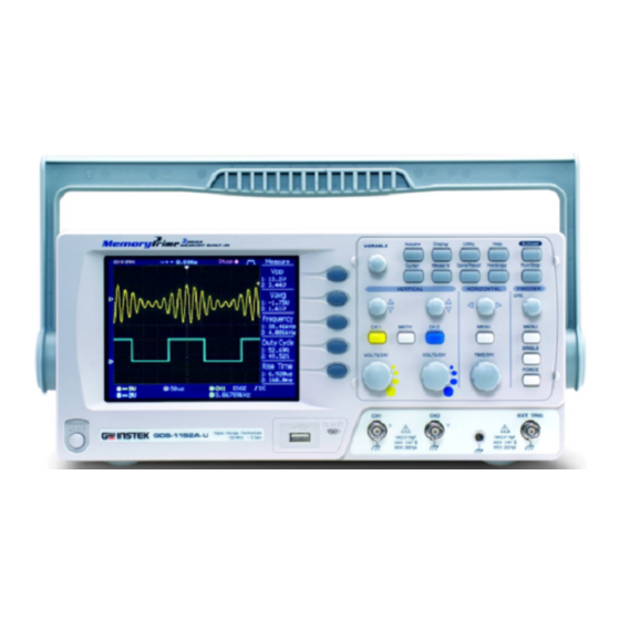
GW Instek GDS-1000A Series User Manual
Digital storage oscilloscope
Hide thumbs
Also See for GDS-1000A Series:
- User manual (135 pages) ,
- Programming manual (31 pages) ,
- User manual (63 pages)
Table of Contents
Advertisement
Quick Links
Download this manual
See also:
Programming Manual
Digital Storage Oscilloscope
GDS-1000A Series
USER MANUAL
GW INSTEK PART NO. 82DS-1102AMB1
ISO-9001 CERTIFIED MANUFACTURER
September 2009 edition
This manual contains proprietary information, which is protected by
copyright. All rights are reserved. No part of this manual may be
photocopied, reproduced or translated to another language without
prior written consent of Good Will Corporation.
The information in this manual was correct at the time of printing.
However, Good Will continues to improve its products and therefore
reserves the right to change the specifications, equipment, and
maintenance procedures at any time without notice.
Good Will Instrument Co., Ltd.
No. 7-1, Jhongsing Rd., Tucheng City, Taipei County 236, Taiwan.
Advertisement
Table of Contents

Related Manuals for GW Instek GDS-1000A Series


Summary of Contents for GW Instek GDS-1000A Series
-
Page 1: Digital Storage Oscilloscope
Digital Storage Oscilloscope GDS-1000A Series USER MANUAL GW INSTEK PART NO. 82DS-1102AMB1 September 2009 edition This manual contains proprietary information, which is protected by copyright. All rights are reserved. No part of this manual may be photocopied, reproduced or translated to another language without prior written consent of Good Will Corporation. -
Page 2: Table Of Contents
TABLE OF CONTENTS GDS-1000A Series User Manual Trigger key 2/6 ..............34 Trigger key 3/6 ..............35 Table of Contents Trigger key 4/6 ..............35 Trigger key 5/6 ..............36 Trigger key 6/6 ..............36 ... - Page 3 APPENDIX ............ 124 File Structures ..............93 Fuse Replacement............124 Display image file format ............. 93 GDS-1000A Series Specifications ........125 Waveform file format ............93 Model-specific specifications ..........125 Setup file format ..............96 ...
-
Page 4: Safety Instructions
SAFETY INSTRUCTIONS GDS-1000A Series User Manual Safety Guidelines Make sure the BNC input voltage does not General AFETY INSTRUCTIONS Guideline exceed 300V peak. Never connect a hazardous live voltage to the CAUTION ground side of the BNC connectors. It might This chapter contains important safety instructions lead to fire and electric shock. -
Page 5: Power Cord For The United Kingdom
SAFETY INSTRUCTIONS GDS-1000A Series User Manual Fuse type: T1A/250V Location: Indoor Fuse Storage environment To ensure fire protection, replace the fuse only Relative Humidity: < 85% WARNING with the specified type and rating. Temperature: -10°C to 60°C ... -
Page 6: Getting Started
GETTING STARTED GDS-1000A Series User Manual SD/SDHC card interface for saving and Interface recalling data Calibration output ETTING STARTED External trigger input USB slave interface for remote control The Getting started chapter introduces the PictBridge Printer compatible ... -
Page 7: Panel Overview
GETTING STARTED GDS-1000A Series User Manual Panel Overview Utility Configures the Hardcopy function Utility key (page100), shows the system status (page87), selects the menu Front Panel language (page91), runs the self calibration (page118), configures the probe compensation signal (page119), and selects the USB host type(page88). - Page 8 GETTING STARTED GDS-1000A Series User Manual EXT TRIG FORCE Acquires the input signal once Accepts an external trigger signal Trigger force key External trigger regardless of the trigger condition (page80). input at the time (page87). MENU Configures the horizontal view Horizontal menu Powers the oscilloscope on or off.
-
Page 9: Rear Panel
GETTING STARTED GDS-1000A Series User Manual Rear Panel Display Waveform marker Waveform position Trigger status Acquisition Menu Vertical status Horizontal status Frequency Trigger condition Power cord socket accepts the AC Power cord Channel 1: Yellow Channel 2: Blue Waveforms socket mains, 100 ~ 240V, 50/60Hz. -
Page 10: Setting Up The Oscilloscope
GETTING STARTED GDS-1000A Series User Manual 6. Connect the probe between the Channel1 input Setting up the Oscilloscope terminal and probe compensation signal output (2Vp-p, 1kHz square wave). This section describes how to set up the Background oscilloscope properly including adjusting the 7. -
Page 11: Quick Reference
GETTING STARTED GDS-1000A Series User Manual UICK REFERENCE Over Under Normal Compensation Compensation This chapter lists the oscilloscope menu tree, operation shortcuts, built-in help coverage, and default factory settings. Use this chapter as a handy reference to access the oscilloscope functionalities. -
Page 12: Ch1/2 Key
QUICK REFERENCE GDS-1000A Series User Manual Select acquisition mode Cursor key 1/2 Normal ~ Peak-Detect Turn cursor on/off Select average number Cursor Average Move X1 cursor Turn Delay on/off X1→ VAR Delay On Move X2 cursor X2→ VAR Move both X1 and X2 cursor X1X2→... -
Page 13: Display Key
QUICK REFERENCE GDS-1000A Series User Manual Display key Horizontal menu key Select waveform type Type Waveform accumulate On/Off Accumulate Refresh accumulation Refresh Set display contrast Contrast→VAR Select display grid Switch from Horizontal Menu Horizontal MENU to Horizontal Position Menu. Autoset key... -
Page 14: Math Key 1/2 (+/-/X)
QUICK REFERENCE GDS-1000A Series User Manual Math key 1/2 (+/-/x) Measure key Math on/off Math Select math operation type (+/– /x/FFT/FFT rms) Operation Set result position Position→VAR Math result Volt/Div Unit/Div→VOLTS/DIV(CH2) Math key 2/2 (FFT/FFT rms) Turn on/off measurement Measure... -
Page 15: Save/Recall Key 1/10
QUICK REFERENCE GDS-1000A Series User Manual Save/Recall key 1/10 Save/Recall key 3/10 Select other menu Save/Recall Save/Recall Recall Waveform Select waveform source Default Save To Save Setup Setup Setup →VAR Source Recall To Recall Save To Save Select waveform destination... -
Page 16: Save/Recall Key 5/10
QUICK REFERENCE GDS-1000A Series User Manual Save/Recall key 5/10 Save/Recall key 7/10 Select other menu Select other menu Display Refs. Save Waveform Turn ref. waveform A on/off Select source →VAR Ref.A Source Turn ref. waveform B on/off Select destination →VAR Ref.B... -
Page 17: Save/Recall Key 9/10
QUICK REFERENCE GDS-1000A Series User Manual Save/Recall key 9/10 Trigger key 1/6 Select other menu Select Trigger type or Trigger Trigger Type Trigger Holdoff MENU MENU Holdoff menu Save All Type Turn on/off ink saver Type Holdoff Edge 40.0ns Ink Saver... -
Page 18: Trigger Key 3/6
QUICK REFERENCE GDS-1000A Series User Manual Trigger key 3/6 Trigger key 5/6 Select edge trigger type Select trigger slope type Edge Slope Select trigger source Select trigger coupling mode Source Coupling Go to slope/coupling menu Select frequency rejection (page36) Rejection... -
Page 19: Utility Key 1/6
QUICK REFERENCE GDS-1000A Series User Manual Utility key 1/6 Utility key 3/6 Go to hardcopy menu Select Hardcopy function Utility Hardcopy – Save All Function Hardcopy Function Save All Go to probe compensation menu Turn on/off Inksaver Hardcopy To Hardcopy... -
Page 20: Utility Key 6/6
QUICK REFERENCE GDS-1000A Series User Manual Default Settings Utility key 5/6 Here are the factory installed panel settings which Select Hardcopy functionSelect appear when pressing the Save/Recall key→ Function Default Setup. Turn on/off Inksaver Mode: Normal Acquisition Ink Saver Channel... -
Page 21: Built-In Help
QUICK REFERENCE GDS-1000A Series User Manual Built-in Help The Help key shows the contents of the built-in Help EASUREMENT help support. When you press a function key, its descriptions appear in the display. Acquire Display Utility Help Autoset Applicable keys The Measurement chapter describes how to properly observe a signal using the oscilloscope’s... -
Page 22: Using Autoset
MEASUREMENT GDS-1000A Series User Manual Before Autoset After Autoset Undo option To undo the Autoset, press Undoing the Undo (available for a few Autoset De-activating a To de-activate the channel, press the Channel key seconds). channel twice (once if the channel menu is already selected). -
Page 23: Changing The Horizontal Position And Scale
MEASUREMENT GDS-1000A Series User Manual TIME/DIV To select the timebase (scale), turn Selecting the the TIME/DIV knob; left (slow) or horizontal scale right (fast). Range 1ns/Div ~ 10s/Div, 1-2.5-5 increment Waveforms can be moved or scaled in both the Waveform operation Run and Stop mode. -
Page 24: Using The Probe Compensation Signal
MEASUREMENT GDS-1000A Series User Manual 3. Press ProbeComp. Using the probe compensation signal This section introduces how to use Background 4. Press Wave type repeatedly the probe compensation signal for to select the wave type. general usage, in case the DUT signal is not available or to get a second signal for comparison. -
Page 25: Automatic Measurements
MEASUREMENT GDS-1000A Series User Manual Global low voltage. Automatic Measurements Vavg Averaged voltage of the first The automatic measurement function measures input signal cycle. attributes and updates them in the display. Up to 5 automatic RMS (root mean square) measurement items can be updated at any one time on the side Vrms voltage. -
Page 26: Automatic Measurement Gating
MEASUREMENT GDS-1000A Series User Manual Time between: 3. The measurement results appear on the menu Source 1 first rising edge and bar, constantly updated. All measurements are Source 2 first falling edge derived from the cursor positions. See Time between:... - Page 27 MEASUREMENT GDS-1000A Series User Manual 7. Press F2 repeatedly to change the channel for Source2. CH1, 2, Math Range 8. Press F3 to view all View all measurements measurement items. 9. All the measurements appear in the center of the 3.
-
Page 28: Cursor Measurements
MEASUREMENT GDS-1000A Series User Manual To move the left cursor, press Moving the Cursor Measurements X1 and then use the Variable horizontal cursors knob. Cursor lines, horizontal or vertical, show the precise position of the To move the right cursor, press input waveforms or the math operation results. -
Page 29: Math Operations
MEASUREMENT GDS-1000A Series User Manual To move the upper cursor, Moving the Math Operations press Y1 and then use the vertical cursors Variable knob. The Math operations can add, subtract, multiply or perform To move the lower cursor, FFT/FFT RMS on the input waveforms. The resulted waveform can... -
Page 30: Adding, Subtracting Or Multiplying Signals
MEASUREMENT GDS-1000A Series User Manual Single-shot phenomenon Suitable for..(this mode is the same as Using the FFT function having no window at all) Frequency resolution Bad Blackman FFT 1. Press the Math key. Procedure window Amplitude resolution Very good Amplitude measurement on Suitable for.. -
Page 31: Configuration
MEASUREMENT GDS-1000A Series User Manual 8. To clear the FFT result from the display, press the Math key again. ONFIGURATION The Configuration chapter describes how to configure panel settings to make measurements and observations suited to the application needs. Acquisition The acquisition process samples the analog input signals and converts them into digital format for internal processing. -
Page 32: Selecting Delay Mode
CONFIGURATION GDS-1000A Series User Manual Multiple data is averaged to form a Average 7. Press Normal. waveform. This mode is useful for drawing a noise-free waveform. To select the number, press Average repeatedly. 8. Press Peak-Detect and see that a spike noise is Average number: 2, 4, 8, 16, 32, 64, 128, captured. -
Page 33: Real Time Vs Equivalent Time Sampling Mode
CONFIGURATION GDS-1000A Series User Manual Real time vs Equivalent time sampling mode The oscilloscope automatically switches between Background two sampling modes, Real-time and Equivalent- time, according to the number of active channels and sampling rate. Once sampled data is used to reconstruct a single... -
Page 34: Display
CONFIGURATION GDS-1000A Series User Manual Example Accumulation off Accumulation on Display The Display section describes how to configure the display settings: drawing type, waveform accumulation, contrast adjustment, and grid settings. Selecting vector or dot drawing Adjusting the display contrast Display Procedure 1. -
Page 35: Horizontal View
CONFIGURATION GDS-1000A Series User Manual Horizontal View Selecting the waveform update mode The Horizontal view section describes how to configure the The display update mode is switched Background horizontal scale, position, waveform update mode, window zoom, automatically or manually according to the and X-Y mode. -
Page 36: Zooming The Waveform Horizontally
CONFIGURATION GDS-1000A Series User Manual Zooming the waveform horizontally Viewing waveforms in the X-Y mode The X-Y mode compares the voltage of Channel 1 Background MENU Procedure/ range 1. Press the Horizontal Menu and Channel 2 waveforms in a single display. This key. -
Page 37: Horizontal Adjustment Menu
CONFIGURATION GDS-1000A Series User Manual Navigate markers 7. Press Previous to go to the Horizontal Adjustment Menu previous marker. The horizontal adjustment menu allows markers to Background 8. Press Next to go to the next be set at different times relative to the Horizontal marker. -
Page 38: Vertical View (Channel)
CONFIGURATION GDS-1000A Series User Manual AC coupling mode. Only the AC Vertical View (Channel) portion of the signal appears on the display. This mode is useful for The Vertical view section describes how to set the vertical scale, observing AC waveforms mixed with position, bandwidth limitation, coupling mode, and attenuation. -
Page 39: Inverting The Waveform Vertically
CONFIGURATION GDS-1000A Series User Manual CH 1 Procedure 1. Press the Channel key. Limiting the waveform bandwidth Bandwidth limitation puts the input signal into a Background 2. Press F5 to toggle between 20MHz (−3dB) low-pass filter. This function is Expand Center and Expand useful for cutting off high frequency noise to see Ground. -
Page 40: Trigger
CONFIGURATION GDS-1000A Series User Manual 2. Press F3 repeatedly to select Trigger voltage or current probes. . The Trigger function configures the conditions by which the oscilloscope captures the incoming signals. 3. Use the variable knob to VARIABLE edit the voltage or current Trigger type attenuation. -
Page 41: Configuring Holdoff
CONFIGURATION GDS-1000A Series User Manual The Auto trigger status appears in the 1~263 for NTSC, 1~313 for PAL/SECAM line upper right corner of the display. Sets the pulse width (20ns ~ 10s) and the triggering Pulse condition (pulse trigger) condition. -
Page 42: Configuring The Edge Trigger
CONFIGURATION GDS-1000A Series User Manual Pressing Set to Minimum 7. Press Coupling repeatedly to sets the Holdoff time to the select the trigger coupling, minimum, 40ns. DC or AC. Note: The holdoff function is automatically DC, AC Range disabled when the waveform update mode is in Roll mode. -
Page 43: Configuring The Pulse Width Trigger
CONFIGURATION GDS-1000A Series User Manual 4. Press Standard repeatedly to 4. Press Mode repeatedly to select the video standard. select the trigger mode, Auto or Normal. To select NTSC, PAL, SECAM Range the Single trigger mode, SINGLE press the Single key. -
Page 44: Manually Triggering The Signal
CONFIGURATION GDS-1000A Series User Manual 10. Press Noise Rej to turn the USB Port Interface noise rejection on or off. The USB port can be set to auto detect, however occasionally the USB host type cannot be detected. The USB Port function allows the... -
Page 45: Remote Control Interface
CONFIGURATION GDS-1000A Series User Manual 5. Run this query command via the terminal Remote Control Interface application. The Remote control interface section describes how to set up the *idn? USB interface for PC connection. Remote control command details This command should return the manufacturer, are described in the GDS-1000A Programming Manual. -
Page 46: System Settings
CONFIGURATION GDS-1000A Series User Manual 1. Press the Utility key. Utility System Settings Procedure The system settings show the oscilloscope’s system information and allow changing the language. 2. Press Language repeatedly to select the language. Viewing the system information Utility 1. -
Page 47: Save/Recall
SAVE/RECALL GDS-1000A Series User Manual Contains the waveform amplitude and Detail time of each point (4k/1M/2M) relative to the trigger point. Only contains the waveform Fast AVE/RECALL amplitude data for each point (4k/1M/2M). Input channel signal Waveform type CH1, 2... -
Page 48: Setup File Format
SAVE/RECALL GDS-1000A Series User Manual Note: 2M point memory lengths are only available for time bases slower than 10ns/div on a single Setup file format channel, and 1 M point memory lengths are only available for time bases slower than 25ns/div on xxxx.set (proprietary format) -
Page 49: Using The Sd Card File Utilities
SD card). file utilities (file deletion, folder creation and file/folder renaming) are available from the front SD card panel. The GDS-1000A series accepts the following SD SD Card cards: restriction 1. Move the cursor to the file... -
Page 50: Quick Save (Hardcopy)
Saves the following items into an SD Save all card. Current display image (*.bmp) Current system settings (*.set) Current waveform data (*.csv) The GDS-1000A series accepts the following SD SD Card restriction cards: Type: SD, SDHC Class: 2,4,6 Size: Up to 32GB (SDHC) Format: FAT or FAT32 1. -
Page 51: Save
7. Press the Hardcopy key. (xxxx.csv) The file or folder will be saved to the root directory Panel settings of the SD card. (xxxx.set) The GDS-1000A series accepts the following SD SD Card cards: restriction Type: SD, SDHC Class: 2,4,6 Size:... -
Page 52: Saving The Panel Settings
SAVE/RECALL GDS-1000A Series User Manual To edit SD card contents File utilities (create/ delete/ rename files Saving the panel settings and folders), press File Utilities. For details, see page97. Procedure 1. (For saving to an external SD card) Insert the card into Saving the waveform the slot. -
Page 53: Saving The Display Image
SAVE/RECALL GDS-1000A Series User Manual SD Normal Save to the SD card with a 4k Save/Recall Save/Recall 2. Press the Save/Recall key waveform memory length. twice to access the Save Save to the SD card with a 1M SD 1M menu. -
Page 54: Saving All (Panel Settings, Display Image, Waveform)
SAVE/RECALL GDS-1000A Series User Manual Save to the SD card with a 1M SD 1M waveform memory length. For 2 Saving all (panel settings, display image, waveform) channel operation only. Save to the SD card with a 2M SD 2M Procedure 1. -
Page 55: Recall
Vertical: None A, B (DSxxxx.csv) Type: Vectors Accumulate: Off Display External memory: SD card Graticule: The GDS-1000A series accepts the following SD SD Card cards: Scale: 2.5us/Div Mode: Main Timebase Horizontal restriction Type: SD, SDHC H Pos Adj: Fine... -
Page 56: Recalling A Reference Waveform To The Display
SAVE/RECALL GDS-1000A Series User Manual 3. Press Recall Setup. Recalling a reference waveform to the display Procedure 1. The reference waveform must be stored in 4. Press Source repeatedly to advance. See page 104 for details. select the file source,... -
Page 57: Recall Image
SAVE/RECALL GDS-1000A Series User Manual 3. Press Recall Waveform. The To edit the SD card contents File utilities display shows the available (create/ delete/ rename files source and destination and folders), press File Utilities. options. For details, see page97. 4. Press Source repeatedly to... -
Page 58: Print
SAVE/RECALL GDS-1000A Series User Manual VARIABLE 4. Use the Variable knob to choose a file name (DSXXXX.BMP). RINT The image file must be placed SD card in the root directory to be recognized. The GDS-1000A is able to print screen images 5. -
Page 59: Maintenance
PRINT GDS-1000A Series User Manual 4. Press Function repeatedly to select Printer. AINTENANCE 5. To invert the color in the display image, press Ink Saver. This turns Ink Saver on or off. Two types of maintenance operations are available: calibrating the vertical resolution, and 6. -
Page 60: Probe Compensation
MAINTENANCE GDS-1000A Series User Manual 7. The Channel1 calibration 4. Press Wavetype repeatedly to Ch1 calibration 1/3 will complete in less than 5 select the standard square minutes. wave. Autoset 5. Press the Autoset key. The 8. When finished, connect the... -
Page 61: Faq
GDS-1000A Series User Manual The waveform does not update (frozen). Press the Run/Stop key to unfreeze the waveform. See page44 for details. For trigger setting details, see page80. If this does not help, press the CH key. If the signal still does not appear, press the Autoset key. -
Page 62: Fuse Replacement
GDS-1000A Series User Manual The accuracy does not match the specifications. Make sure the device is powered on for at least 30 minutes, within PPENDIX +20°C~+30°C. This is necessary to stabilize the unit to match the specification. The SD card slot does not accept my card. -
Page 63: Gds-1000A Series Specifications
APPENDIX GDS-1000A Series User Manual GDS-1000A Series Specifications Common specifications The specifications apply when the oscilloscope is powered on for at Vertical Sensitivity 2mV/div~10V/Div (1-2-5 increments) least 30 minutes under +20°C~+30°C. Accuracy ± (3% x |Readout|+0.1div + 1mV) Bandwidth See model-specific specifications... -
Page 64: Probe Specifications
–10°C ~ 55°C Relative Humidity ≤85% @35°C Safety Standard EN 61010-031 CAT II * Note: GW Instek reserves the right to change the probe model type (GTP-060A-4, GTP-100A-4, GTP-150A-2) at anytime without notice for probe model types of similar specification. -
Page 65: Ec Declaration Of Conformity
APPENDIX GDS-1000A Series User Manual EC Declaration of Conformity GOOD WILL INSTRUMENT CO., LTD. NDEX No.7-1, Jhongsing Rd., Tucheng City, Taipei County 236, Taiwan GOOD WILL INSTRUMENT (SUZHOU) CO., LTD. No. 69, Lushan Road, Suzhou New District Jiangsu, China 2M memory length limits ..94 Cursor.......... -
Page 66: Index
INDEX GDS-1000A Series User Manual compensation signal overview ... 47 Equivalent time sampling ..66 Horizontal menu Setting up the oscilloscope ..19 faq ..........122 Expand Center......76 shortcut .......... 26 Setup peak detect demonstration ..63 Image Expand Ground ......76 default contents ...... - Page 67 INDEX invert waveform ......77 x-y mode ........72, 73 Memory depth ......94 zoom mode ........71 recall ..........112 Waveform accumulation ... 67 recall menu tree ......30 X-Y mode....... 72, 73 roll mode ........70 specification ......... 126 save ..........
Need help?
Do you have a question about the GDS-1000A Series and is the answer not in the manual?
Questions and answers