SMA SUNNY MINI CENTRAL 9000TL User Manual
Pv inverter with reactive power control
Hide thumbs
Also See for SUNNY MINI CENTRAL 9000TL:
- Manual (184 pages) ,
- Installation manual (96 pages) ,
- User manual (2 pages)

Related Manuals for SMA SUNNY MINI CENTRAL 9000TL


Summary of Contents for SMA SUNNY MINI CENTRAL 9000TL
- Page 1 PV Inverter SUNNY MINI CENTRAL 9000TL / 10000TL / 11000TL with Reactive Power Control User Manual SMC9-11TLRP-BA-en-30 | TBEN-SMCTLRP | Version 3.0...
-
Page 3: Table Of Contents
Product Description ....... 9 Sunny Mini Central 9000TL / 10000TL / 11000TL with Reactive Power Control. - Page 4 Table of Contents SMA Solar Technology AG SMC9-11TLRP-BA-en-30 User Manual...
-
Page 5: Information On This Document
This document is valid for the following device types: • SMC 9000TLRP-10 • SMC 10000TLRP-10 • SMC 11000TLRP-10 Target Group This document is intended for end users. Additional Information Links to additional information can be found at www.SMA-Solar.com: Document title Document type Operating parameters Technical description Symbols Symbol... - Page 6 1 Information on this Document SMA Solar Technology AG Typography Typography Usage Example bold • Display messages • Select the Fan test parameter and set to 1. • Elements of a user interface • Parameters • Connections • Elements to be selected •...
-
Page 7: Safety
For safety reasons, it is not permitted to modify the product or install components that are not explicitly recommended or distributed by SMA Solar Technology AG. The Sunny Mini Central may only be used in countries for which it is approved or released by SMA Solar Technology AG and the network operators. -
Page 8: Safety Precautions
2 Safety SMA Solar Technology AG 2.2 Safety Precautions Electric Shock High voltages that can cause fatal electric shocks are present in the live components of the inverter. The following work must be carried out by an electrically skilled person only: •... -
Page 9: Product Description
SMA Solar Technology AG 3 Product Description Product Description 3.1 Sunny Mini Central 9000TL / 10000TL / 11000TL with Reactive Power Control The Sunny Mini Central is a transformerless PV inverter, which converts the direct current of the PV array to grid-compliant alternating current and feeds it into the electricity grid. - Page 10 This symbol defines the function of the yellow LED documentation. which indicates a fault or disturbance. Inform your installer. ® ® QR Code The QR Code refers to the SMA bonus programme (for further information, please see www.SMA-Bonus.com). SMC9-11TLRP-BA-en-30 User Manual...
-
Page 11: Type Label
Inverter manufacture date (year-month-day) You will need the information on the type label to ensure safe use of the inverter and when seeking customer support from the SMA Service Line. The type label must be permanently attached to the inverter. - Page 12 3 Product Description SMA Solar Technology AG Symbols on the Type Label Symbol Designation Explanation Danger to life due to high The inverter operates at high voltages. voltages All work on the inverter must be carried out by skilled persons only.
-
Page 13: Electronic Solar Switch (Ess)
SMA Solar Technology AG 3 Product Description Symbol Designation Explanation Korean mark of conformity The inverter complies with the requirements of the applicable Korean guidelines. Chinese mark of conformity The inverter complies with the requirements of the applicable Chinese guidelines. -
Page 14: Display And Leds
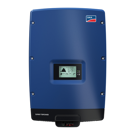
3 Product Description SMA Solar Technology AG 3.4 Display and LEDs The display and the LEDs of the inverter are located on the enclosure lid and indicate the operating state of the inverter. Figure 4: Design of the display Item Designation Explanation... -
Page 15: Communication
SMA Solar Technology AG 3 Product Description 3.5 Communication The inverter is equipped with a slot for connecting an SMA communication interface (e.g., RS485 or ® Bluetooth Wireless Technology). By means of the communication interface, the inverter can communicate with special SMA communication products (e.g. data logger, software) or other SMA inverters. -
Page 16: Display
• To view the display messages of the start-up phase again during regular operation, see Section 4.1 "Operating the Display", page 16. Display message Description Inverter device type SMC xxx Wrxxx Firmware version of the internal processors Configured country data set (example: VDE-AR-N4105-MP) Configuration of the SMA Power Balancer PowerBalancer (example: PowerGuard) PowerGuard SMC9-11TLRP-BA-en-30 User Manual... -
Page 17: Display Messages During Operation
SMA Solar Technology AG 4 Display 4.3 Display Messages during Operation When the inverter is in operation, the following messages alternate on the display. Each display message appears for five seconds, then the cycle starts again. Display message Description Current feed-in power and voltage of the PV array Current values for reactive power Qac and displacement power factor cos φ... -
Page 18: Led Signals
5 LED Signals SMA Solar Technology AG 5 LED Signals Designation Status Cause and corrective measures All LEDs glowing The inverter is initialising. flashing The start-up phase is beginning. If the DC voltage is very low in the start-up phase, all three LEDs go out and the start-up phase recommences. -
Page 19: Cleaning The Inverter
SMA Solar Technology AG 6 Cleaning the Inverter 6 Cleaning the Inverter • If the inverter is dirty, clean the enclosure lid, the display and the LEDs using only clear water and a cloth. User Manual SMC9-11TLRP-BA-en-30... -
Page 20: Glossary
A controlled reduction in performance, usually dependent on component temperatures SMA Power Balancer The SMA Power Balancer is a serial feature of the Sunny Mini Central. The SMA Power Balancer prevents the formation of an excessive unbalanced load during three-phase feed-in. This is enabled by connecting three Sunny Mini Centrals to a three-phase feed-in unit via a control cable. -
Page 21: Contact
SMA Solar Technology AG 8 Contact 8 Contact If you encounter technical problems, first contact your installer. The following information is required in order to provide you with the necessary assistance: • Inverter device type • Inverter serial number • Type and number of the PV modules connected •... - Page 23 Legal Provisions The information contained in this document is the property of SMA Solar Technology AG. Publishing its content, either partially or in full, requires the written permission of SMA Solar Technology AG. Any internal company copying of the document for the purposes of evaluating the product or its correct implementation is allowed and does not require permission.
Need help?
Do you have a question about the SUNNY MINI CENTRAL 9000TL and is the answer not in the manual?
Questions and answers