
Related Manuals for Baumer HUBNER BERLIN POG 10 R


Summary of Contents for Baumer HUBNER BERLIN POG 10 R
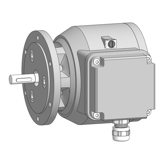
- Page 1 Montage- und Betriebsanleitung Mounting and operating instructions POG 10 R • POG 10 ET • POG 10 ETL Inkrementaler Drehgeber Incremental encoder...
-
Page 2: Table Of Contents
(nicht im Lieferumfang enthalten) Montage Schritt 1 Schritt 2 Schritt 3 Schritt 4 Maximal zulässige Montagefehler unter Verwendung der Baumer Hübner Federscheibenkupplung K 35 Hinweis bei Verwendung einer Klauen- kupplung (zum Beispiel „ROTEX®“) Kabelanschluss - Schritt 1 Kabelanschluss - Schritt 2 Montagehinweis... - Page 3 Step 1 Step 2 Step 3 Step 4 Maximum permissible mounting tolerance when the Baumer Hübner K 35 spring disk coupling is used Note when using a jaw-type coupling (for example “ROTEX®”) Cable connction - step 1 Cable connection - step 2...
-
Page 4: Allgemeine Hinweise
Gebrauchte Elektro- und Elektronikgeräte dürfen nicht im Hausmüll entsorgt werden. Das Produkt enthält wertvolle Rohstoffe, die recycelt werden können. Wenn immer möglich sollen Altgeräte lokal am entsprechenden Sammeldepot entsorgt werden. Im Bedarfsfall gibt Baumer den Kunden die Möglichkeit, Baumer-Produkte fachgerecht zu entsor- gen. Weitere Informationen siehe www.baumer.com. Achtung! Beschädigung des auf dem Gerät befindlichen Siegels... - Page 5 Whenever possible, waste electrical and electronic equipment should be disposed locally at the authorized collection point. If necessary, Baumer gives customers the opportunity to dispose of Baumer products profession- ally. For further information see www.baumer.com.
-
Page 6: Betrieb In Explosionsgefährdeten
Betrieb in explosionsgefährdeten Bereichen (nur bei Option ATEX) Betrieb in explosionsgefährdeten Bereichen (nur bei Option ATEX) Das Gerät entspricht den Bauvorschriften der Gerätekategorie 3 G, Gerätegruppe II (Ex-Atmo- sphäre Gas) und der Gerätekategorie 3 D, Gerätegruppe III (Ex-Atmosphäre Staub). Richtlinienkonformität gemäß 2014/34/EU. CE-Kennzeichnung: Kategorie 3 G: - Ex-Kennzeichnung:... - Page 7 Operation in potentially explosive environments (only with option ATEX) Operation in potentially explosive environments (only with option ATEX) The device meets the design requirements of equipment category 3 G, Equipment Group II (explosive gas atmosphere) and of equipment category 3 D, Equipment Group III (explosive dust atmosphere).
-
Page 8: Sicherheitshinweise
Sicherheitshinweise Sicherheitshinweise Verletzungsgefahr durch rotierende Wellen Haare und Kleidungsstücke können von rotierenden Wellen erfasst werden. • Vor allen Arbeiten alle Betriebsspannungen ausschalten und Maschinen stillsetzen. Zerstörungsgefahr durch elektrostatische Aufladung Die elektronischen Bauteile im Gerät sind empfindlich gegen hohe Spannungen. • Steckkontakte und elektronische Komponenten nicht berühren. •... - Page 9 Security indications Security indications Risk of injury due to rotating shafts Hair and clothes may become tangled in rotating shafts. • Before all work switch off all voltage supplies and ensure machinery is stationary. Risk of destruction due to electrostatic charge Electronic parts contained in the device are sensitive to high voltages. •...
-
Page 10: Vorbereitung
Vorbereitung / Preparation Vorbereitung Preparation Lieferumfang Scope of delivery Gehäuse Housing EURO-Flansch B10 EURO flange B10 Vollwelle mit Passfeder Solid shaft with key Klemmenkastendeckel Terminal box cover Kabelverschraubung M20x1,5 mm Cable gland M20x1.5 mm für Kabel ø5...13 mm (Option: M25 x 1,5 für for cable ø5...13 mm (Option: M25 x 1.5 for Kabel: ø... -
Page 11: Zur Montage Erforderlich
Vorbereitung / Preparation Zur Montage erforderlich Required for mounting (nicht im Lieferumfang enthalten) (not included in scope of delivery) Anbauvorrichtung, kundenspezifisch Installation fitting, customized Befestigungsschraube M6x16 mm, Fixing screw M6x16 mm, ISO 4017 ISO 4017 Federscheibenkupplung K 35, Spring disk coupling K 35, als Zubehör erhältlich, siehe Abschnitt 5.5. -
Page 12: Montage
Montage / Mounting Montage Mounting Am Beispiel vom POG 10 R / POG 10 ET. POG 10 R / POG 10 ET as example. Der POG 10 ETL ist um 180° gedreht. The POG 10 ETL is 180° rotated. Schritt 1 Step 1 Anzugsmoment: Tightening torque:... - Page 13 Montage / Mounting Schritt 3 Step 3 10 mm Schritt 4 Step 4 2.5 mm Anzugsmoment: Tightening torque: = 1.3 ±10 % Nm * Siehe Seite 8 See page 8 MB069b - 11117426 BAUMER_POG10-ET_DE_EN_202212_MI_11117426 (22A3)
-
Page 14: Maximal Zulässige Montagefehler Unter Verwendung Der Baumer Hübner Federscheibenkupplung K
Geräte mit Vollwelle sollten unter Verwen- Devices with a solid shaft should be dung der Baumer Hübner Federschei- driven through the Baumer Hübner K 35 benkupplung K 35 (Zubehör) angetrie- spring disk coupling (accessory), that ben werden, die sich ohne axialen Druck can be pushed onto the shaft without axial auf die Welle schieben lässt. -
Page 15: Hinweis Bei Verwendung Einer Klauen
Montage / Mounting Hinweis bei Verwendung einer Klauen- Note when using a jaw-type coupling kupplung (zum Beispiel „ROTEX®“) (for example “ROTEX®”) Eine falsche Montage der Klauenkupplung Incorrect mounting of the jaw-type cou- führt zur Beschädigung des Gerätes. pling can damage the device Mit einem Tiefenmessschieber die Use a depth gauge to find and observe korrekten Abstände (L, L1), siehe unten,... -
Page 16: Kabelanschluss - Schritt
Montage / Mounting Kabelanschluss - Schritt 1 Cable connction - step 1 TX 20 22 mm * Siehe Seite 7 See page 7 MB069b - 11117426 BAUMER_POG10-ET_DE_EN_202212_MI_11117426 (22A3) - Page 17 Montage / Mounting Kabelanschluss - Schritt 2 Cable connection - step 2 Zur Gewährleistung der angegebenen To ensure the specified protection of Schutzart sind nur geeignete Kabel- the device the correct cable diameter durchmesser zu verwenden. must be used. Vor der Montage des Klemmenkasten- Check that the seal of the terminal box deckels prüfen, ob die Klemmenka- is not damaged before mounting the...
-
Page 18: Montagehinweis
Montage / Mounting Montagehinweis Mounting instruction Wir empfehlen, das Gerät so zu It is recommended to mount the device montieren, dass der Kabelanschluss with cable connection facing down- keinem direkten Wassereintritt ward and being not exposed to water. ausgesetzt ist. MB069b - 11117426 BAUMER_POG10-ET_DE_EN_202212_MI_11117426 (22A3) -
Page 19: Abmessungen
Abmessungen / Dimensions Abmessungen Dimensions POG 10 R / POG 10 ET POG 10 R / POG 10 ET (73923) (73923) Drehrichtung positiv Positive rotating direction M20x1.5 (Option: M25 x 1.5) POG 10 ETL POG 10 ETL (73924) (73924) Drehrichtung positiv Positive rotating direction M20x1.5 (Option: M25 x 1.5) -
Page 20: Elektrischer Anschluss
Elektrischer Anschluss / Electrical connection Elektrischer Anschluss Electrical connection Beschreibung der Anschlüsse Terminal significance Betriebsspannung Voltage supply 0V ( ) Masseanschluss 0V ( ) Ground Erdungsanschluss Earth ground (Gehäuse) (housing) Ausgangssignal Output signal Kanal 1 channel 1 Ausgangssignal Output signal Kanal 1 invertiert channel 1 inverted Ausgangssignal... -
Page 21: Klemmenbelegung
There is no connection between Sensorkabel HEK 8 (Zubehör) Sensor cable HEK 8 (accessory) Es wird empfohlen, das Baumer Hübner Baumer Hübner sensor cable HEK 8 is Sensorkabel HEK 8 zu verwenden oder recommended. As a substitute a shielded ersatzweise ein geschirmtes, paarig ver- twisted pair cable should be used. -
Page 22: Demontage
Demontage / Dismounting Demontage Dismounting Am Beispiel vom POG 10 R / POG 10 ET. POG 10 R / POG 10 ET as example. Der POG 10 ETL ist um 180° gedreht. The POG 10 ETL is 180° rotated. Schritt 1 und 2 Step 1 and 2 TX 20 22 mm... -
Page 23: Schritt
Demontage / Dismounting Schritt 3 Step 3 10 mm 2.5 mm Schritt 4 Step 4 Schritt 5 Step 5 2.5 mm * Siehe Seite 8 See page 8 MB069b - 11117426 BAUMER_POG10-ET_DE_EN_202212_MI_11117426 (22A3) -
Page 24: Technische Daten
Technische Daten Technische Daten Technische Daten - elektrisch Betriebsspannung: 9...30 VDC (HTL-P, TTL - Version R) 5 VDC ±5 % (TTL) Betriebsstrom ohne Last: ≤100 mA Impulse pro Umdrehung: 300...5000 (je nach Bestellung) Phasenverschiebung: 90° ±20° Tastverhältnis: 40...60 % Referenzsignal: Nullimpuls, Breite 90°... - Page 25 Technical data Technical data Technical data - electrical ratings Voltage supply: 9...30 VDC (HTL-P, TTL - version R) 5 VDC ±5 % (TTL) Consumption w/o load: ≤100 mA Pulses per revolution: 300...5000 (as ordered) Phase shift: 90° ±20° Duty cycle: 40...60 % Reference signal: Zero pulse, width 90°...
- Page 26 Zubehör / Accessories Zubehör Accessories Federscheibenkupplung Spring disk coupling K 35 K 35 Sensorkabel für Drehgeber Sensor cable for encoders HEK 8 HEK 8 Werkzeugset: Tool kit: Bestellnummer 11068265 Order number 11068265 Digital-Konverter Digital converters HEAG 151 - HEAG 154 HEAG 151 - HEAG 154 LWL-Übertrager Fiber optic links...
- Page 27 Zubehör / Accessories MB069b - 11117426 BAUMER_POG10-ET_DE_EN_202212_MI_11117426 (22A3)
- Page 28 Baumer Germany GmbH & Co. KG Bodenseeallee 7 DE-78333 www.baumer.com Version: 73923, 73924 MB069b - 11117426 BAUMER_POG10-ET_DE_EN_202212_MI_11117426 (22A3-12.12.2022)
Need help?
Do you have a question about the HUBNER BERLIN POG 10 R and is the answer not in the manual?
Questions and answers