Table of Contents
Advertisement
Quick Links
Montage- und Betriebsanleitung
Mounting and operating instructions
Option G
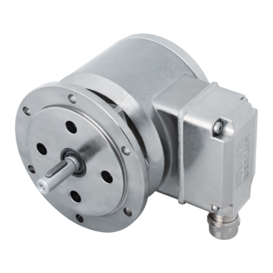
POG 11 (POG 11 G)
Inkrementaler Drehgeber (Zwillingsgeber)
Incremental encoder (Twin encoder)
Option Heizung
Option heating
Option G +
Option EMS: LED
Option EMS: LED
Option G +
Option M: redundant +
Option EMS: LED
Option M: redundant +
Option EMS: LED
Advertisement
Table of Contents

Related Manuals for Baumer POG 11


Summary of Contents for Baumer POG 11
- Page 1 Option G Option G + Option EMS: LED Option G + Option M: redundant + Option EMS: LED Option EMS: LED Option M: redundant + Option EMS: LED POG 11 (POG 11 G) Inkrementaler Drehgeber (Zwillingsgeber) Incremental encoder (Twin encoder)
-
Page 2: Table Of Contents
Schritt 7 und 8 - Klemmenkasten ......................5.11 Schritt 9 - Klemmenkasten ........................5.12 Schritt 10 - Klemmenkasten ........................Abmessungen ................................Standard ................................Option G: Zwillingsgeber POG 11 G ...................... Option Heizung ..............................Elektrischer Anschluss ............................Beschreibung der Anschlüsse ......................... Ausgangssignale ............................. Klemmenbelegung ............................ - Page 3 ..................................Step 3 ..................................Step 4 ..................................Maximum permissible mounting tolerance when the Baumer Hübner K 35 spring disk coupling is used ................ Note when using a jaw-type coupling (for example “ROTEX®”) ........... Mounting instruction ............................Step 5 - Terminal box ............................
-
Page 4: Allgemeine Hinweise
Information Empfehlung für die Gerätehandhabung Der inkrementale Drehgeber POG 11 (POG 11 G) ist ein opto-elektronisches Prä zi sions- messgerät, das mit Sorgfalt nur von technisch qualifiziertem Per sonal gehandhabt werden darf. Die zu erwartende Lebensdauer des Gerätes hängt von den Kugellagern ab, die mit einer Dauerschmierung ausgestattet sind. -
Page 5: General Notes
Information Recommendation for device handling The incremental encoder POG 11 (POG 11 G) is an opto electro nic precision measurement device which must be handled with care by skilled personnel only. The expected service life of the device depends on the ball bearings, which are equipped with a permanent lubrication. -
Page 6: Betrieb In Explosionsgefährdeten Bereichen
Betrieb in explosionsgefährdeten Bereichen Betrieb in explosionsgefährdeten Bereichen Das Gerät entspricht der Richtlinie 2014/34/EU für explosionsgefährdete Bereiche. Der Einsatz ist gemäß den Gerätekategorien 3 G (Ex-Atmosphäre Gas) und 3 D (Ex-Atmo- sphäre Staub) zulässig. Ausnahme: Versionen mit Heizung dürfen nicht in explosionsge- fährdeten Bereichen eingesetzt werden. -
Page 7: Operation In Potentially Explosive Environments
Operation in potentially explosive environments Operation in potentially explosive environments The device complies with the directive 2014/34/EU for potentionally explosive atmospheres. It can be used in accordance with equipment categories 3 G (explosive gas atmosphere) and 3 D (explosive dust atmosphere). Exception: Versions with heating must not be used in potentionally explosive atmospheres. -
Page 8: Sicherheitshinweise
Sicherheitshinweise Sicherheitshinweise Verletzungsgefahr durch rotierende Wellen Haare und Kleidungsstücke können von rotierenden Wellen erfasst werden. Vor allen Arbeiten alle Betriebsspannungen ausschalten und Maschinen stillsetzen. • Zerstörungsgefahr durch elektrostatische Aufladung Die elektronischen Bauteile im Gerät sind empfindlich gegen hohe Spannungen. Steckkontakte und elektronische Komponenten nicht berühren. •... -
Page 9: Security Indications
Security indications Security indications Risk of injury due to rotating shafts Hair and clothes may become tangled in rotating shafts. Before all work switch off all voltage supplies and ensure machinery is stationary. • Risk of destruction due to electrostatic charge Electronic parts contained in the device are sensitive to high voltages. -
Page 10: Vorbereitung
Option EMS: Status LED siehe Abschnitt 7.4. see section 7.4. Option Heizung, siehe Abschnitt 7.5. Option heating, see section 7.5. Option G: Zwillingsgeber POG 11 Option G: Twin encoder POG 11 Option M: Redundante Abtastung POG 11 Option M: Redundant sensing... -
Page 11: Zur Montage Erforderlich (Nicht Im Lieferumfang Enthalten)
Vorbereitung / Preparation Zur Montage erforderlich Required for mounting (nicht im Lieferumfang enthalten) (not included in scope of delivery) Anbauvorrichtung, kundenspezifisch Installation fitting, customized Befestigungsschrauben für Anbauvorrichtung Fixing screws for installation fitting ISO 4017, ISO 4017, M6x16 mm M6x16 mm Federscheibenkupplung K 35, Spring disk coupling K 35, als Zubehör erhältlich, siehe Abschnitt 5.5. -
Page 12: Montage
Montage / Mounting Montage Mounting In den Bildern am Beispiel vom POG 11 Stan- Pictures showing the standard POG 11 as example. dard. Gleiche Montageschritte bei allen anderen Same mounting steps for all versions. Versionen. Schritt 1 Step 1 Zul. Anzugsmoment Max. -
Page 13: Schritt 3
Montage / Mounting Schritt 3 Step 3 10 mm Schritt 4 Step 4 2.5 mm Zul. Anzugsmoment Max. tightening torque = 2-3 Nm * Siehe Seite 8 See page 8 MB070T1 - 11055673 Baumer_POG11-POG11G-T1_II_DE-EN (17A2) ... -
Page 14: Maximal Zulässige Montagefehler Unter Verwendung Der Baumer Hübner Federscheibenkupplung K 35
Montage / Mounting Maximal zulässige Montagefehler Maximum permissible mounting toler- unter Verwendung der Baumer Hübner ance when the Baumer Hübner K 35 Federscheibenkupplung K 35 spring disk coupling is used Geräte mit Vollwelle sollten unter Verwen- Devices with a solid shaft should be dung der Baumer Hübner Federschei-... -
Page 15: Hinweis Bei Verwendung Einer Klauenkupplung (Zum Beispiel „Rotex®")
Montage / Mounting Hinweis bei Verwendung einer Klauen- Note when using a jaw-type coupling kupplung (zum Beispiel „ROTEX®“) (for example “ROTEX®”) Eine falsche Montage der Klauenkupplung Incorrect mounting of the jaw-type cou- führt zur Beschädigung des Gerätes. pling can damage the device. Mit einem Tiefenmessschieber die Use a depth gauge to find and observe the korrekten Abstände (L, L1), siehe unten,... -
Page 16: Montagehinweis
Montage / Mounting Montagehinweis Mounting instruction Wir empfehlen, das Gerät so zu mon- It is recommended to mount the de- tieren, dass der Kabelanschluss kei- vice with cable connection facing nem direkten Wassereintritt ausge- downward and being not exposed to setzt ist. -
Page 17: Schritt 6 - Klemmenkasten
Montage / Mounting Schritt 6 - Klemmenkasten Step 6 - Terminal box TX 10 5.10 Schritt 7 und 8 - Klemmenkasten 5.10 Step 7 and 8 - Terminal box Ansicht siehe Abschnitt 7.3. Kabelschirm Cable shield View see section 7.3. ø5-13 mm * Siehe Seite 7 oder 8 See page 7 or 8... -
Page 18: Schritt 9 - Klemmenkasten
Montage / Mounting 5.11 Schritt 9 - Klemmenkasten 5.11 Step 9 - Terminal box D-SUB Buchse TX 10 zum Anschluss an Gerätegehäuse siehe Abschnitt 5.12. D-SUB connector (female) for connecting to device housing see section 5.12. 22 mm 5.12 Schritt 10 - Klemmenkasten 5.12 Step 10 - Terminal box Großer, um 180°... -
Page 19: Abmessungen
Abmessungen / Dimensions Abmessungen Dimensions Standard Standard (73862, 73868) (73862, 73868) Drehrichtung positiv Positive rotating direction 105.5 Option M: redundant Option EMS All dimensions in millimeters (unless otherwise stated) Option M + EMS MB070T1 - 11055673 Baumer_POG11-POG11G-T1_II_DE-EN (17A2) ... -
Page 20: Option G: Zwillingsgeber Pog 11 G
Abmessungen / Dimensions Option G: Zwillingsgeber POG 11 G Option G: Twin encoder POG 11 G (73863) (73863) Drehrichtung positiv Positive rotating direction 105.5 Option M: redundant Option EMS All dimensions in millimeters (unless otherwise stated) Option M + EMS MB070T1 - 11055673 ... -
Page 21: Option Heizung
Abmessungen / Dimensions Option Heizung Option heating (73860) (73860) Drehrichtung positiv Positive rotating direction Stromanschluss für Heizung, siehe auch Abschnitt 7.4. Power supply for heating, see also section 7.4. All dimensions in millimeters (unless otherwise stated) MB070T1 - 11055673 Baumer_POG11-POG11G-T1_II_DE-EN (17A2) ... -
Page 22: Elektrischer Anschluss
Elektrischer Anschluss / Electrical connection Elektrischer Anschluss Electrical connection Beschreibung der Anschlüsse Terminal significance Betriebsspannung (für das Gerät) +UB; + Voltage supply (for the device) Masseanschluss (für die Signale) ; ; GND; 0V Ground (for the signals) Erdungsanschluss (Gehäuse) Earth ground (housing) Ausgangssignal Kanal 1 K1;... -
Page 23: Klemmenbelegung
Elektrischer Anschluss / Electrical connection Klemmenbelegung Terminal assignment 7.3.1 Standard 7.3.1 Standard Max. 1,5 mm Ansicht X Max. AWG 16 Anschlussklemmen, siehe Abschnitt 5.10. View X Connecting terminal, see section 5.10. Zwischen besteht keine Verbindung. There is no connection between 7.3.2 Option EMS 7.3.2... -
Page 24: Option Ems (Enhanced Monitoring System): Status Led / Fehlerausgang
Elektrischer Anschluss / Electrical connection Option EMS (Enhanced Monitoring Option EMS (Enhanced Monitoring System): Status LED / Fehlerausgang System): Status LED / Error output Rotblinkend Signalfolge-, Nullimpuls- oder Flash light red Error of signal sequence, zero Impulszahlfehler (Fehlerausgang = pulse or pulses (Error output = HIGH-LOW-Wechsel) HIGH-LOW change) HIGH (5...30 V) -
Page 25: Option Heizung: Stromanschluss Für Heizung
Kabellänge / Cable length ~1 m Sensorkabel HEK 8 (Zubehör) Sensor cable HEK 8 (accessory) Es wird empfohlen, das Baumer Hübner Baumer Hübner sensor cable HEK 8 is Sensorkabel HEK 8 zu verwenden oder recommended. As a substitute a shielded ersatzweise ein geschirmtes, paarig ver- twisted pair cable should be used. -
Page 26: Demontage
Demontage / Dismounting Demontage Dismounting Schritt 1 Step 1 TX 10 TX 20 22 mm * Siehe Seite 7 oder 8 See page 7 or 8 MB070T1 - 11055673 Baumer_POG11-POG11G-T1_II_DE-EN (17A2) -
Page 27: Schritt 2
Demontage / Dismounting Schritt 2 Step 2 10 mm 2.5 mm Schritt 3 Step 3 Schritt 4 Step 4 2.5 mm * Siehe Seite 8 See page 8 MB070T1 - 11055673 Baumer_POG11-POG11G-T1_II_DE-EN (17A2) ... -
Page 28: Technische Daten
Montage / Mounting Technische Daten Technische Daten Technische Daten - elektrisch Betriebsspannung: 9...30 VDC (HTL-P, TTL - Version R) • 5 VDC ±5 % (TTL) Betriebsstrom ohne Last: ≤100 mA • Impulse pro Umdrehung: 300...5000 (je nach Bestellung) • Phasenverschiebung: 90°... -
Page 29: Technical Data
Technical data Technical data Technical data - electrical ratings Voltage supply: 9...30 VDC (HTL-P, TTL - version R) • 5 VDC ±5 % (TTL) Consumption w/o load: ≤100 mA • Pulses per revolution: 300...5000 (as ordered) • Phase shift: 90° ±20° • Duty cycle: 40...60 % •... -
Page 30: Eu-Konformitätserklärung
Signature/nom/fonction Baumer_HOGx_OGx_POGx_FOGx_HMI_DE-EN-FR_CoC_81201236.docm/kwe Baumer Hübner GmbH P.O. Box 126943 ∙ D-10609 Berlin ∙ Max-Dohrn-Str. 2+4 ∙ D-10589 Berlin Phone +49 (0)30 69003-0 ∙ Fax +49 (0)30 69003-104 ∙ info@baumerhuebner.com ∙ www.baumer.com Sitz der Gesellschaft / Registered Office: Berlin, Germany ∙ Geschäftsführer / Managing Director: Dr. Oliver Vietze, Dr. Johann Pohany Handelsregister / Commercial Registry: AG Charlottenburg HRB 96409 ∙... -
Page 31: Mit Heizung
Signature/nom/fonction Baumer_Geber_mit_Erdungsbürste_oder_Heizung_DE-EN-FR_CoC_81201634.docm/kwe Baumer Hübner GmbH P.O. Box 126943 ∙ D-10609 Berlin ∙ Max-Dohrn-Str. 2+4 ∙ D-10589 Berlin Phone +49 (0)30 69003-0 ∙ Fax +49 (0)30 69003-104 ∙ info@baumerhuebner.com ∙ www.baumer.com Sitz der Gesellschaft / Registered Office: Berlin, Germany ∙ Geschäftsführer / Managing Director: Dr. Oliver Vietze, Dr. Johann Pohany Handelsregister / Commercial Registry: AG Charlottenburg HRB 96409 ∙... -
Page 32: Zubehör
• HENQ 1100 HENQ 1100 * Siehe Abschnitt 4 See section 4 Baumer Hübner GmbH Originalsprache der Anleitung ist Deutsch. P.O. Box 12 69 43 · 10609 Berlin, Germany Technische Änderungen vorbehalten. Phone: +49 (0)30/69003-0 · Fax: +49 (0)30/69003-104 Original language of this instruction is German.
Need help?
Do you have a question about the POG 11 and is the answer not in the manual?
Questions and answers