
Related Manuals for Abloy DB001


Summary of Contents for Abloy DB001
- Page 1 ABLOY DB001, DB002 Swing door operators ® – Installation manual CSDB An ASSA ABLOY Group brand...
-
Page 2: Approvals
Ensure that entrapment between door and the surroundings is avoided. Ensure that the operator is suited for installation. Check temperature, humidity, door weights, etc. restriction, what is mentioned in this manual or other Abloy Oy material. ® Note! Instructions, design specifications and illustrations which are contained in this manual are not binding. -
Page 3: Table Of Contents
CONTENTS Approvals......................2 Revision.........................2 Content of delivery......................4 Technical specifications....................5 Operation......................6 Part idendification...................7 Installation......................8 Installing the mounting plate DB103.................9 Assembly of the operator and the standard arm DB104 to the closing side....10 Assembly of the operator and the sliding arm DB105 to the opening side....12 Assembly of the operator and the sliding arm DB105 to the closing side.....14 Electrical connections..................15 Adjustments......................16... -
Page 4: Content Of Delivery
CONTENT OF DELIVERY DB001 swing door operator EMSW - pushing - swing door operator, pushing - standard arm - 50 mm extension piece - 3 -position program switch - cover - extension piece for arm, reveal max. 230 mm DB002 swing door operator EMSW - pulling... -
Page 5: Technical Specifications
TECHNICAL SPECIFICATIONS ·Mains power supply: 230 VAC (-10 - +10 %), 50 Hz, fuse 10 A ·Power consumption: max 230 W ·Auxliary voltage : stabilized 24 VDC, 700 mA ·Motor Fuse: 6,3 AT ·Control unit fuse: 250 mAT ·Class of protection IP20 ·Dimensions: 716 mm x 110 mm x 110 mm (Length, Depth, Height) ·Weight: 11 kg ·Operation: -15...+30°C (in dry premises) -
Page 6: Operation
OPERATION The swing door operator works electro-hydraulically. It opens with an AC-motor that via a hydraulic unit and an arm system transmits the power to the door leaf. The closing power is from a coil spring. The movement of the door is controlled by limit switches and valve screws. -
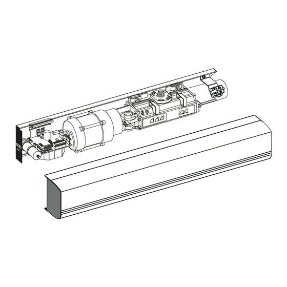
Page 7: Part Idendification
PART IDENTIFICATION Parts: 1. Base plate 2. Motor/Pump 3. Magnetic valve 4. Door closer 5. Drive shaft 6. Mains connection 7. Control unit 8. Program switch 9. End plate 10. Extension unit EXB-FI 11. Cover... -
Page 8: Installation
INSTALLATION Steps of installation - Preparing installation - Installing the mounting plate - Mounting the operator and the arm - Connecting the operator to mains - Commissioning - Testing - Connecting impulse devices Preparing installation - Check the proper function of the door - hinges - door clearance - Check the proper function of the lock... -
Page 9: Installing The Mounting Plate Db103
INSTALLATION Installing the mounting plate Operator is to be installed on the transom, with the main switch located towards the hinge. Use the mounting plate DB103 with the door operator ensuring the installation base is level and securely fixed to a flat surface. -
Page 10: Assembly Of The Operator And The Standard Arm Db104 To The Closing Side
Assembly of the operator and the standard arm DB104 to the closing side Adjustable hold open angle up to 120°. Mounting of the operator 6 pcs M6x12 Lenght of extension piece 2 – 17 No extension piece 0-105 17 – 37 20 mm (DB106) 50 mm (DB107) 37 –... - Page 11 Assembly of the operator and the standard arm DB104 to the closing side 90° 25 Nm 90°...
-
Page 12: Assembly Of The Operator And The Sliding Arm Db105 To The Opening Side
Assembly of the operator and the sliding arm DB105 to the opening side Mounting of the operator 6 pcs M6x12 Lenght of extension piece No extension piece 20 mm (DB106) 50 mm (DB107) 70 mm (DB108) Frame depth A, max 125 mm. - Page 13 Assembly of the operator and the sliding arm DB105 to the opening side Open the door in 90 degrees angle. 25 Nm...
-
Page 14: Assembly Of The Operator And The Sliding Arm Db105 To The Closing Side
Assembly of the operator and the sliding arm DB105 to closing side Mounting of the operator 6 pcs M6x12 Min. 54 Lenght of extension piece No extension piece 20 mm (DB106) 50 mm (DB107) 70 mm (DB108) Frame depth A, max 45 mm. -
Page 15: Electrical Connections
ELECTRICAL CONNECTIONS - Electrical connections should be made by a qualified electrician. - The power plug must have an easy access. - If a permanent connection is made unit must be equipped with an external switch providing all pole disconnection. - Keep the mains disconnected during installation. -
Page 16: Adjustments
ADJUSTMENTS Give a short opening impulse by strapping the impulse input and adjust if necessary as follows. Adjustment of the opening speed Adapt the high speed opening HSO, to the existing traffic situation. Turning clockwise decreases the speed. The low speed opening LSO, needs to be adjusted only if the door is extremely heavy. Turning clockwise decreases the speed. - Page 17 ADJUSTMENTS Closing side/PUSH = 70 N Opening side/PULL = 40 N 3 mm 5° 10 mm 3 mm 6 mm 5° Closing side/PUSH = 35 N Opening side/PULL = 20 N 2 mm...
-
Page 18: A Safe Door
A SAFE DOOR The safety of the door operator is controlled by basic adjustments; operator force, speeds, and hold open times. - The operator force is an important adjustment. A high value affects to the safety feature and also to its sensitivity. - High speeds increases the energy transferred in the door causing it not stop correctly. -
Page 19: Changing The Direction Of Rotation
CHANGING THE DIRECTION OF ROTATION The direction of rotation can changed by using tool DB110. 1. Washer and screw 2. Screw (4 pcs) 3. Bearing sleeve (2 pcs) 4. Tool DB110 5. Setting lines 1. Mount the washers and screws in the drive shaft, one from each side. 2. -
Page 20: Control Unit
CONTROL UNIT Internal connections Connection of EXB-FI extension unit Main supply Motor Limit switch open Capacitor Magnetic valve Home switch Limit switch open The limit switch indicates a fully open door and can be adjusted for opening angles up to 120º. - Page 21 External connections Hold open time Dip switches FS Key impulse Opening delay Hold open time Outer impulse Potentiometers Hold open time for outer impulse (Outer HOT) Hold open time can be adjusted 0 - 30 seconds. Opening delay Opening delay can be adjusted 0 - 3 seconds. When operator receives opening impulse, lockcase is opened first and door is opened after adusted delay time.
-
Page 22: Dip -Switches Fs
DIP -switches FS FS1 Kill input 1 2 3 4 5 6 7 8 Kill input not in use When kill is activated, the door will close immediately if not already closed. Hold open and low pass filter timers are reset. FS2 and FS3 Operation mode without program switch MVI impulse accepts a potential-free contact or 6-24 V AC/DC. - Page 23 FS6 Slave delay The slave unit has opening delay of 0,5 sec. The slave unit has a standard opening delay of 0,2 sec. FS7 Master/Slave Two pieces normal DB operators. Slave operator. Two pieces normal DB operators. Master operator. FS8 Push & Go A push on the door will, from closed position, start an automatic opening cycle if the programme selection is AUTO and remain open during the hold open time “Outer HOT”...
-
Page 24: Tb2 And Tb1
5 6 7 8 9 1011121314 When using kill input, connect 0 VDC. When kill is deactivated (0 VDC is connected), the door will act according to current input status. When kill is activated (0 VDC is disconnected), the door will close immediately if not already closed. Hold open and low pass filter timers are reset. -
Page 25: Connection Examples
CONNECTION EXAMPLES Program selector PS-3A Use this connection, if you want that lockcase is locked when program selector is in AUTO mode. Outer impulse is not in use. All impulse devices must connect to Key impulse (TB2 5 and 8). Opening delay is in use. - Page 26 CONNECTION EXAMPLES Program selector PS-3A When the diode is removed you will get following operation from DB swing door operator: AUTO: - The lockcase is electrically open. - Outer and Key impulse is in operation NOTE! Opening delay is not in operation. OPEN: - Door is open MANUAL:...
-
Page 27: Kill Input
Kill input 1 2 3 4 5 6 7 8 NOTE! FS1 = OFF 9 1011121314 5 6 7 8 When kill input opens: - Door closes - Hold open time resets - Key impulse will open the lock, but not the door. -
Page 28: Da061, Da062 And Da063 Microwave Motion Sensor
CONNECTION EXAMPLES DA061 and DA062 Microwave motion sensor 9 1011121314 5 6 7 8 DA063 Microwave motion sensor 5 6 7 8 9 1011121314 Program selector connection according page 25. -
Page 29: Da033 Elbow Switch And Da039 And Da049 Rotary Switch
CONNECTION EXAMPLES DA033 Elbow switch 5 6 7 8 9 1011121314 Program selector connection according page 25.. DA039 and DA049 rotary switch Black Yellow Add diode for example 1N4004 Diode is not included in the delivery. 5 6 7 8 9 1011121314 1 2 3 4 5 6 7 8 NOTE! -
Page 30: Extension Unit Exb-Fi
EXTENSION UNIT EXB-FI This extension unit is mounted on top of the control unit. 1. Connect the flat cable on the EXB-FI to the control unit. 2. Snap on the EXB-FI to the control unit. Extension unit EXB-FI is needed for bolt in information from lockcase and connecting safety sensor in opening side of the door. -
Page 31: Connection Examples Extension Unit Exb-Fi
CONNECTION EXAMPLES EXTENSION UNIT EXB-FI DA001 / DA002 Safety sensor in the opening side of the door 26 27 28 DB102 Jumper setting (DARK ON) for DA001 and DA002. ° ° ° Blanking switch will prevent detection of wall. Connect the switch in parallel with DA001/DA002 output. -
Page 32: Da001 / Da002 Safety Sensor In The Closing Side Of The Door
CONNECTION EXAMPLES EXTENSION UNIT EXB-FI DA001 / DA002 Safety sensor in the closing side of the door 26 27 28 Jumper setting (DARK ON) for DA001 and DA002. -
Page 33: Connection Examples Control Unit And Extension Unit Exb-Fi
CONNECTION EXAMPLES CONTROL UNIT AND EXTENSION UNIT EXB-FI Electric locks EL402, EL404, EL502 CONTROL UNIT EXTENSION UNIT EXB-FI 26 27 28 1 2 3 4 5 6 7 8 5 6 7 8 9 1011121314 100µF Green NOTE! FS4 = ON FS5 = ON Blue Black... -
Page 34: Program Switch, Motor Lock And Safety Sensor In The Opening Side Of The Door
CONNECTION EXAMPLES CONTROL UNIT AND EXTENSION UNIT EXB-FI Program switch, motor lock and safety sensor in the opening side of the door... -
Page 35: Fire Door Use
CONNECTION EXAMPLES CONTROL UNIT AND EXTENSION UNIT EXB-FI Fire door use... -
Page 36: Connection Of Double Doors
CONNECTION OF DOUBLE DOORS Control unit for passive door Main power Motor Capacitor Magnetic valve Limit switch open Connection Passive door Active door... - Page 37 CONNECTION OF DOUBLE DOORS Active door Passive door NOTE! FS1 = ON FS7 = ON 1 2 3 4 5 6 9 1011121314 5 6 7 8 Adjust opening delay and Key hold open time to 0 second. All impulse devices must be connected to active door control unit. With this connection it is possible to feed more current to impulse devices.
-
Page 38: Coordinator Db109
COORDINATOR DB109 Coordinator ensures that rebated doors are closing in right sequence. Parts: Plastic hose Lever bracket Return spring Wire wheel Balance spring Hook bracket... -
Page 39: Closing Side
INSTALLATION OF COORDINATOR DB109 Closing side: The brackets 1 and 2 are to be mounted to the pump flange on the active door operator and the wire wheel 3 to the drive shaft on the passive door operator. Note! If the active and passive doors are interchanged, the brackets are to be fitted to the underside of the pump flange. -
Page 40: Opening Side
INSTALLATION OF COORDINATOR DB109 Opening side The brackets 1 and 2 are to be mounted to the pump flange on the active door operator and the wire wheel 3 to the drive shaft on the passive door operator. Note! If the active and passive doors are interchanged, the brackets are to be fitted to the underside of the pump flange. -
Page 41: Push&Go Db116
PUSH&GO DB116 Control unit 5 6 7 8 9 1011121314 Black Green A – A Remove screw before installing Alternative PC-board fixing hole depending on mounting side and if "Push" or "Pull" PC-board fixing and adjustment screw Hall switch B – B Magnet a°... -
Page 42: Troubleshooting
TROUBLESHOOTING FAULT POSSIBLE REASON EXPLANATION The door does not open Change setting Program selector is set to OFF Motor power is missing Check motor cable - The motor does not Mains power is missing Check power, replace fuse start Impulse device is broken Check the impulse device Arm system has come loose Readjust pre-tension and... -
Page 43: Accessories And Spare Parts
ACCESSORIES AND SPARE PARTS KOODI HUOM. NIMI Tool kit to change DB110 rotation direction Safety sensor on the opening side of the door, Limit switch DB102 door closed information Mounting plate DB103 Pushing arm DB104 Sliding arm DB105 Extension piece DB106 20mm Extension piece... - Page 44 ACCESSORIES AND SPARE PARTS CODE NOTE. NAME DB109 Coordinator Control unit 5742099 CSDB + EXB-FI Control unit for 5742069 passive door 5742094 Hydraulic unit...
- Page 48 An ASSA ABLOY Group brand Abloy Oy is one of the leading manufacturers of locks, locking systems and architectural hardware and the world’s leading developer of products in the field of electromechanical locking technology. ASSA ABLOY is the global leader in door opening solutions, dedicated to satisfying end-user needs for security, safety and convenience.
Need help?
Do you have a question about the DB001 and is the answer not in the manual?
Questions and answers