Sign In
Upload
Download
Table of Contents
Contents
Add to my manuals
Delete from my manuals
Share
URL of this page:
HTML Link:
Bookmark this page
Add
Manual will be automatically added to "My Manuals"
Print this page
×
Bookmark added
×
Added to my manuals
Manuals
Brands
Bosch Manuals
Horn
LHN-UC15L-SIP
User manual
Bosch LHN-UC15L-SIP User Manual
Hide thumbs
1
2
Table Of Contents
3
4
5
6
7
8
9
10
11
12
13
14
15
16
17
18
19
20
21
22
23
24
25
26
27
28
29
30
31
32
33
34
35
36
37
38
39
40
41
42
43
44
45
46
47
48
49
50
51
52
page
of
52
Go
/
52
Contents
Table of Contents
Bookmarks
Table of Contents
Table of Contents
Safety
Safety Information
Disposal Instructions
FCC Statement - Wired Class B Digital Device (Unintentional Radiator)
FCC Suppliers Declaration of Conformity
Installation
LHN-UC15L-SIP or LHN-UC15W-SIP IP Horn Loudspeaker
Considerations
Mounting
Connections
Microphone
Physical Reset Button
AMN-P15-SIP IP Amplifier Module
Considerations
Mounting
Connections
Physical Reset Button
Getting Started
Download and Update Firmware
IP Address Detection
Logon with the Web Browser
Web-GUI Configuration
Overview
Generic Settings
Users
Sip
SIP Settings
SIP Accounts
Audio
Basic Audio Settings
Advanced Audio Settings
Messages
Rules
Name and Priority
Trigger Settings
Action Settings
Certificates
Security
Maintenance
Device Tests
User Interface Settings
General Purpose Inputs and Outputs
Miscellaneous
Logging
Logout
Https Rest Api
Direct Bosch Camera Integration Via ATSL
Technical Data
Advertisement
Quick Links
1
Connections
2
Download and Update Firmware
3
Ip Address Detection
Download this manual
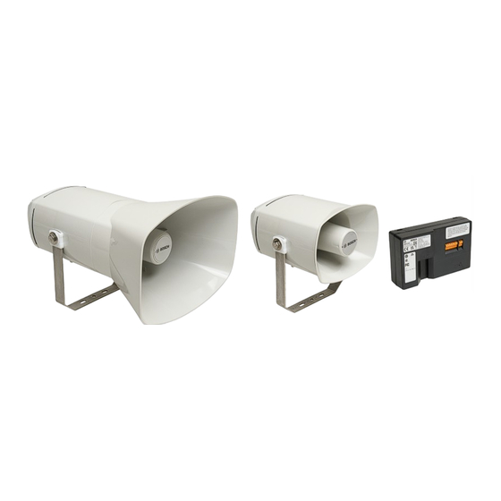
LHN‑UC15L‑SIP | LHN‑UC15W‑SIP |
AMN‑P15‑SIP
en
User manual
Table of
Contents
Previous
Page
Next
Page
1
2
3
4
5
Advertisement
Table of Contents
Need help?
Do you have a question about the LHN-UC15L-SIP and is the answer not in the manual?
Ask a question
Questions and answers
Related Manuals for Bosch LHN-UC15L-SIP
Horn Bosch Security Systems LBC 3438/00 Installation Manual
Horn loudspeaker (4 pages)
Horn Bosch LBC 3481 12 Installation And User Instructions Manual
Horn loudspeakers (6 pages)
Horn Bosch LBC 3428 Installation Manual
Horn loudspeaker (4 pages)
Horn Bosch LHN-UC15W-SIP User Manual
(52 pages)
Horn Bosch AMN-P15-SIP User Manual
(52 pages)
Horn Bosch STH‑15S Series Specifications
Supervised horn loudspeakers (2 pages)
Horn Bosch SUPERNOVA M99 Manual
With m99 pro (19 pages)
This manual is also suitable for:
Lhn-uc15w-sip
Amn-p15-sip
F.01u.389.835
F.01u.389.865
F.01u.389.866
Table of Contents
Print
Rename the bookmark
Delete bookmark?
Delete from my manuals?
Login
Sign In
OR
Sign in with Facebook
Sign in with Google
Upload manual
Upload from disk
Upload from URL


Need help?
Do you have a question about the LHN-UC15L-SIP and is the answer not in the manual?
Questions and answers