Advertisement
Quick Links
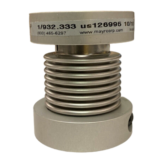
Installation and Operational Instructions for
®
smartflex
-couplings Types 932.3_3 and 932.433
Please read the Installation and Operational Instructions carefully
Ignoring these Instructions may lead to malfunctions or to coupling failure, resulting in damage to other parts.
Contents:
Page 1:
- Contents
- Declaration of Conformity
- Safety Regulations
- Safety and Guideline Signs
Page 2:
- Coupling Variants
- Parts List
- Table 1: Technical Data
- Table 2: Clamping Connection Bores and
Corresponding Transmittable
Torques TR [Nm]
- Table 3: Preferred Bores
Page 3:
- Design
- Function
- State of Delivery
- Installation Guidelines for Shaft Ends
- Adapting to the Shaft Diameter
- Shaft Requirements
- Temperature Resistance
- Installation Position
Declaration of Conformity
A conformity evaluation for the applicable EU directives has been carried out for this product.
The conformity evaluation is set out in writing in a separate document and can be requested if required.
It is forbidden to start use of the product until the machine or system into which it should be built is operating in accordance with all appli-
cable EU directives.
Without a conformity evaluation, this product is not suitable for use in areas where there is a high danger of explosion.
This statement is based on the ATEX directive.
Safety Regulations
These Installation and Operational Instructions (I+O) are part of the coupling delivery.
Please keep them handy and near to the coupling at all times.
Danger!
This warning applies if:
the shaft couplings are modified.
the relevant standards for safety and / or installation conditions are ignored.
User-implemented Protective Measures
Cover moving parts to protect against seizure, dust or foreign body impact.
To prevent injury or damage, only professionals and suitably qualified personnel should work on the devices,
following the relevant standards and directives. Please read the Installation and Operational Instructions
carefully before installing and operating the device.
Safety and Guideline Signs
Danger!
Danger of injury to personnel and damage
to machines.
20/08/2008 TK/NV/SU/GC
Page 1 of 6
and follow them accordingly.
These Safety Regulations are user hints only and may not be complete!
Chr. Mayr GmbH + Co. KG
Eichenstraße 1
87665 Mauerstetten
Germany
Page 4:
- Coupling Installation
- Important Installation Guidelines
- Installation Types 932.333 and 932.433
- Installation Type 932.343
- Coupling Installation onto Cylindrical Shaft
- Coupling Installation onto Conical Shaft
- Coupling Installation into a Bell-Type Housing
Page 5:
- Coupling Dimensioning
- Diagram 1 (Dimensioning Sizes 0 to 2)
- Diagram 2 (Dimensioning Sizes 3 to 5)
- Table 4: Temperature Factors
- Permitted Shaft Misalignments
Page 6:
- Maintenance
- Disposal
- Malfunctions / Breakdowns
Please Observe!
According to German notation, decimal
points in this document are represented
with a comma (e.g. 0,5 instead of 0.5).
Please Observe!
Guidelines on important points.
Tel.: 08341 / 804-241
Fax: 08341 / 804-422
http://www.mayr.de
eMail:
info@mayr.de
(B.9.8.GB)
Advertisement

Related Manuals for Mayr Smartflex 932.3 3 Series


Summary of Contents for Mayr Smartflex 932.3 3 Series
- Page 1 Danger! Please Observe! Danger of injury to personnel and damage Guidelines on important points. to machines. 20/08/2008 TK/NV/SU/GC Chr. Mayr GmbH + Co. KG Tel.: 08341 / 804-241 Eichenstraße 1 Fax: 08341 / 804-422 87665 Mauerstetten http://www.mayr.de Page 1 of 6...
- Page 2 30, 32, 35, 36, 38, 40, 42, 45, 48, 50, 55, 60, 62 40, 42, 45, 48, 50, 55, 60, 62, 65, 70, 75, 80, 85 20/08/2008 TK/NV/SU/GC Chr. Mayr GmbH + Co. KG Tel.: 08341 / 804-241 Eichenstraße 1...
- Page 3 ) Installation Position: Can be defined by the user. Cone 1:10 (28) Fig. 3 20/08/2008 TK/NV/SU/GC Chr. Mayr GmbH + Co. KG Tel.: 08341 / 804-241 Eichenstraße 1 Fax: 08341 / 804-422 87665 Mauerstetten http://www.mayr.de Page 3 of 6...
- Page 4 (5) are aligned (see Fig. 5). 9. Tighten the cap screws (4). The screw tightening torques (see Table 1) must be observed. Fig. 8 20/08/2008 TK/NV/SU/GC Chr. Mayr GmbH + Co. KG Tel.: 08341 / 804-241 Eichenstraße 1 Fax: 08341 / 804-422 87665 Mauerstetten http://www.mayr.de...
- Page 5 For drives in machine tools (servo motors), we recommend the fB values of 1,5. Fig. 10 ∆ K [%] Axial displacement 20/08/2008 TK/NV/SU/GC Chr. Mayr GmbH + Co. KG Tel.: 08341 / 804-241 Eichenstraße 1 Fax: 08341 / 804-422 87665 Mauerstetten http://www.mayr.de...
- Page 6 ® mayr , or for damage resulting from the use of these products. 20/08/2008 TK/NV/SU/GC Chr. Mayr GmbH + Co. KG Tel.: 08341 / 804-241 Eichenstraße 1 Fax: 08341 / 804-422 87665 Mauerstetten http://www.mayr.de...
Need help?
Do you have a question about the Smartflex 932.3 3 Series and is the answer not in the manual?
Questions and answers