
Related Manuals for Caple Tela TEL900


Summary of Contents for Caple Tela TEL900
- Page 1 Te l a I s l a n d H o o d I n s t r u c t i o n M a n u a l T EL9 00 Contact Caple on 0117 938 7420 for spare parts or www.caple.co.uk...
-
Page 2: Table Of Contents
C O N T E N T S Safety Instructions Environmental Protection Installation TEL900/SHELF Maximum Load Control Panel Timing Lighting Cleaning and Maintenance After Sales Caple Contact Details Instruction manual TEL900 Please keep this instruction manual for future reference... -
Page 3: Safety Instructions
S A F E T Y I N S T R U C T I O N S W A R N I N G - The cooking surface and the inferior part of the cooker hood must be at a minimum distance of 65 cm. - The appliance is not intended for use by young children or infirm persons without supervision. - Page 4 - If the appliance is equipped with a power cord and a plug, it shall be placed in such a way that the plug can be reached easily. - The use of materials which can burst into flames should be avoided in close proximity of the appliance. When frying, please pay particular attention to fire risk due to oil and grease.
- Page 5 - Children under 8 years of age must be kept away from the cooker hood unless they are constantly supervised. - Children 8 years and older may only use the cooker hood unsupervised if they have been shown how to use it safely and recognise and understand the consequences of incorrect operation.
- Page 6 A P P R O P R I A T E U S E : - This appliance is intended to be used in household and similar applications such as: › Staff kitchen areas in shops, offices and other working environments. ›...
-
Page 7: Environmental Protection
Registration can also be completed online by visiting www.caple.co.uk. Ensure you keep your warranty card safe, you may need to show it to Caple Service together with proof of purchase. If you fail to show your warranty card you will incur all repair charges. - Page 8 This appliance conforms to all current and applicable energy regulations. To view the Technical Fiche that supports the energy labelling data, please visit the product page on our website www.caple.co.uk. Instruction manual TEL900 Please keep this instruction manual for future reference...
-
Page 9: Installation
I N S T A L L A T I O N This appliance can be used in recirculation mode only. In recirculation mode the air and fumes conveyed by the appliance are cleaned by both a grease filter and an active charcoal filter, and then released back into the room. - Page 10 W H A T ’ S I N T H E B O X W H AT ’ S I N T H E B OX (x2) = S (x2) = R (x4) = Q ( x1) = P (x2) = N (x2) = M (x4) = L 4 x 16 (x12) = I...
- Page 11 Start by removing the product from the packaging and lay it on a suitable surface such as a soft Start by removing the product from the packaging and lay it on a suitable surface such Start by removing the product from the packaging and lay it on a suitable surface such material to protect the surface of the hood.
- Page 12 3. Fix the brackets (S) to the ceiling using the plugs (A) and screws (B) supplied. 3. Fix the brackets (S) to the ceiling using the plugs (A) and screws (B) supplied. 3. Fix the brackets (S) to the ceiling using the plugs (A) and screws (B) supplied. 4.
- Page 13 > Add the clips as a further safety precaution to lock the cables in position (Fig.7). > Add the clips as a further safety precaution to lock the cables in position (Fig.7). Fig.7. > Put the hood near the ceiling and hook the plate to the screws previously installed (Fig.8A). >...
- Page 14 > The grease filter must be positioned by orienting > The grease filter must be positioned by orienting the dedicated opening near the speed indicator the dedicated opening near the speed indicator (Fig.17). In case the ceramic cover of the body is (Fig.17).
- Page 15 6. Fix the frame to the hood using the screws (H) provided. 6. Fix the frame to the hood using the screws (H) provided. 6. Fix the frame to the hood using the screws (H) provided. > The grease filter must be positioned by orienting the dedicated opening near the speed indicator (Fig.17).
- Page 16 8. If necessary, with a suitable metal saw carefully cut down the upper legs (Q) to 8. If necessary, with a suitable metal saw carefully cut down the upper legs (Q) to the > The grease filter must be positioned by orienting the required size.
- Page 17 12. Fix the upper legs (Q) to the previously installed ceiling brackets (S) using the fixings (E +F) 12. Fix the upper legs (Q) to the previously installed ceiling brackets (S) using 12. Fix the upper legs (Q) to the previously installed ceiling brackets (S) using >...
- Page 18 14. Push the electrical cable from the top of the structure (L) into the bottom of 14. Push the electrical cable from the top of the structure (L) into the bottom of the upper leg 14. Push the electrical cable from the top of the structure (L) into the bottom of the upper leg (Q).
- Page 19 1. 17. Fix the covers (R) to the ceiling brackets (S) using the fixing (I) supplied. 17. Fix the covers (R) to the ceiling brackets (S) using the fixing (I) supplied. 17. Fix the covers (R) to the ceiling brackets (S) using the fixing (I) supplied. >...
-
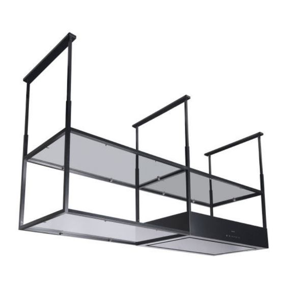
Page 20: Tel900/Shelf
T E L 9 0 0 / S H E L F T E L 9 0 0 / S H E L F > The grease filter must be positioned by orienting The Tela shelf unit is available to purchase separately and can be installed either side of the The Tela shelf unit is available to purchase separately and can be installed either side of the the dedicated opening near the speed indicator hood. - Page 21 I N S TA L L AT I O N I N S T A L L A T I O N S T A L L A T I O N IMPORTANT: I M P O R TA N T: The TEL900/SHELF is to be installed at the same time as t he TEL900 extractor.
- Page 22 > The grease filter must be positioned by orienting the dedicated opening near the speed indicator (Fig.17). In case the ceramic cover of the body is > The grease filter must be positioned by orienting not perfectly flat or parallel to the body, it is the dedicated opening near the speed indicator possible to make an adjustment after installation.
- Page 23 4. Assemble the hood frame as shown in the following images. 4. Assemble the hood frame as shown in the following images. Instruction manual TEL900 Please keep this instruction manual for future reference...
- Page 24 � __ _ ..___ _ _ __ _ __ ... 24 Instruction manual TEL900 Please keep this instruction manual for future reference...
- Page 25 Instruction manual TEL900 Please keep this instruction manual for future reference...
- Page 26 5. Thread the power cable through the frame, then place the frame onto the hood. 5. Thread the power cable through the frame, then place the frame onto the hood. 5. Thread the power cable through the frame, then place the frame onto the hood. 6.
- Page 27 7. Assemble the shelf unit frame as shown in the following images. 7. Assemble the shelf unit frame as shown in the following images. Instruction manual TEL900 Please keep this instruction manual for future reference...
- Page 28 28 Instruction manual TEL900 Please keep this instruction manual for future reference...
- Page 29 Instruction manual TEL900 Please keep this instruction manual for future reference...
- Page 30 30 Instruction manual TEL900 Please keep this instruction manual for future reference...
- Page 31 8. Fix the shelf unit frame to the hood using the screws (H) provided. 8. Fix the shelf unit frame to the hood using the screws (H) provided. 8. Fix the shelf unit frame to the hood using the screws (H) provided. Instruction manual TEL900 Please keep this instruction manual for future reference...
- Page 32 9. Temporarily place the upper legs (Q) onto the frame and check that when 9. Temporarily place the upper legs (Q) onto the frame and check that when installed, the installed, the hood will be the required distance shown below. hood will be the required distance shown below.
- Page 33 11. Place the upper legs (Q) onto the structure. 11. Place the upper legs (Q) onto the structure. 11. Place the upper legs (Q) onto the structure. 12. Once aligned correctly, mark the location on the upper legs (Q). 12. Once aligned correctly, mark the location on the upper legs (Q). 12.
- Page 34 14. Fix the upper legs (Q) to the previously installed ceiling brackets (S) using the fixings (E+F) 14. Fix the upper legs (Q) to the previously installed ceiling brackets (S) using the 14. Fix the upper legs (Q) to the previously installed ceiling brackets (S) using the supplied.
- Page 35 16. Push the electrical cable from the top of the structure into the bottom of the upper 16. Push the electrical cable from the top of the structure into the bottom of the upper leg (Q). 16. Push the electrical cable from the top of the structure into the bottom of the upper leg (Q). leg (Q).
- Page 36 19. Fix the covers (R) to the ceiling brackets (S) using the fixing (I) supplied. 19. Fix the covers (R) to the ceiling brackets (S) using the fixing (I) supplied. 19. Fix the covers (R) to the ceiling brackets (S) using the fixing (I) supplied. 19.
-
Page 37: Maximum Load
M A X I M U M L O A D I M P O R TA N T MAXIMUM LOAD Make sure the total weight placed on top of the shelving does not exceed those shown in the following image. IMPORTANT Make sure the total weight placed on top of the shelving does not exceed those shown in the following image. -
Page 38: Control Panel
C O N T R O L PA N E L A. ANTI-CONDENSATION SYSTEM switch on/off This is an innovative anti-condensation system, based on thermal resistances inside the glass panel. By heating the surface in contact with the the induction hob, this system reduced condensation and helps prevent water drops developing and falling on the hob. -
Page 39: Timing
T I M I N G › This product is equipped with intelligent electronics which include a timer device for speed controls when the air capacity exceeds 650m³/h. Internal motor models, with maximum air capacity higher than 650m³/h, are equipped with a timer device that automatically switches the speed from 4th to 3rd speed, after 5 minutes operation. -
Page 40: Lighting
L I G H T I N G D I M M A B L E L I G H T S F U N C T I O N This function provides for lights dimmability, ranging from 20% to 100%, by continuously pressing the light key on the control panel. -
Page 41: Cleaning And Maintenance
To purchase a replacement charcoal filter The active charcoal filter can be washed and re-used for up to a maximum 3 years. We (CAP86CF) please visit www.caple.co.uk. To clean the charcoal filters, wash by hand with warm water or in the dishwasher at the highest recommend that these are replaced after this period. - Page 42 The active charcoal filter can be washed and re-used for up to a maximum 3 years. We recommend that these are replaced after this period. To purchase a replacement charcoal filter (CAP86CF) please visit www.caple.co.uk 42 Instruction manual TEL900 Please keep this instruction manual for future reference...
- Page 43 This product contains a light source of energy efficiency class F. The LED light must be replaced by an authorised engineer or similar only. For more information, please contact Caple service - 0117 938 7420 or service@caple.co.uk Unplug the unit from the power supply before starting the process.
-
Page 44: After Sales
Any maintenance operation on your appliance should be carried out by: › Either your retailer; › Or another Caple approved engineer or similar qualified person. If a problem still persists and further assistance is required, please contact our Caple after sales team on: T - 0117 938 7420 E - service@caple.co.uk... - Page 45 N O T E S Instruction manual TEL900 Please keep this instruction manual for future reference...
- Page 46 N O T E S 46 Instruction manual TEL900 Please keep this instruction manual for future reference...
- Page 47 N O T E S Instruction manual TEL900 Please keep this instruction manual for future reference...
-
Page 48: Caple Contact Details
Caple Service Fourth Way Avonmouth T: 0117 938 1900 Bristol E: service@caple.co.uk BS11 8DW www.caple.co.uk...
Need help?
Do you have a question about the Tela TEL900 and is the answer not in the manual?
Questions and answers