Nortel BCM50 Installation And Configuration Manual
Nortel bcm50: user guide
Hide thumbs
Also See for BCM50:
- Configuration manual (568 pages) ,
- Installation and maintenance manual (335 pages) ,
- Administration manual (191 pages)

Subscribe to Our Youtube Channel
Related Manuals for Nortel BCM50


Summary of Contents for Nortel BCM50
- Page 1 BCM50 First Time Installation and Configuration Guide Part No. N0027149 01 08 April 2005...
- Page 2 Nortel Networks. Trademarks *Nortel, Nortel (Logo), the Globemark, and This is the way, This is Nortel (Design mark) are trademarks of Nortel Networks. *Microsoft, MS, MS-DOS, Windows, and Windows NT are registered trademarks of Microsoft Corporation.
-
Page 3: Software License
THE TERMS OF THIS LICENSE. IF YOU DO NOT AGREE TO THE TERMS OF THIS LICENSE, RETURN THE UNUSED SOFTWARE AND THE ASSOCIATED DOCUMENTATION TO NORTEL NETWORKS THROUGH A NORTEL NETWORKS AUTHORIZED DISTRIBUTOR WITHIN FIVE (5) DAYS OF YOUR ACQUISITION OF THE SOFTWARE FOR A REFUND. - Page 4 License. If NORTEL NETWORKS (i) claims a material breach of this License, and (ii) provides written notice of such claimed material breach to CUSTOMER and (iii) observes that such claimed material breach remains uncorrected and/or unmitigated more than thirty (30) days following CUSTOMER’s receipt of written notice specifying in reasonable detail...
-
Page 5: Default Ip Addresses
Router IP address 10.10.11.1 192.168.1.2 192.168.1.1 User ID | User Name nnadmin SETNNA (738662) SETNNA (738662) – nnadmin – BCM50 First Time Installation and Configuration Guide Subnet mask 255.255.255.252 255.255.255.0 255.255.255.0 Password PlsChgMe! CONFIG (266344) CONFIG (266344) CONFIG (266344) PlsChgMe! - Page 6 N0027149 01 N0027149 01...
-
Page 7: Table Of Contents
Task List Installing the BCM50 hardware ........17 To install a BCM50 unit ...17... - Page 8 Task List N0027149 01 N0027149 01...
- Page 9 Chapter 2 Installing the BCM50 hardware........17 Installing a BCM50, BCM50a, or BCM50e main unit .
- Page 10 Contents N0027149 01 N0027149 01...
-
Page 11: Getting Started With Bcm50
• enables you to create and provide telephony applications for use in a business environment This guide leads an installer through initial installation and configuration of a new BCM50 system. This guide assumes that: •... -
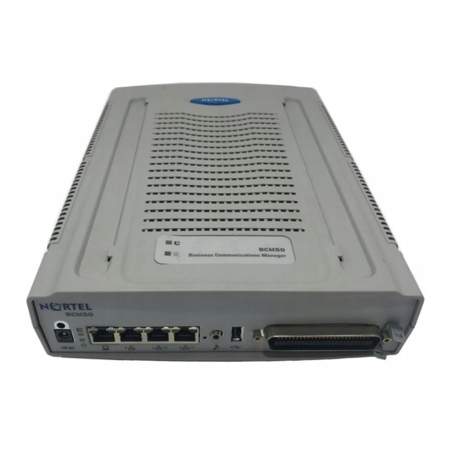
Page 12: Main Units
4 analog station ports, and 4 connections for auxiliary equipment (auxiliary ringer, page relay, page output, and music source). The BCM50 main unit does not have a router, but it does have 4 LAN ports: one is the OAM port for technicians, and the other three are for basic LAN connectivity. - Page 13 Figure 1 BCM50 main unit ports and connectors (port 1) (port 0) Retention clip mounting hole Power Figure 2 BCM50a main unit ports and connectors Retention clip mounting hole Power (port 0) (port 1) Figure 3 BCM50e main unit ports and connectors...
-
Page 14: Expansion Unit And Media Bay Modules (Mbm)
Chapter 1 Getting started with BCM50 Expansion unit and media bay modules (MBM) In addition to a main unit, the BCM50 system can have up to two expansion units. An expansion unit connects to the main unit and provides additional functionality. Refer to expansion unit port locations. - Page 15 This module also allows you to download new firmware. BCM50 First Time Installation and Configuration Guide Special notes Can connect to one of four types of lines: TI, North American PRI, ETSI ISDN (E1), and European PRI (E1).
-
Page 16: Additional Bcm50 Hardware
Wallmount bracket A bracket designed for mounting a BCM50 unit (main unit or expansion unit) to a wall. An optional wiring field card (WFC), which provides RJ-45 connectors for all main unit trunk and station interfaces, is available with the wallmount bracket. -
Page 17: Installing The Bcm50 Hardware
BCM50 First Time Installation and Configuration Guide (N0027149) To install a BCM50 unit The BCM50 can be installed on a rack, on a wall, or on a desktop. Refer to the BCM50 Installation and Maintenance Guide (N027152) for more details on the installation options. -
Page 18: To Verify The Media Bay Module (Mbm) Switches
Other screws can damage the unit. Review these messages when stacking BCM50 units on top of one another: Caution: Do not attempt to install a BCM50 unit on top of a wallmounted unit. Wallmounted units must be installed directly on the wall using a wallmount bracket for each unit. -
Page 19: To Install An Mbm In An Expansion Unit
ON — Enhanced mode (firmware downloading supported) OFF — if you want the GASM8 to download the firmware when the firmware version in the BCM50 is different than the version in the GASM8 (default) ON — if you want the GASM8 to download the firmware whenever there is a cold start of the BCM50 OFF —... -
Page 20: To Connect The Power Supply Without A Ups
• “To connect the power supply without a UPS” • “To connect the power supply using a UPS” – refer to the BCM50 Installation and Maintenance Guide (N027152). To connect the power supply without a UPS Rotate the retention clip so the power outlet is open. -
Page 21: Connecting The Telephony Connector
Connecting the telephony connector Note: You can use the wiring field card (WFC) or rackmount patch panel to simplify the connections of the telephony connector to the BCM50. Refer to the BCM50 Installation and Maintenance Guide (N027152) for more information. - Page 22 Chapter 2 Installing the BCM50 hardware Table 6 RJ-21 telephony connector wiring (Sheet 2 of 3) Device Connection Ring Ring Ring Ring No connection No connection Ring Ring Ring Ring Ring Ring Ring Ring Ring Ring Ring Ring Ring N0027149 01...
-
Page 23: Connecting The Bcm50 To The Lan
LAN, connect an Ethernet cable between the IP device and one of the additional LAN ports on the BCM50 system (Router card LAN ports, Expansion port, or expansion unit LAN port). Repeat step 3 for each IP device you want to connect to the LAN using the BCM50 switch. Determining DHCP server configuration and IP address Each main unit has a DHCP server. -
Page 24: Bcm50 Main Unit (No Integrated Router)
Refer to more information on disabling the DHCP server. If an external DHCP is present, then the BCM50 system uses the IP configuration supplied by the external DHCP server. In this case, the DHCP server on the main unit supplies only IP Phones with IP configuration information. -
Page 25: To Disable The Dhcp Server On The Main Unit
DHCP server, this DHCP server responds to the request. By default, the router LAN IP address is 192.168.1.1, and the IP address assigned to the BCM50 system is the first IP address in the DHCP pool. If the DHCP pool started at 192.168.1.190, then the BCM50 is 192.168.1.190 even though the router is 192.168.1.1. -
Page 26: To Connect The Bcm50A To The Wan
Warning: Do not plug the WAN cable into the system unless the power supply is connected to the main unit and an AC power source with a third-wire ground. Connect one end of a standard telephone cable to the ADSL telephone line provided by your ISP. -
Page 27: Configuring The Bcm50 System
This section provides information on configuring the basic BCM50 parameters. You can configure more advanced parameters using Element Manager or Telset Administration after the BCM50 system is operational. For simplicity, the task of configuring the basic BCM50 parameters is divided into two parts: • “Configuring the initial parameters”... -
Page 28: Configuring The Startup Parameters
Chapter 3 Configuring the BCM50 system Table 7 Initial parameters (Sheet 2 of 2) Parameters Telset Administration Voice mail: Feature 983 • Attendant DN • UI style • Language • From Line • To Line • Number of rings User account: Feature 9*8 >... -
Page 29: To Download And Install Element Manager
Ethernet port on your computer. The DHCP-enabled computer is assigned IP address 10.10.11.2. (255.255.255.252). Open a web browser and enter the IP address 10.10.11.1 (BCM50 OAM port IP address). Chapter 3 Configuring the BCM50 system Element Manager Startup Profile Configuration >... -
Page 30: To Connect To The Bcm50 System
From the Administrator Applications page, click BCM50 Element Manager. The Element Manager panel opens. Click Download Element Manager on the right side of the screen. When BCM50 Element Manager has finished downloading, double-click the application and follow the instructions to install. To connect to the BCM50 system Open Element Manager. -
Page 31: To Work With Keycodes, Ip Addresses, Modem Properties, And User Accounts
You can use the following Telset Administration procedures to configure some of the basic parameters of your system. Use Element Manager to configure any other parameters. Use the following procedures to configure the initial parameters for the BCM50 using Telset Administration: •... -
Page 32: To Initialize Voice Mail
You create the Startup Profile using Microsoft Excel. You then use a USB storage device to transfer the data to the BCM50. For more information on using the Startup Profile, refer to the BCM50 Installation and Maintenance Guide (N027152). -
Page 33: To Download The Startup Profile Template
Ethernet port on your computer. The DHCP-enabled computer is assigned IP address 10.10.11.2. (255.255.255.252). Open a web browser and enter the IP address 10.10.11.1 (BCM50 OAM port IP address). The Enter Network Password dialog box opens. Enter the following username and password:... -
Page 34: Customizing Other Parameters
Administration to configure your voice mail system) • Backup and restore (see the BCM50 Administration Guide [N0016868]) Additional information For more information about installing the BCM50 (such as wiring charts and cable diagrams), refer to the BCM50 Installation and Maintenance Guide (N027152). N0027149 01 N0027149 01...
Need help?
Do you have a question about the BCM50 and is the answer not in the manual?
Questions and answers