Table of Contents

Summary of Contents for Kelly SPM4812S
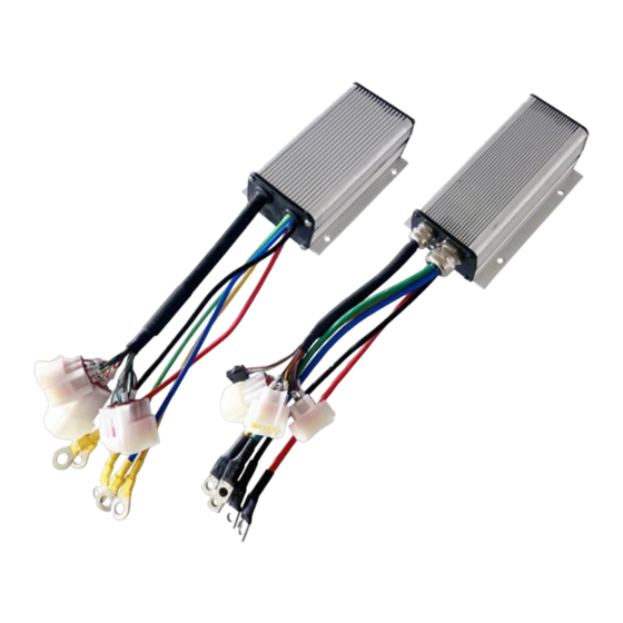
- Page 1 Kelly SPM Mini Full Bridge 4Q Permanent Magnet Motor Controller User’s Manual V1.1 Kelly SPM Mini Full Bridge 4Q Permanent Magnet Motor Controller User’s Manual Devices Supported: SPM4812S SPM7212S SPM4818S SPM7218S Rev1.1 Feb. 2023...
-
Page 2: Table Of Contents
Kelly SPM Mini Full Bridge 4Q Permanent Magnet Motor Controller User’s Manual V1.1 Contents Chapter 1 Introduction ................. 2 1.1 Overview ................... 2 Chapter 2 Features and Specifications ............2 2.1 General functions ................2 2.2 Features .................... 3 2.3 Specifications ..................4 Chapter 3 Wiring and Installation .............. -
Page 3: Chapter 1 Introduction
Kelly‟s SPM motor controller is full bridge or 4 quadrant controller. It provides fast and reliable electronic direction control. There is no arc, spark, or life limit on motor direction changes. -
Page 4: Features
Kelly SPM Mini Full Bridge 4Q Permanent Magnet Motor Controller User’s Manual V1.1 (17) Enhanced regen brake function. A novel ABS technique provides powerful and smooth regen. (18) Configurable 12V brake signal input, in lieu of motor temperature sensor. (19) Optional joystick throttle. A bi-symmetrical 0-5V signal for both forwarding and reversing. -
Page 5: Specifications
Kelly SPM Mini Full Bridge 4Q Permanent Magnet Motor Controller User’s Manual V1.1 2.3 Specifications (1) Frequency of Operation: 16.6kHz. (2) Standby Battery Current: < 0.5mA. (3) 5V Sensor Supply Current: 40mA. (4) Controller supply voltage range, PWR, 18V to B+. -
Page 6: Chapter 3 Wiring And Installation
Kelly SPM Mini Full Bridge 4Q Permanent Magnet Motor Controller User’s Manual V1.1 Chapter 3 Wiring and Installation 3.1 Mounting the Controller The controller can be oriented in any position which should be as clean and dry as possible, and if necessary, shielded with a cover to protect it from water and contaminants. - Page 7 Kelly SPM Mini Full Bridge 4Q Permanent Magnet Motor Controller User’s Manual V1.1 mounting holes‟ dimensions Figure 2:SPM-18S (dimensions in millimeters)
-
Page 8: Connections
Kelly SPM Mini Full Bridge 4Q Permanent Magnet Motor Controller User’s Manual V1.1 3.2 Connections 3.2.1 Pin definition of SPM Controller waterproof connector Figure 3: DJ7091Y-2.3-11 Pin Definition (14) REV_SW: Reverse switch input. Orange (6) RTN: Signal return or power supply return. Black... - Page 9 Kelly SPM Mini Full Bridge 4Q Permanent Magnet Motor Controller User’s Manual V1.1 Notes: 1. All RTN pins are internally connected. 2. Kelly Ammeter positive connect to 5V power supply of controller, negative to Dark Blue wire. 3. Switch to ground is active. Open switch is inactive.
- Page 10 Kelly SPM Mini Full Bridge 4Q Permanent Magnet Motor Controller User’s Manual V1.1 3.2.2 Wiring of SPM Controller 3.2.2.1 Standard wiring of SPM controller Figure 4: SPM controller standard wiring (Battery voltage can be used for controller supply)
- Page 11 Kelly SPM Mini Full Bridge 4Q Permanent Magnet Motor Controller User’s Manual V1.1 3.2.2.2 Optional wiring of SPM controller The output signal of the pin is for Kelly current meter. Figure 5: Wiring of current meter pin The 12V input signal of the pin supplies the second braking function of the controller.
-
Page 12: Installation Check List
Kelly SPM Mini Full Bridge 4Q Permanent Magnet Motor Controller User’s Manual V1.1 3.3 Installation Check List Before operating the vehicle, complete the following checkout procedure. Use LED code as a reference as listed in Table 1. Caution: • Put the vehicle up on blocks to get the drive wheels off the ground before beginning these tests. -
Page 13: Chapter 4 Maintenance
But it will affect the Identification angle operation. Please try to eliminate the error codes before Identification angle operation. • Use a straight through RS232 cable or USB converter provided by Kelly to connect to a host computer. Provide >+18V to PWR(7). Wire power supply return(supply negative) to any RTN pin. -
Page 14: Green Led Codes
Kelly SPM Mini Full Bridge 4Q Permanent Magnet Motor Controller User’s Manual V1.1 Table 1: LED CODES Green LED Codes LED Code Explanation Solution No power or Green Off 1. Check if all wires are correct. switched off 2. Check fuse and power supply. -
Page 15: Contact Us
Kelly SPM Mini Full Bridge 4Q Permanent Magnet Motor Controller User’s Manual V1.1 a temporary over-current, momentarily high or low battery voltage. This can happen during normal operation. Hall throttle is open ¤¤¤ ¤¤¤ When the throttle is repaired, a restart will clear the or short-circuit fault.


