Advertisement
Advertisement
Table of Contents

Related Manuals for SANJIANG JB-FSD-982E


Summary of Contents for SANJIANG JB-FSD-982E
- Page 1 Version number: 5025131129 Fire indicating panel JB-FSD-982E Page 1 of 6...
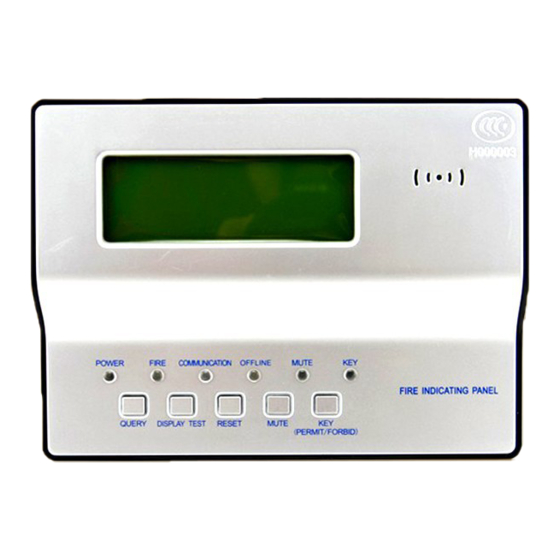
- Page 2 ----- I. Product overview The JB-FSD-982E fire indicating panel (indicating panel for short) is a kind of microprocessor- controlled fire indicating panel developed by our company. Each indicating panel is connected to a fire alarm control panel produced by our company via a special RS-485 interface to process and display the data sent from the fire alarm control panel.
- Page 3 V. Use and engineering application 1.Fig.2 is the schematic diagram of the terminals of a indicating panel. Definitions of terminals: 1 -- +24V (positive input terminal of the power supply) Address coding 2 -- GND (negative input terminal window of the power supply) Connecting 3--OFF (reserved terminal) 4 -- COM (reserved terminal)
- Page 4 panel. For more details, see 10) Setup of address parameters and control system. The indicating panel can display 99 fire alarm messages or feedback messages. When set to the floor display mode, each indicating panel can display all the fire alarms of the floor. When there are multiple fire alarms, the equipment will display them in an automatic rolling way.
- Page 5 panel can also realize the reset function. 7)Query After the equipment receives two or more fire alarm messages, it will display the fire alarm messages automatically and circularly. After the QUERY key is pressed after the keyboard lock is unlocked, the equipment will enter the manual display status. Each time after the QUERY key is pressed, the equipment will display the next fire alarm message.
- Page 6 A JB-FSD-982E fire indicating panel consists of a base and a indicating panel. It is subject to a wall-mounted installation. Its external wires may be directly connected with the terminals on the rear panel of the indicating panel. See Fig.9 for the schematic diagram of the mounting base of the indicating panel.
Need help?
Do you have a question about the JB-FSD-982E and is the answer not in the manual?
Questions and answers