Table of Contents
Advertisement
Quick Links
Instruction Manual of SG-991E Fire Alarm Horn/Strobe
------ Please read this Manual carefully before installing and using the product. -----
I. Product overview
The SG-991E fire alarm horn/strobe (horn/strobe for short) is a kind of product manufactured by our company to be used with
bus-type fire alarm control units. Controlled by a microprocessor, the horn/strobe can realize real-time communication with a
bus-type fire alarm control unit and receive the control commands sent by it. When in a routing inspection, the red status
indicator will blink; after an accident happens, the horn/strobe will start to operate after
receiving a startup command from the bus-type fire alarm control unit. The red status
indicator will remain lit and the horn/strobe will give a flashing signal and an audible
alarm signal to notify the persons on the scene of the accident that a fire has occurred
on the site and of the necessity to take related evacuation measures, thus preventing
the fire accident from becoming a major one. The horn/strobe may be restored to the
monitoring status after the MUTE or RESET key on the bus-type fire alarm control unit
is pressed.
The horn/strobe may be used to give audible alarms and flashing alarms on the
scenes of accidents. It is suitable for places like high-rise residential buildings, public
places, hotels, amusement buildings, factories, shopping centers, hospitals, schools,
office buildings and stock exchanges, particularly places with low visibility or the
possibility of generation of smoke.
II. Product features
ü
It can realize complete electronic coding and in situ rewriting with the help of a
coder.
ü
The audible alarm and flashing alarm may be set freely. In other words, the horn/strobe may give an audible alarm
and a flashing alarm at the same time or separately and it can be adapted to different working environments.
ü
Designed with an upper cover and a lower cover, it can be installed, debugged and maintained conveniently.
ü
It uses multiple super bright red LEDs as light sources for visual display, ensuring a striking display, a longer service
life and low power consumption.
III. Technical parameters
1.
Executive standard: GA385- 2002
2.
Operating voltage: DC24V (pulse modulation)
Operating current: quiescent current: ≤1mA (the current consumed by the bus); alarm current: ≤120mA@DC24V
3.
Operating environment: Temperature: -10℃~+55 ; relative humidity: ≤95% (40 , without condensation)
4.
5.
Flushing rate: one time/s
6.
Alarm volume: >85dB (measured at a place 3m in front of the horn/strobe)
7.
Coding method: Electronic coding
8.
Wiring method: Four-wire system, non-polarity two signal buses (L1, L2) and power lines (+24V, GND)
9.
Matched host machine: JB-QBL-MN/300E
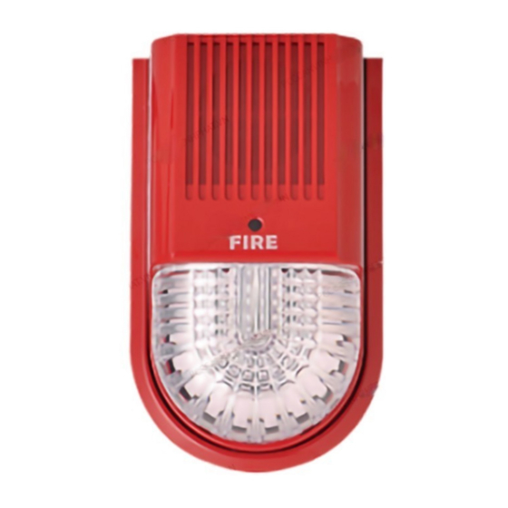
IV. Appearance and dimensions (see Fig.1)
V. Use and engineering application
1
Fig.2 is the schematic diagram of the rear cover of the horn/strobe.
Version: 2026100811E
℃
℃
Fig.1
1
Connecting terminal
Debugging port
Enlarged drawing
2. Selection between audible alarm and flashing alarm: Select through the jumper (JP1) below the
debugging port lid on the back of the horn/strobe, following the instructions of the jumper.
Jumper setup
Warning: The output mode of a horn/strobe can be one of the three options in the table
above only.
3.
Fig.3 shows the general functions and wiring diagram of the product.
4. Address coding: When a horn/strobe is coded, it is unnecessary to disassemble the wire connecting it
with the host machine; online coding may be done. The specific method is as follows: Open the cover
of the coding setup window, insert the output plug (a four-pin connector) of the coder into the address
coding socket (the socket J2 in Fig.2) of the horn/strobe, set the coder with the coding function,
compile the correct address code and press the RUN key to complete the address coding. (Note: See
the User's Manual of the coder for detailed operation information.)
Warning: It is necessary to have "online coding" done when the system is powered off
or related equipment may be damaged.
Definitions of terminals:
1---+24 power input terminal
2---GND power ground
3---Bus input terminal L1
4---Bus input terminal L2
JP1: Setup of selection between
audible alarm and flashing alarm
J2: Address coding socket
Fig.2
Function
Audible alarm and flashing alarm (factory
default)
Flashing alarm (no audible alarms will be
given)
Audible alarm (no flashing alarms will be
given)
Fig.3
2
Advertisement
Table of Contents

Related Manuals for SANJIANG SG-991E


Summary of Contents for SANJIANG SG-991E
- Page 1 2---GND power ground I. Product overview 3---Bus input terminal L1 The SG-991E fire alarm horn/strobe (horn/strobe for short) is a kind of product manufactured by our company to be used with 4---Bus input terminal L2 Debugging port bus-type fire alarm control units. Controlled by a microprocessor, the horn/strobe can realize real-time communication with a bus-type fire alarm control unit and receive the control commands sent by it.
- Page 2 We may provide a paid repair service for the products with any faults beyond the guarantee range. If you have such Usage: Do not connect the power supply until the address of the horn/strobe has been set and products needing repair, please contact us. When sending such a product to us for repair, you are expected to provide confirmed and the fire alarm control panel has been properly connected.
Need help?
Do you have a question about the SG-991E and is the answer not in the manual?
Questions and answers