
Related Manuals for ECKELMANN UA 410 L


Summary of Contents for ECKELMANN UA 410 L
- Page 1 Operating instruction Temperature Data Logging Controller UA 410 L Controller for temperature data logging Firmware V3.03 14.02.2023 Docu 4.0...
- Page 2 Copyright: All rights to any use whatever, utilisation, further development, forwarding and creation of copies remain with the Eckelmann AG company. In particular, neither the contract partners of Eckelmann AG nor other users have the right to distribute or market the IT programs/program parts or modified or edited versions without express written permission.
-
Page 3: Table Of Contents
Five Safety Rules According to DGUV Regulation 3 ................10 Electrostatic-Sensitive Components and Control Components (ESD)..........11 2.5.1 ESD - Rules for Handling and Working ....................11 Abbreviations Used..........................11 System Design of UA 410 L ........................12 Application ..............................12 Connectors .............................13 Application of UA 410 L .........................14 Versions ..............................14 Controller Type ............................15... - Page 4 6.6.2.1 Update for Controller with 8-Pole DIP Switch...................48 6.6.2.2 Update for Controller with 9-Pole DIP Switch...................53 6.6.3 Rectification of Driver Problems .......................56 Connection and Terminal Assignment UA 410 L.................57 Connectors for 230 V AC ........................58 7.1.1 Assignment of the 230 V AC Power Supply .....................58 7.1.2...
- Page 5 8.3.4.1 System Centre - Service Mode ........................79 8.3.4.2 Store Computer CI 3x00 - Service-Mode ....................80 Menu Structure of UA 410 L ........................81 Controller type UA 410 L – Menu tree (Rx.1..Rx.0) ................81 Main Menu ...............................82 Menu 1 Actual Value..........................82 Menu 2 Setpoints............................83 Menu 3 Clock ............................84...
-
Page 6: Conventions
1 Conventions 1.1 Warning Signs, Symbols and Text Formatting used in this Manual Explanation of the warning signs, symbols and text formatting used in this operating and service manual: • DANGER DANGER Instructions with this symbol and/or the signal word DANGER warn the user of situations that will cause severe injury or death if the specified instructions are not observed! * •... -
Page 7: Explanation Of Text Formatting
A general instruction consists of two elements: The symbol with text (including NOTICE, if applicable) and the text of the instruction: For example: NOTICE The current operating manual is available online from the E°EDP (Eckelmann ° Electronic Documentation Platform) at www.eckelmann.de/elds. Firmware V3.03 14.02.2023 7/97... -
Page 8: Safety Instructions
2 Safety Instructions This operating manual is part of the device. It must be kept in the vicinity of the controller as well as for future use so that it can be consulted when required. The operating manual must be available to the operating and maintenance personnel at all times in order to avoid operating errors. -
Page 9: Disclaimer In The Event Of Non-Compliance
ATTENTION Warning of damage to goods! In our experience, the transmission of fault messages is not yet functional during the putting into service (no internet connection, no telephone line installed, etc.). It is strongly recommended in such cases to monitor the controller via the CAN bus using a system centre, a store computer or an operator terminal and to enable the transmission of fault messages, for example using a GSM modem via a mobile telephone system. -
Page 10: Intended Use
2.3 Intended Use The temperature recording controller UA 410 L AC has been developed for use for temperature recording of up to 10 temperature measuring points and their monitoring in commercial and industrial refrigeration systems and is designed with the functional framework described in this operating manual and under the ambient conditions described in this operating manual. -
Page 11: Electrostatic-Sensitive Components And Control Components (Esd)
Containers and worktops made of wood, metal or conductive plastics or paper bags 2.6 Abbreviations Used • DGUV Regulation 3 - Accident Prevention Regulation for Electrical Systems and Equipment (previously: BGV A3 - Employer’s Liability Association Regulation for Occupational Health and Safety) • DIN Deutsches Institut für Normung e.V. (German Standardisation Institute) • E°EDP/EDP Electronic Documentation Platform of Eckelmann AG • ESD Electrostatic-Sensitive Device • ESD Electro-static discharge (Electro Sensitive Devices) • IEC International Electric Committee •... -
Page 12: System Design Of Ua 410 L
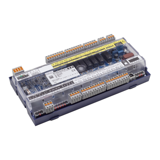
3 System Design of UA 410 L UA 410 L - full configuration 3.1 Application The UA 410 L AC temperature recording controller is based on the UA 400 hardware and has been developed for use in the temperature recording of up to 10 temperature measurement points and their monitoring. -
Page 13: Connectors
Real-time clock RTC, with power reserve, lithium cell (battery) • For precise details of the UA 410 L AC see chapter Versions. The connection and terminal configurationsare described in the chapter Connection and Terminal Assignment UA 410 Firmware V3.03 14.02.2023... -
Page 14: Application Of Ua 410 L
4 Application of UA 410 L 4.1 Versions The UA 410 L is only available in the AC* variant and has the following features: UA 410 L AC (complete design) For DIN rail mounting • For integration in the CAN bus of the E*LDS system •... -
Page 15: Controller Type
Special feature: Two device generations are available. The DIP switch S3 provides a quick distinguishing feature: Characteristic: 9-pole DIP switch Characteristic: 8-pole DIP switch Only the controller type "UA 410 L" is available for the UA 410 L: Set controller type DIP switch S3 (switch positions of the coding switches 1..9) UA 410 L ... -
Page 16: Function Of Ua 410 L
Caution: data loss! A first start causes all parameters to be reset to the factory settings! A first start is also performed when a different controller version (e.g. UA 400 / UA 410 D / UA 400 E / UA 410 L) is loaded on the controller via firmware update (see chapter Battery replacement). -
Page 17: Selection Of The Sensor Type
5.2 Selection of the Sensor Type The temperature recording controller uses 2-wire NTC temperature sensors for the regulation. UA 410 L AC (complete design) All connected sensors must be identical in their type and are not parametrised individually. The type of the sensor can be set with the parameter Fühlertyp (menu 6-2-5). -
Page 18: Required And Optional Sensors
Temperature Data Logging Controller. In addition to the sensors that should be monitored, the respective alarm priorities in the UA 410 L should also be set to the values 0 (message) or 1..2 (alarm signal). -
Page 19: Temperature Recording
5.3 Temperature Recording The temperature recording controller UA 410 L AC was designed for temperature recording of up to 10 measuring points and their Monitoring. The following temperature recordings are possible: • Temperature recording according to EU Regulation 37/2005 • Temperature Recording in the Controller Rx.1..Rx.0: Temperature sensors 1..10 for temperature recording. -
Page 20: Temperature Recording According To Eu Regulation 37/2005
UA 410 E. Conditions 1. The UA 410 L must be integrated together with a system centre in the E*LDS CAN bus system. 2. The UA 410 L must not be used to simultaneously control these refrigeration points. -
Page 21: Temperature Recording In The Controller
If the parameter EU Archive CAN is set to the CAN address of another case controller ((UA 400 / UA 4x0 E / UA 410 D), then its status will be recorded together with the temperature of the UA 410 L. -
Page 22: Cooling Via Solenoid Valve (Tev)
5.4 Cooling via Solenoid Valve (TEV) On-off control Control (with recording) is via a temperature sensor and is only possible with the first five temperature sensors Rx.1..Rx.5. The cooling relay 2..6 de-energizes when temperature reaches the setpoint (switch-off value, Menu 2) on the respective temperature sensor. -
Page 23: Defrosting (Recirculating Air Defrosting)
5.5 Defrosting (Recirculating Air Defrosting) Defrosting (available only with the first five temperature sensors Rx.1..Rx.5) frees the evaporator of ice forming from normal operation. Defrosting always takes place as recirculating air defrosting and during defrosting, temperature control of the refrigeration point is inactivated (cooling relay 2..6 = OFF). ... -
Page 24: Monitoring
5.6 Monitoring With the UA 410 L, up to 10 independent refrigeration points can be monitored in two groups. High and low temperature can be set for each temperature sensor (menu 2). A time delay and priority can also be set for each sensor. -
Page 25: Alarm Relay
CAN bus mode takes over the task of alarm signalling. 5.8 Real Time Clock The UA 410 L AC is equipped with a real-time clock. This clock is battery-backed and keeps running in an electric power failure, see chapter Battery Replacement. -
Page 26: Bt 30 Temperature Display
5.9 BT 30 Temperature Display Up to 4 BT 30 temperature displays can be connected to the case controller. The connection is made via an RJ45 distributor in a star configuration via the DISPLAY interface on the refrigeration controller: For details see chapter Assignment of the DISPLAY Interface. - Page 27 The following temperatures of a case controller or controller type can be displayed: Controller type Display of temperatures on the BT 30 in °C Address 1 Address 2 Address 3 Address 4 UA 410 L Rx.1 Rx.2 Rx.3 Rx.4 Wire loop - BT 30 configuration green wire...
-
Page 28: Installation And Start-Up Ua 410 L
6.1 Installation The Temperature Data Logging Controller is produced in the type UA 410 L AC. UA 410 L AC - full configuration - Electrical enclosure and dimensions are listed in Section Specifications of UA 6.1.1 DIN Rail Mounting of the Temperature Data Logging Controller The controller is attached to the DIN rail (35 mm) using two retaining springs. -
Page 29: Mounting On The Din Rail
6.1.1.1 Mounting on the DIN rail Warning about dangerous electrical voltage! Danger to life - Danger of electric shock! The safety instructions and work safety instructions must be observed for the mounting. All plug connectors may only be inserted and removed when the power supply is disconnected. Step 1: The two retaining springs on the underside of the device must be pulled out using a flat-blade screwdriver until they click into place. - Page 30 Step 2: Place the case controller on the top edge of the DIN rail (A) and swivel downwards until the case controller is positioned on the lower edge of the DIN rail. Step 3: Press in the two retaining springs until they click into place and check that the case controller is firmly attached to the DIN rail. The controller can be put into operation after completion of the mechanical and electrical installation of the case controller.
-
Page 31: Disassembling From The Din Rail
6.1.1.2 Disassembling from the DIN rail Warning - hazardous electrical voltage! Danger to life - Danger of electric shock! When disassembling the safety instructions and work safety instructions must be observed. All connectors may only be connected and disconnected when power is off. Step 1: Pull all mating plugs with cable from the case controller. -
Page 32: Handling Of The Spring Terminals
6.1.2 Handling of the Spring Terminals Mating connectors with spring terminals (push-in spring connection) and has the following features: • Conductors with cross sections between 0.25 and 2.5 mm² can be used. • All mating connectors are coded and any reverse polarity is therefore ruled out. A - Installation For fast installation without tools, direct conductor connection of prefabricated cables (these with 10 mm wire end sleeves) by simply inserting into the spring terminal is also possible. The orange push button must also be ... -
Page 33: Basic Configuration
6.2 Basic Configuration Settings BEFORE the connection of the power supply - S1, S2, S3 • Decade switches S1 and S2: - Setting of the CAN bus address (node number) 1..99, see chapter Setting CAN Bus Address • DIP switch S3: - Controller type setting - Master / Slave mode - Setting of special functions, see chapter Setting the Controller Type Settings AFTER application of the power supply •... -
Page 34: Setting Can Bus Address
6.2.1 Setting CAN Bus Address Setting of the CAN bus address (Kn.nnn = 1..99) is performed using the two decade switches S1 and S2. An individual CAN bus address must first be set at the two decade switches on all case controllers that are installed in refrigerated cases before commissioning. -
Page 35: Setting The Controller Type
Setting of the controller type in normal operation (DIP switch S3/Coding Switch 9 always ON) Controller type DIP Switch S3 (Coding Switch positions 1 to 9) UA 410 L OFF OFF OFF OFF OFF OFF OFF OFF ON ... -
Page 36: Assignment For 230 V Ac Power Supply
6.3 Assignment for 230 V AC Power Supply DANGER Warning - hazardous electrical voltage! Danger to life - Danger of electric shock! BEFORE and AFTER connection it must checked that the 230 V AC supply cable is off load! The power supply cable is connected to the case controller using the right hand terminal block PE/L/N: The case controller can now be supplied with power. -
Page 37: Status Leds
6.3.1 Status LEDs DANGER Warning about dangerous electrical voltage! Danger to life - Danger of electric shock! The device must never be operated without its case. Before opening the case, the device must be disconnected from the power supply. Function Colour Description... - Page 38 Firmware V3.03 14.02.2023 38/97...
-
Page 39: Basic Configuration Of The Controller
2a. Special case UA 410 L In contrast to the other controllers in the UA 400 series, the required sensor must be selected previously on the UA 410 L to reach the main menu of any temperature sensor (Rx.1..Rx.0): Main Menu ... - Page 40 Number of sensors. The number of sensors connected is scanned on exiting the parameter by pressing ENTER. * Any naming of the controller with a BT 300 x operator interface is only possible for the UA 410 L controller. ...
- Page 41 1 to 2 Temperature zone of case/coldroom controller 3 to 10 Temperature sensor (e.g. another UA 410 L in the system) 9. Changing the basic configuration of the controller Return to the main menu by repeatedly pressing the ESC key.
-
Page 42: Designation Of The Controller And The Sensors
The designation can be made as follows: • BT 300 operator interface The input is made in Menu 6-1. Note: Any designation of the controller with a BT 300 x operator interface is only possible for the UA 410 L controller! •... -
Page 43: Battery Replacement
6.5 Battery Replacement Only UA 410 L AC The controller has a buffer battery of the type CR 2450 N, 3 V Lithium. In order to change the battery, it is necessary to remove the controller from the system. In this case, the refrigeration point is not regulated, reorded and monitored! ... - Page 44 Performing the battery replacement Disconnect case controller and refrigeration point from the power supply. Acknowledge alarm in the higher level controller if necessary. Disconnect all plug connectors, remove the device from the DIN rail. DANGER Warning about dangerous electrical voltage! Danger to life - Danger of electric shock! A voltage of 230 V AC can be present on some connectors.
-
Page 45: Firmware Update
Put device on the DIN rail and attach all connectors again. DANGER Warning about dangerous electrical voltage! Danger to life - Danger of electric shock! A voltage of 230 V AC can be present on some connectors. Restore power to the case controller and refrigeration point. Refrigeration point operates again. Controller in the CAN bus system: With unchanged configuration of the system centre, the controller is automatically detected again via the CAN bus;... -
Page 46: Requirements For Firmware Update
6.6.1 Requirements for Firmware Update The following components are required for a firmware update: • The controller for which the update is intended. Special feature: Two device generations are available. The DIP switch S3 provides a quick distinguishing feature: 2nd generation controller 1st generation controller (from Oct. - Page 47 Step 1: Install software Before the first connection of the controller to the PC, the installation program "Firmware_Uploader_Setup_vxx.exe" must first be executed once. Please follow the instructions given by the installation wizard. The components to be installed can be selected in the following window. Then select the target directory: The installation of "Microsoft Visual C++ 2013 Redistributable"...
-
Page 48: Installing Firmware Update
No error message such as "USB device not found" should be displayed on the laptop or PC. * * Further information: • USB cable: see chapter Order numbers and accessories of UA 410 L • Installation program & firmmware: see https://edp.eckelmann.de/edp/lds/_Y2OqwfWgBx • Tips for Rectification of Driver Problems 6.6.2 Installing Firmware Update... - Page 49 Practical tip: The original position of the coding switches 1..8 of the DIP switch S3 should be documented, e.g. with a mobile telephone photo. Before starting the firmware update, all coding switches 1..8 of the DIP switch S3 must be set to ON: After the firmware update has been performed, the coding switch 9 of DIP switch S3 must be reset to its original position.
- Page 50 No error message such as "USB device not found" should be displayed on the laptop or PC. Otherwise, tips for rectifying driver problems are explained in more detail in the chapter Rectification of driver problems. Firmware V3.03 14.02.2023 50/97...
- Page 51 Step 3: Perform firmware installation Under "Start / Programs / ECKELMANN / Firmware Uploader", start the program "KGL Firmware Uploader". The following window opens: Click the "Find Controller" button to find the controller. A notification is displayed in the status field if the controller has been found. Then select the current firmware file ("xxx.bin") from the directory into which the ZIP file was extracted (see arrow).
- Page 52 After the conversion, tap the button "Update firmware" to start the firmware upload: The program can be ended after the successful firmware update by closing the window. The USB A-B cable can now be disconnected from the controller. Step 4: DIP switch S3 in original position again After the firmware update has been performed, all coding switches 1..8 of the DIP switch S3 must be returned to their original position.
-
Page 53: Update For Controller With 9-Pole Dip Switch
6.6.2.2 Update for Controller with 9-Pole DIP Switch Controller characteristic: 9-pole DIP switch The settings depend on the controller type! The steps described in the chapter Requirements for Firmware Update must have been performed once for each PC in order to perform a successful firmware update. Step 1: Set DIP switch S3 and connect controller to PC ... - Page 54 Under "Start / Programs / ECKELMANN / Firmware Uploader", start the program "KGL Firmware Uploader". The following window opens: Click the "Find Controller" button to find the controller. A notification is displayed in the status field if the controller has been found. Then select the current firmware file ("xxx.hex") from the directory into which the ZIP file was extracted (see arrow).
- Page 55 The program can be ended after the successful firmware update by closing the window. The USB A-B cable can now be disconnected from the controller. Step 3: Reset DIP switch S3 After performing a firmware update, only the coding switch 9 of the DIP switch S3 must be reset to ON: ...
-
Page 56: Rectification Of Driver Problems
6.6.3 Rectification of Driver Problems If the driver installation is not complete or if the controller has been accidentally connected to the PC before the execution of the installation program, the following instructions will provide you with information for how the problem can be rectified: Problems with USB connections: Problems with the detection of controllers on the USB3 port may occur. -
Page 57: Connection And Terminal Assignment Ua 410 L
In order to guarantee reverse polarity protection, only coded mating connectors may be used on the connectors of the controller. Connection diagram of the controller with terminal designation, here pictured in the full configuration UA 410 L AC. A detailed description of the connection and terminal configuration of the controller and its components is contained on the following pages. -
Page 58: Connectors For 230 V Ac
7.1 Connectors for 230 V AC 7.1.1 Assignment of the 230 V AC Power Supply DANGER Warning - hazardous electrical voltage! Danger to life - Danger of electric shock! BEFORE and AFTER connection it must checkedthat the 230 V AC supply cable is off load! Controller Type Terminal No. Function All controllers Ground conductor... -
Page 59: Assignment Of The 230 V Ac Relay Outputs
Relay 4 Relay 3 Relay 2 Relay 1 Controller type 74/73 64/63 54/53 44/43 38/36/35 28/26/25 18/16/15 UA 410 L Not used Cooling 5 Cooling 4 Cooling 3 Cooling 2 Cooling 1 Alarm If any relay output is activated by the controller, the associated green LED lights, see chapter Status LEDs for details. Firmware V3.03 14.02.2023... -
Page 60: Assignment Of The Digital Inputs 230 V Ac
3 input 2 input 1 Controller type D42/D41 D32/D31 D22/D21 D12/D11 UA 410 L – Suppression of temperature alarms in case of Cooling high/low temperature, see chapter Monitoring enabled/disabled* Group 2: Rx.6 bis Rx.0 Group 1: Rx.1 bis Rx.5 enabled/disabled* enabled/disabled* ... -
Page 61: Connectors For Safety Extra-Low Voltage
AO2 (+ 0..10 V) – without function – – AO1 (+ 0..10 V) without function *As of 2023, the UA 410 L controllers will be delivered without analogue outputs, on older controllers these are without function. Firmware V3.03 14.02.2023 61/97... -
Page 62: Assignment Of The Can Bus
For further details on the setting of the CAN bus address see chapter Setting CAN Bus Address. Controller Type Terminal No. CAN bus Lead colour UA 410 L Shielding (SHLD) Shielding CAN-GND green CAN-LOW brown CAN-HIGH white ... -
Page 63: Assignment Of The 24 V Dc Transistor Outputs
91: 24 V DC / max. 50 mA 82: OUT 92: OUT 83: GND 93: SHIELD UA 410 L Without function Without function If any transistor output is activated by the controller, the associated green LED lights, see chapter Status LEDs for details. -
Page 64: Assignment Of The Display Interface
7.2.4 Assignment of the DISPLAY Interface DANGER Warning about dangerous electrical voltage! If mains power is connected to this interface, this results in destruction of the controller! An operator interface of the BT 300 series (e.g. for service purposes) and/or up to four BT 30 temperature displays can be connected to the DISPLAY interface. -
Page 65: Assignment Of The 4
As a general rule, care should be taken to ensure that signal cables and cables carrying mains voltage are routed in separate cable channels. Connection of pressure transmitters / humidity sensors (only analogue input 2) Controller type Terminal No. Analogue input AIN1 Analogue input AIN2 UA 410 L +24 V DC +24 V DC AIN1 (4..20 mA) – sans fonction –... -
Page 66: Assignment Of The Analogue Inputs Of Temperature Sensors
Sensor 6 Sensor 7 Sensor 8 Sensor 9 Sensor 10 Type Terminal No. Z11/Z12 Z21/Z22 Z31/Z32 Z41/Z42 Z51/Z52 Z61/Z62 Z71/Z72 Z81/Z82 Z91/Z92 Z01/02 UA 410 L Rx.1 Rx.2 Rx.3 Rx.4 Rx.5 Rx.6 Rx.7 Rx.8 Rx.9 Rx.0 Firmware V3.03 14.02.2023 66/97... -
Page 67: Assignment Of The Usb Interface
7.2.7 Assignment of the USB Interface The USB port is used for direct parametrisation of the case controller via LDSWin or for performing a firmware update of the controller or for parametrisation of system components via CAN bus using LDSWin (USB2CAN). Furthermore, the operating data of the case controller can be read out via the USB port using a PC equipped with LDSWin. -
Page 68: Wirksinn Der Relais- Und Transistor-Ausgänge
Relay outputs 230 V AC Transistor outputs 24 V DC/50 mA Controller type Cooling Alarm 81/82/83 91/92/93 UA 410 L Positive Inverted Without function Without function Mode of operation „positive" means that operation of the relay is not inverted:The relay is energized when the controller activates the function output (e.g. -
Page 69: Operation Of Ua 410 L
8 Operation of UA 410 L 8.1 Operation Possibilities The controller provides menus and screens for the display and adjustment of values. However, no operation for this is provided on the controller itself. The following options are available for operating the controller: •... -
Page 70: Local Operation With A Bt 300 X Operator Interface
8.2 Local Operation with a BT 300 x Operator Interface An operator interface in the BT 300 series is connected locally via the DISPLAY interface. Thereby, the controller can be operated standalone as shown or also connected to the CAN bus. The operation here largely corresponds to the possibilities as described for the system centre, the store computer and the operator terminal; see chapter Menus and Operating Screens for details. -
Page 71: Lock-Down Of The Setpoint Change
8.2.1 Lock-down of the Setpoint Change The operator interfaces of the BT 300 series can be locked using a jumper on the circuit board so that all actual values, parameters, temperatures and statuses can be viewed, but so that it is no longer possible to adjust the setpoints of the respective controller. Jumper configuration A: with setpoint change (factory setting) B: without setpoint change ... -
Page 72: Remote Control Via A Terminal
8.3 Remote Control via a Terminal For the remote control of a controller, it makes no difference whether this is done with a system centre (A) or with an operator terminal (B) as the user interfaces on the terminals are almost identical and the same functions are available. See chapter Calling the Controller Menu via Remote Control for details about remote control. -
Page 73: Menus And Operating Screens
8.3.1 Menus and Operating Screens If the system centre, store computer or operator terminal remain locked down, settings on the controller are read-only. Changes and inputs are not possible. However, if any parametrisation is required, the lock-down for the input must be removed first, see chapter Deactivating the Input Lock- down. - Page 74 Menus A menu can contain up to ten menu items (0 .. 9; 0 for menu item 10). After the selection of a menu item using the cursor buttons ( ) and ( ) and by tapping the ENTER button ( ) or by tapping the buttons 0..9), other submenus or operating screens are displayed.
-
Page 75: Calling The Controller Menu Via Remote Control
Deleting input text The MODE button and - must be pressed simultaneously to delete the complete text line. A character is deleted using the button combination MODE and , . Cancelling of an entry The entry of a value can be cancelled by tapping the ESC button. The value is not applied. Entering text In fields that allow text entry, text can also be entered by the alphanumeric keypad. -
Page 76: System Centre
8.3.2.1 System Centre The terminal for remote control of the controller (Menu 2-2 or Menu 4-2) is called in the system centre as follows: Step 1: Tap "2 - System overview" or "4 - Configuration" in the main menu. If "2" is selected, the values below are only displayed as read-only, for "4", lock-down must previously be removed by logging in (Deactivating the Input Lock-down) so that settings below can be made. Step 2: Tap "2 Case controllers" and select the required controller in the list that is then displayed using the cursor buttons (↑) and (↓). In the screen that opens, the name, position designation and the alarm priority of the controller can be input as required. Step 3: The main menu of the controller is then displayed by tapping the "Remote control"... -
Page 77: Deactivating The Input Lock-Down
8.3.3 Deactivating the Input Lock-down Operation via system centre, store computer or operator terminal is only possible for controllers with CAN bus connection; the removal of the lock-down is then applicable for all components in the CAN bus system. The lock-down is automatically reactivated 15 minutes after the last button tap. The release of the lock-down must only be carried out by service personnel. 8.3.3.1 System Centre Unlocking If any configuration of components is required, the input must be unlocked. -
Page 78: Store Computer Ci 3X00 / Operator Terminal Al 300 Unlocking
8.3.3.2 Store Computer CI 3x00 / Operator Terminal AL 300 Unlocking Before entering values, the input lock must be removed from the store computer or operator terminal as follows: Step 1: Select menu item 9 "Parametrisation" in the main menu. Step 2: Select menu item 3 "Lock-down"... -
Page 79: Activating Service Mode
8.3.4 Activating Service Mode For repair and maintenance work, service personnel can deactivate the remote alarm function of the system centre and of the store computer for a limited period using the service mode. The activation of the service mode must only be carried out by service personnel. If there are still pending alarms (with the priority 1..2) after the time of the Service Mode has elapsed, the audible warning devices and the alarm relays are activated and the alarms are forwarded using the automatic transmission of alarms. -
Page 80: Store Computer Ci 3X00 - Service-Mode
8.3.4.2 Store Computer CI 3x00 - Service-Mode Activating/deactivating service mode Step 1: Select menu item 9 "Parametrisation" in the main menu. Step 2: Select menu item 3 "Lock-down" in this menu. Step 3: Tap the buttons MODE + ENTER (.) simultaneously to open the screen for the suppression of the remote alarm signalling and input the service duration (1..255 minutes). The service mode is now activated ... -
Page 81: Menu Structure Of Ua 410 L
Select 1st temperature sensor Rx.1 2 Temp. Rx.2 Select 2nd temperature sensor Rx.2 0 Temp. Rx.0 Select 10th temperature sensor Rx.0 9.1 Controller type UA 410 L – Menu tree (Rx.1..Rx.0) DIP switch S3 UA 410 L 1..8: OFF 9: ON With few exceptions, the screens of the menu tree have the same structure for all 10 temperature sensors. -
Page 82: Main Menu
9.2 Main Menu Temp. Rx.y POS: XXXXX 1 Actual Value Move to menu 1 2 Setpoints Move to menu 2 3 Clock Move to menu 3 4 Messages Move to menu 4 5 Archive Move to menu 5 6 Configuration Move to menu 6 9.3 Menu 1 Actual Value... -
Page 83: Menu 2 Setpoints
1..2: One of the two temperature zones of the refrigeration controller, e.g. from a UA 410 E. 3..10: Temperature sensor x.3..x.0 of another UA 410 L in the system. For details see chapter Temperature recording according to EU Regulation 37/2005. -
Page 84: Menu 3 Clock
9.5 Menu 3 Clock CLOCK POS: XXXXX 1 Current Time Move to menu 3-1 2 Defrost Timer Move to menu 3-2 • Menu 3-1 Current Time When connected to the CAN bus, the default time is provided via the time master (system centre / store computer, operator terminal). Any entry made will then be overwritten by the default value. ... -
Page 85: Menu 4 Messages
9.6 Menu 4 Messages MESSAGES POS: XXXXX 1 View Move to menu 4-1 Show message log 2 Acknowledge Messages in message log are cancelled; alarms are cancelled after being shown:press ESC to go back 3 Delete Move to menu 4-3 •... -
Page 86: Menu 5 Archive
9.7 Menu 5 Archive The sensor wanted must first be selected to open the archives of a temperature sensor (Rx.1..Rx0): ARCHIVE POS: XXX 1 Temp. Rx.1 Select 1st temperature sensor Rx.1 2 Temp. Rx.2 Select 2nd temperature sensor Rx.2 0 Temp. Rx.0 Select 10th temperature sensor Rx.0 Following selection, the following menu will appear: Temp. Rx.y POS: XXXXX dd.mm.yy hh:mm Time of archiving Record 1 Zone 1: ab x °C Status and temperature of Zone 1, see Note *) -
Page 87: Menu 6 Configuration
9.8 Menu 6 Configuration CONFIGURAT POS: XXXXX 1 Refriger. Point Move to menu 6-1 2 Controller Move to menu 6-2 3 Language Move to menu 6-3 • Menu 6-1 Refriger. Point A meaningful name that describes the refrigeration point in more detail should be entered, e.g. Cheese Counter 2 and CC2. -
Page 88: Language
• Menu 6-2-2 Sensor Type Entry chooses between values. Checkmark indicates current setting. SENSORS POS: XXXXX Entry Default L243 √ Temperature range -50 .. 50°C (sensor type K243 is √ identical with L243) K277 Temperature range -50 .. 50°C 5K3A1 Temperature range 0 .. 100°C • Menu 6-3 Language LANGUAGE POS: XXXXX Entry... -
Page 89: Decommissioning And Disposal
Users have the option of returning a B2B device distributed by us to us at the end of its service life. Please contact your customer service representative at Eckelmann AG to arrange for the device to be taken back and disposed of properly. Please inform yourself about the local regulations for the separate disposal of electrical and electronic products and batteries. -
Page 90: Alarms And Messages Of Ua 410 L
11 Alarms and Messages of UA 410 L Message Cause Correction Hardware faults EEPROM Fault Component for saving configuration defective or Save parameters in LDSWin software, perform configuration data in EEPROM implausible. first start if necessary and load parameters from LDSWin. -
Page 91: Alarm Signaling And Monitoring
11.1 Alarm signaling and monitoring 11.1.1 High or Low Temperature Alarm High or low temperature is alarmed when temperature rises or falls to the alarm setpoint and the set delay has expired. The high and low temperature setpoints are entered in C. High and low temperature setpoints can be set separately for each temperature zone. The time delay applies to both temperature zones together. This alarm is inactive during defrosting. ... -
Page 92: Sensor Break Alarm
11.1.4 Sensor Break Alarm Alarm is generated after the set delay expires (Menu 6-2-1) if the controller detects breakage or short circuit on a sensor. This delay time is global for the controller and applies equally for all sensors. Sensor break alarm is only generated when priority of the sensor concerned is set to a value other than "-". -
Page 93: Message Log
11.2.2 Message log A maximum of 25 alarms and messages with receive and send date and time are entered in the message log and are stored in a ring buffer. When the ring buffer is full, the next new entry deletes the oldest entry. Priority 0 alarms are only entered in the message log. -
Page 94: Specifications Of Ua 410 L
12 Specifications of UA 410 L 12.1 Electrical data Warning - hazardous electrical voltage! Danger of electric shock! Overvoltage category III (test voltage 4,0 kV) / pollution degree 2: All device connections designed for use with 230 V AC supply voltage must be connected to the same phase conductor. - Page 95 2002/95/EG (RoHS)2004/108/EG (EMC Directive) 2006/95/EG (Low Voltage Directive) (Software class A - EN 60730-1, appendix A)DIN EN 12830 (Temperature logging devices) Supplement to standard DIN EN 12830 for temperature recorders (UA 410 L AC with L243 temperature sensor) Type of recorder Suitable for storage General requirements Measuring range -50 °C ...
-
Page 96: Mechanical Data
12.2 Mechanical data DIN rail mounting (A): Connector set with cable, all dimensions in mm 12.3 Mechanical data of the temperature sensor L243 / 5K3A1 All dimensions in mm, sensor type / lenght/ order number: • L243 l = 3,0 m (KGLZTEMP56) l = 5,8 m (KGLZTEMP58) -
Page 97: Order Numbers And Accessories Of Ua 410 L
13 Order numbers and accessories of UA 410 L Type Description Order number UA 410 L AC For DIN rail mounting, with CAN bus, real time clock, internal archive, analog inputs KGLUA4L016 Component Temperature sensors L243 (Standard) 3,0 m...
Need help?
Do you have a question about the UA 410 L and is the answer not in the manual?
Questions and answers