Table of Contents
Advertisement
Quick Links
Advertisement
Table of Contents

Subscribe to Our Youtube Channel
Related Manuals for ECKELMANN UA 300 D


Summary of Contents for ECKELMANN UA 300 D
- Page 1 UA 300 D Case Controller (Discounter controller) V1.18 eckelmann.de VORSTAND: DR.-ING. GERD ECKELMANN, VORSITZENDER − DR.−ING. PETER CORDES, DR.-ING. FRANK-THOMAS MELLERT VORSITZENDER DES AUFSICHTSRATES: HUBERTUS G. KROSSA AMTSGERICHT WIESBADEN HRB 12636...
-
Page 3: Table Of Contents
......... . E 2007 − ECKELMANN | BERLINER STRASSE 161 | 65205 WIESBADEN | FON +49(0)611 7103-0 | FAX 49(0)611 7103-133 | eckelmann.de... - Page 4 ..........Pin and Terminal Assignments of UA 300 D .
- Page 5 ..........E 2007 − ECKELMANN | BERLINER STRASSE 161 | 65205 WIESBADEN | FON +49(0)611 7103-0 | FAX 49(0)611 7103-133 | eckelmann.de...
- Page 6 Table of contents Notice: Version 2.03 27. Juni 2008...
-
Page 7: System Design Of Ua 300 D
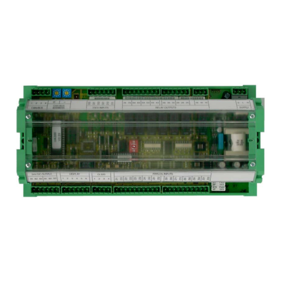
System Design of UA 300 D The UA 300 D Case Controller is a component of the new LDS System. It is based on the hardware of the UA 300 Case Controller and has been designed for application in discount stores. The controller is a package unit without optional expansion modules. - Page 8 System Design of UA 300 D Notice: Version 2.03 27. Juni 2008...
-
Page 9: Application Of Ua 300 D
For control of chiller and freezer coldrooms the UA 300 D CS/TS/AS is designed to install in a casing in the con- trol panel or in the UA 300 D CC/TC cap rail casing on the mounting plate. A digital output (24 V DC / 50 mA) is provided on the controller to connect an external signalling device. -
Page 10: Controller Types
The controller type is selected by DIP switch S3 located in the middle of the circuit board (UA 300 D xC) or on the rear of the controller (UA 300 D xS) − See Section 4.3.2 Setting Controller Type and Master/Slave Mode. -
Page 11: Function Of Ua 300 D
Temperature range 0 .. 100°C All leads running to and from the UA 300 D − especially those of the CAN bus − must be shielded! No shielding is required on sensor leads when installed exclusively inside the refrigerated display case and when external interference (for example from parallel power wires) is not to be expected. -
Page 12: Controller Function
3.2 Controller function The sections following describe the various functions of the UA 300 D for control of refrigeration points. Availabi- lity of certain controller functions depends on the controller type set on DIP switch S3 (see Section 4.3.2 Setting Controller Type). -
Page 13: Cooling (Solenoid Valve)
UR 141 Zone 1 (LT): N.C. control, i.e. cooling is ON when case controller is de−energized. E 2007 − ECKELMANN | BERLINER STRASSE 161 | 65205 WIESBADEN | FON +49(0)611 7103-0 | FAX 49(0)611 7103-133 | eckelmann.de Version 2.03 27. Juni 2008... -
Page 14: Compressor Control
Function of UA 300 D 3.2.2 Compressor control 3.2.2.1 Control by temperature according to majority (UA 111 X only) A maximum of two compressors are controlled by the base load/peak load principle. Control is made by case temperature through all supply air sensors. The peak load compressor is stopped when temperature has re- ached the setpoint (switch−off value) on the majority of the connected supply air sensors (e.g. -
Page 15: Disabling Compressors
After that time, control of the compressors is restored to the pressure switch. E 2007 − ECKELMANN | BERLINER STRASSE 161 | 65205 WIESBADEN | FON +49(0)611 7103-0 | FAX 49(0)611 7103-133 | eckelmann.de Version 2.03 27. Juni 2008... -
Page 16: On−Off Control By All Supply Air Sensors
Function of UA 300 D 3.2.2.8 On−off control by all supply air sensors Controller type: UA 111 X, UA 111 XP Control takes place through all connected first−zone supply air temperature sensors. Single−zone operation: In single−zone operation, Cooling Relay 1 and the compressor outputs are actuated. - Page 17 For example, when connecting four supply air sensors, the consecutive inputs R2.1 to R2.4 must be used. E 2007 − ECKELMANN | BERLINER STRASSE 161 | 65205 WIESBADEN | FON +49(0)611 7103-0 | FAX 49(0)611 7103-133 | eckelmann.de Version 2.03 27. Juni 2008...
-
Page 18: On−Off Control By Room Air Sensor
Function of UA 300 D 3.2.2.9 On−off control by room air sensor Controller type: UR 141 Plain on−off control: Cooling is controlled by the coldroom air temperature sensor. The cooling relay is de−energi- zed when temperature reaches the setpoint (switch−off value) on the room air sensor and is restarted with adju- stable hysteresis. -
Page 19: Continuous Running Monitoring
CAN disabling of refrigeration points by the compressor pack controller is not available on the UA 300 D. E 2007 − ECKELMANN | BERLINER STRASSE 161 | 65205 WIESBADEN | FON +49(0)611 7103-0 | FAX 49(0)611 7103-133 | eckelmann.de Version 2.03 27. Juni 2008... -
Page 20: Defrosting
Function of UA 300 D 3.2.3 Defrosting Controller type: UA 111 and UA 111 XP These two controller types do not have a defrost heater. Off−cycle defrosting is controlled by the supply air sen- sors. Controller type: UR 141 Defrosting frees the evaporator of ice forming from normal operation. Defrosting takes place either by heating the evaporator (electric heating element) or off−cycling the compressor. - Page 21 Evaporator temperature lower than defrost termination temperature With demand defrosting, defrost counter at 1 (UR 141) E 2007 − ECKELMANN | BERLINER STRASSE 161 | 65205 WIESBADEN | FON +49(0)611 7103-0 | FAX 49(0)611 7103-133 | eckelmann.de Version 2.03 27. Juni 2008...
- Page 22 Function of UA 300 D Defrost termination Defrosting can be terminated by three methods: S Defrost termination temperature obtained on corresponding evaporator temperature sensor, regardless of the set controller type S Expiration of safe defrost time S Command via CAN bus (manual command, PC software command) Defrosting is always terminated by the safe defrost time when the defrost termination temperature is set to "...
-
Page 23: Fan Control With Case Controllers
Operation of the fan relay is inverted, meaning that the contact is open when the fan is running and closed when the fan is off. E 2007 − ECKELMANN | BERLINER STRASSE 161 | 65205 WIESBADEN | FON +49(0)611 7103-0 | FAX 49(0)611 7103-133 | eckelmann.de Version 2.03 27. Juni 2008... -
Page 24: Fan Control With Coldroom Controllers
Function of UA 300 D 3.2.5 Fan control with coldroom controllers Controller type: UR 141 S LT coldrooms (low−temperature coldrooms, UR 141 Zone 1 only) The fan is normally switched ON and OFF with the cooling relay. During defrosting the fans are OFF. - Page 25 Fan 1: Fan control relay (Terminal 63/64) Fan 2: Fan control relay (Terminal 73/74) E 2007 − ECKELMANN | BERLINER STRASSE 161 | 65205 WIESBADEN | FON +49(0)611 7103-0 | FAX 49(0)611 7103-133 | eckelmann.de Version 2.03 27. Juni 2008...
-
Page 26: Door Contact
Function of UA 300 D 3.2.6 Door contact Controller type: UR 141 When working with coldrooms, 230 V inputs are each connected to a coldroom door contact. Cooling and the evaporator fan are stopped when the coldroom door is opened. -
Page 27: Lighting Control
DIGITAL OUTPUT (+24V) 24 V DC (OUT) CABINET LIGHTING DIGITAL INPUT 3 DIGITAL INPUT 1 E 2007 − ECKELMANN | BERLINER STRASSE 161 | 65205 WIESBADEN | FON +49(0)611 7103-0 | FAX 49(0)611 7103-133 | eckelmann.de Version 2.03 27. Juni 2008... -
Page 28: Archiving Operating Data
CI 320 interface. A TTY converter (available as accessory) is required for readout on a PC . Temperature recording on CI 3000 Store Computer (UA 300 D AC/AS/CC/CS) The UA 300 D records temperature at 15−minute intervals and transmits the data via the CAN bus to the CI 3000 Store Computer for archiving. -
Page 29: Installation And Startup Of Ua 300 D
S Note and observe maximum load on relay contacts (see Section 9 − Specifications). S Note that all leads running to and from the UA 300 D − especially those of the CAN bus − must be shielded and installed sufficiently clear of other leads carrying live power. Doing so will avoid faulty measurements and will protect the equipment from external interference via the analog inputs. -
Page 30: Installation
All leads running to and from the UA 300 D − especially those of the CAN bus − must be shielded! No shielding is required on sensor leads when installed exclusively inside the refrigerated display case and when external interference (for example from parallel power wires) is not to be expected. -
Page 31: Ua 300 D Xs Control Panel Mounting
Section 5. Attaching mounting braces and installation The two mounting braces enclosed with the UA 300 D xS must be attached on the left and right sides of the ca- sing for installation: 1. Push front of UA 300 D xS (2) through cutout in control panel (1). -
Page 32: Basic Parameter Settings
S Setting of Node No. (Nd.nnn = 1 .. 99) or CAN bus address by decade switches S1 and S2 (UA 300 D CC/CS/ AC/AS only). These switches are not fitted on stand−alone controllers (UA 300 D TC/TS) and an address can- not be assigned. -
Page 33: Setting The Can Bus Address
Settings made on decade switches S1 and S2 do not become effective on the UA 300 D until the controller is switched off briefly and back on! E 2007 − ECKELMANN | BERLINER STRASSE 161 | 65205 WIESBADEN | FON +49(0)611 7103-0 | FAX 49(0)611 7103-133 | eckelmann.de Version 2.03 27. Juni 2008... -
Page 34: Setting The Controller Type
The controller type can be set by Coding Switches 1 .. 3 of DIP Switch S3. Only part of the overall functions and parameters contained in the UA 300 D are available when se- lecting a specific controller type. -
Page 35: Setting Basic Parameters
Select case controller: In the selection list, select the UA 300 D case controller to be set by its Node No. (Nd.nnn = 1 to 99), either by using the cursor or typing in direct. Press the ENTER key (↵ ) to confirm. This displays the main menu of the UA 300 D case controller. - Page 36 Installation and Startup of UA 300 D Press the ESC key twice to exit Menu 1 Configuration. Choose 3 Clock − 2 Defrost Timer. Enter the relevant parameters in the following screen. 3 Clock − 2 Defrost Timer Select defrosting by external or internal defrost timer Defrost Timer Safe defrost time;...
-
Page 37: Maintenance And Battery Replacement
Undo the four screws on the front panel and remove the plastic cover by pulling up. E 2007 − ECKELMANN | BERLINER STRASSE 161 | 65205 WIESBADEN | FON +49(0)611 7103-0 | FAX 49(0)611 7103-133 | eckelmann.de Version 2.03 27. Juni 2008... -
Page 38: Replacing Battery On Ua 300 D Xs
Turn on power to the refrigeration point to restore it to operational condition. Messages or fault messages that are output on restarting the UA 300 D must be checked or cancel- led on the CI 3000 Store Computer or AL 300 Operator Terminal! 10. - Page 39 10. Controller without CAN bus (UA 300 D TC/TS/AC/AS): Date, time and automatic daylight saving change must be entered for data archiving (EU Archive). E 2007 − ECKELMANN | BERLINER STRASSE 161 | 65205 WIESBADEN | FON +49(0)611 7103-0 | FAX 49(0)611 7103-133 | eckelmann.de Version 2.03 27. Juni 2008...
- Page 40 Installation and Startup of UA 300 D Notice: Version 2.03 27. Juni 2008...
-
Page 41: Pin And Terminal Assignments Of Ua 300 D
1..8 Case part 1..8 All leads running to and from the UA 300 D − especially those of the CAN bus − must be shielded! No shielding is required on sensor leads when installed exclusively inside the refrigerated display case and when external interference (for example from parallel power wires) is not to be expected. - Page 42 Pin and Terminal Assignments of UA 300 D Relay outputs 230 V AC Controller type Relay 1 Relay 2 Relay 3 Relay 4 Relay 5 Relay 6 Relay 7 Terminal No. 15, 16, 18 25, 26, 28 35, 36, 38...
-
Page 43: Ua 300 D Xc As Case Controller
Pin and Terminal Assignments of UA 300 D 5.1 UA 300 D xC as case controller Controller type: UA 111 X, UA 111 XP – Pin assignments valid for UA 300 D CC / TC / AC GREEN GREEN GROUND... -
Page 44: Ua 300 D Xc As Coldroom Controller
Pin and Terminal Assignments of UA 300 D 5.2 UA 300 D xC as coldroom controller Controller type: UR 141 − Pin assignments valid for UA 300 D CC / TC / AC GREEN GREEN GROUND GROUND BROWN BROWN CAN-LOW... -
Page 45: Ua 300 D Xs As Case Controller
Pin and Terminal Assignments of UA 300 D 5.3 UA 300 D xS as case controller Controller type: UA 111 X, UA 111 XP − Pin assignments valid for UA 300 D CS / TS / AS GREEN GREEN GROUND... -
Page 46: Ua 300 D Xs As Coldroom Controller
Pin and Terminal Assignments of UA 300 D 5.4 UA 300 D xS as coldroom controller Controller type: UR 141 − Pin assignments valid for UA 300 D CS / TS / AS GREEN GREEN GROUND GROUND BROWN BROWN CAN-LOW... -
Page 47: Operation Of Ua 300 D
MODE key; CAPS SHIFT function for text entry Cursor keys (10) ESC key (11) Display (4 lines of 20 characters) E 2007 − ECKELMANN | BERLINER STRASSE 161 | 65205 WIESBADEN | FON +49(0)611 7103-0 | FAX 49(0)611 7103-133 | eckelmann.de Version 2.03 27. Juni 2008... -
Page 48: Menus And Screens
3 − 1 − 2. The letter or letters following indicate that one or more additional operating screens or selection lists can be opened in the screen by selecting them (?). The letters show their order in the screen. Each operating screen of the UA 300 D can be opened by entering its respective number. Menus Screens 1 Analog. - Page 49 MODE and decimal ( . ) keys to cancel entry block for the particular controller. Entry block is reactivated on exiting the operator interface for the controller. E 2007 − ECKELMANN | BERLINER STRASSE 161 | 65205 WIESBADEN | FON +49(0)611 7103-0 | FAX 49(0)611 7103-133 | eckelmann.de Version 2.03 27. Juni 2008...
- Page 50 Operation of UA 300 D Activating service mode Service mode is reserved exclusively for use by service personnel! Service mode enables the service technician to suppress the remote alarm function of the CI 3000 Store Com- puter for a limited time while carrying out maintenance of repair work.
-
Page 51: Remote Operation/Parameter Setting Of Case/Coldroom Controller
1 Actual Value 2 Setpoints 3 Clock 4 Messages 5 Archive ↓ 6 Configuration E 2007 − ECKELMANN | BERLINER STRASSE 161 | 65205 WIESBADEN | FON +49(0)611 7103-0 | FAX 49(0)611 7103-133 | eckelmann.de Version 2.03 27. Juni 2008... -
Page 52: Entering Refrigeration Point Parameters
6.4 Operation with BT 300 x Operator Interface When using the UA 300 D in stand−alone mode, the case/coldroom controller can only be operated with the BT 300 x Operator Interface. A local set−up unit can be connected to a separate interface (display). The operating options are largely the same as those provided in the remote operation menu of the AL 300 Operator Terminal or CI 3000 Store computer (see chapter 6.2). -
Page 53: Defining The Refrigeration Point
Changing the controller type resets all parameters to their default settings. E 2007 − ECKELMANN | BERLINER STRASSE 161 | 65205 WIESBADEN | FON +49(0)611 7103-0 | FAX 49(0)611 7103-133 | eckelmann.de Version 2.03 27. Juni 2008... - Page 54 Operation of UA 300 D Notice: Version 2.03 27. Juni 2008...
-
Page 55: Menu Structure Ua 300 D
DEFROST 1A Zone 2A Altern. 2−2−4 DEFROST 2A −−− Not used with this controller type E 2007 − ECKELMANN | BERLINER STRASSE 161 | 65205 WIESBADEN | FON +49(0)611 7103-0 | FAX 49(0)611 7103-133 | eckelmann.de Version 2.03 27. Juni 2008... - Page 56 Menu structure UA 300 D Controller type UA 111 X Level 1 Level 2 Level 3 Screen No. Screen Name Setpoints SETPOINTS Alarm 2−4 ALARM Zone 1 2−4−1 ALARM 1 Zone 2 2−4−2 ALARM 2 Zone 1A Altern. 2−4−3 ALARM 1A Zone 2A Altern.
-
Page 57: Menu 0 Main Menu
Continue to Screen 1−8: Menu item is shown only when two−zone operation is set 8 Defrost Zone 2 (Screen 6−1). E 2007 − ECKELMANN | BERLINER STRASSE 161 | 65205 WIESBADEN | FON +49(0)611 7103-0 | FAX 49(0)611 7103-133 | eckelmann.de Version 2.03 27. Juni 2008... - Page 58 Menu structure UA 300 D Controller type UA 111 X S Screen 1−1 Temp. Sensor TEMPERATUR POS:XXXXX Current supply air temperature Input Z11/Z12 Temp. R2.1 XXX °C Current return air temperature Input Z21/Z22 Temp. R4.1 XXX °C Current supply air temperature Input Z31/Z32 Temp.
- Page 59 XXX °C Day and time of last defrost cycle started Last DefrstWe XX hh:mm E 2007 − ECKELMANN | BERLINER STRASSE 161 | 65205 WIESBADEN | FON +49(0)611 7103-0 | FAX 49(0)611 7103-133 | eckelmann.de Version 2.03 27. Juni 2008...
-
Page 60: Menu 2 Setpoints
Menu structure UA 300 D Controller type UA 111 X 7.1.3 Menu 2 Setpoints SETPOINTS POS: XXXXX Continue to Screen 2−1; Special case: Move to Screen 2−1−1 when single−zone operation is 1 Cooling set (Screen 6−1) and setpoint toggle is disabled (Screen 3−3) Continue to Screen 2−2;... - Page 61 POS: XXXXX Defrost termination temperature setpoint −−, 5..20 5 °C Def. End. Tmp. XX °C E 2007 − ECKELMANN | BERLINER STRASSE 161 | 65205 WIESBADEN | FON +49(0)611 7103-0 | FAX 49(0)611 7103-133 | eckelmann.de Version 2.03 27. Juni 2008...
- Page 62 Menu structure UA 300 D Controller type UA 111 X S Screen 2−2−3 Zone 1A Altern. Entry Default DEFROST 1A POS: XXXXX Defrost termination temperature setpoint −−, 5..20 8 °C Def. End. Tmp. XX °C S Screen 2−2−4 Zone 2A Altern.
- Page 63 Delay C1 OFF xxx s Stop delay Compressor 2 0..250 Delay C2 OFF xxx s E 2007 − ECKELMANN | BERLINER STRASSE 161 | 65205 WIESBADEN | FON +49(0)611 7103-0 | FAX 49(0)611 7103-133 | eckelmann.de Version 2.03 27. Juni 2008...
-
Page 64: Menu 3 Clock
Menu structure UA 300 D Controller type UA 111 X 7.1.4 Menu 3 Clock CLOCK POS: XXXXX Continue to Screen 3−1 1 Current Time Continue to Screen 3−2 2 Defrost timer Continue to Screen 3−3 3 Toggle Setpoints S Screen 3−1 Current Time Time default is set by the time master (CI 3000, AL 300) when CAN bus is connected. -
Page 65: Menu 4 Messages
End of Fault n (only when Fault n terminated) dd.mm.yy hh:mm S Screen 4−2 Acknowlegde messages Alarms Cancelled! is displayed. E 2007 − ECKELMANN | BERLINER STRASSE 161 | 65205 WIESBADEN | FON +49(0)611 7103-0 | FAX 49(0)611 7103-133 | eckelmann.de Version 2.03 27. Juni 2008... -
Page 66: Menu 5 Archive
Menu structure UA 300 D Controller type UA 111 X S Screen 4−3 Delete messages Entry MESSAGES POS: XXXXX ↵, ESC Safety prompt for deleting messages; Delete ! press ESC to go back after cancelling messages Are you sure ? YES: ↵... - Page 67 Software Vers.: XXXX Device No. of case/coldroom controller − Serial No.: XXXXXX (from EEPROM) E 2007 − ECKELMANN | BERLINER STRASSE 161 | 65205 WIESBADEN | FON +49(0)611 7103-0 | FAX 49(0)611 7103-133 | eckelmann.de Version 2.03 27. Juni 2008...
- Page 68 Menu structure UA 300 D Controller type UA 111 X S Screen 6−2−2 Temp. Display Entry Default DISPLAY POS: XXXXX Offset for temperature display −10..10 Offset XX K S Screen 6−2−3 Alarm Delay Entry Default ALARMDELAY POS: XXXXX Sensor break alarm delay 0..30...
- Page 69 Default LANGUAGE POS: XXXXX √ ↵ √ Deutsch ↵ English ↵ Francais ↵ Cesky E 2007 − ECKELMANN | BERLINER STRASSE 161 | 65205 WIESBADEN | FON +49(0)611 7103-0 | FAX 49(0)611 7103-133 | eckelmann.de Version 2.03 27. Juni 2008...
-
Page 70: Controller Type Ua 111 Xp − Menu Tree
Menu structure UA 300 D Controller type UA 111 XP 7.2 Controller type UA 111 XP − Menu tree 1: ON 2: OFF 3: OFF 4: OFF 5: OFF Level 1 Level 2 Level 3 Screen No. Screen Name Main menu REFR: PT. - Page 71 230 V Inputs 6−2−4 230V INPUT Sensor Type 6−2−5 SENSORS Cooling 6−3 COOLING Language 6−4 LANGUAGE E 2007 − ECKELMANN | BERLINER STRASSE 161 | 65205 WIESBADEN | FON +49(0)611 7103-0 | FAX 49(0)611 7103-133 | eckelmann.de Version 2.03 27. Juni 2008...
-
Page 72: Menu 0 Main Menu
Menu structure UA 300 D Controller type UA 111 XP 7.2.1 Menu 0 Main menu REFR. PT. POS: XXXXX Continue to Screen 1 1 Actual Values Continue to Screen 2 2 Setpoints Continue to Screen 3 3 Clock Continue to Screen 4... - Page 73 Current ON/OFF status of Compressor 2 output Terminals 53/54 Compressor 2 Current ON/OFF status of Compressor 3 output Terminals 63/64 Compressor 3 E 2007 − ECKELMANN | BERLINER STRASSE 161 | 65205 WIESBADEN | FON +49(0)611 7103-0 | FAX 49(0)611 7103-133 | eckelmann.de Version 2.03 27. Juni 2008...
-
Page 74: Menu 2 Setpoints
Menu structure UA 300 D Controller type UA 111 XP S Screen 1−7 Cooling Zone 2 COOLING 2 POS: XXXXX Current ON/OFF status of cooling Zone 2 Terminals 35/36/38 Cooling Cooling relay on time during last day (00:00 − 24:00 hours) - Page 75 Continue to Screen 2−2−4; shown only when two−zone operation is set (Screen 6−1) and only 4 Zone 2A Altern. when setpoint toggle is enabled (Screen 3−3) E 2007 − ECKELMANN | BERLINER STRASSE 161 | 65205 WIESBADEN | FON +49(0)611 7103-0 | FAX 49(0)611 7103-133 | eckelmann.de Version 2.03 27. Juni 2008...
- Page 76 Menu structure UA 300 D Controller type UA 111 XP S Screen 2−2−1 Zone 1 Entry Default DEFROST 1 POS: XXXXX Defrost termination temperature setpoint −−, 5..20 8 °C Def. End. Tmp. XX °C S Screen 2−2−2 Zone 2 Entry...
- Page 77 Continue to Screen 2−5−1, Setpoints 1 Setpoints Continue to Screen 2−5−2, Setpoint Toggle 2 Setpoint toogle E 2007 − ECKELMANN | BERLINER STRASSE 161 | 65205 WIESBADEN | FON +49(0)611 7103-0 | FAX 49(0)611 7103-133 | eckelmann.de Version 2.03 27. Juni 2008...
- Page 78 Menu structure UA 300 D Controller type UA 111 XP S Screen 2−5−1 Setpoints (Compressor) Entry Default COMPRESSOR POS: XXXXX ↑, ↓, Enable Compressor 1 Enable C1 (ON/OFF) ↑, ↓, Enable Compressor 2 Enable C2 (ON/OFF) ↑, ↓, Enable Compressor 3...
-
Page 79: Menu 3 Clock
(ON/OFF) *) Parameter automatically set to ON for safe defrost time at first start. E 2007 − ECKELMANN | BERLINER STRASSE 161 | 65205 WIESBADEN | FON +49(0)611 7103-0 | FAX 49(0)611 7103-133 | eckelmann.de Version 2.03 27. Juni 2008... -
Page 80: Menu 4 Messages
Menu structure UA 300 D Controller type UA 111 XP S Screen 3−3 Toggle Setpoints Entry Default TOGGLE POS: XXXXX Setpoint toggle status (OFF/ON) of alternative set of setpo- Status ints (setpoint toggle) ↑, ↓, Setpoint toggle via input D21/22 (EXT), internal (INT) or Toggle Setp. -
Page 81: Menu 5 Archive
2 Controller Continue to Screen 6−3 3 Cooling Continue to Screen 6−4 4 Language E 2007 − ECKELMANN | BERLINER STRASSE 161 | 65205 WIESBADEN | FON +49(0)611 7103-0 | FAX 49(0)611 7103-133 | eckelmann.de Version 2.03 27. Juni 2008... - Page 82 Cheese Counter 2 and CC2. The name is entered in the screens of the CI 3000 Store Computer or AL 300 Operator Terminal. Direct entry cannot be made in the UA 300 D screens displayed on ope- rator terminals. The name also cannot be entered with the BT 300 x Operator Interface.
- Page 83 In failure of required sensors, the solenoid is actuated 0..100 Emergency Op. XX % to adjust to the set opening in % E 2007 − ECKELMANN | BERLINER STRASSE 161 | 65205 WIESBADEN | FON +49(0)611 7103-0 | FAX 49(0)611 7103-133 | eckelmann.de Version 2.03 27. Juni 2008...
- Page 84 Menu structure UA 300 D Controller type UA 111 XP S Screen 6−4 Language Entry Default LANGUAGE POS: XXXXX √ ↵ √ Deutsch ↵ English ↵ Francais ↵ Cesky Version 2.03 27. Juni 2008...
-
Page 85: Controller Type Ur 141 − Menu Tree
ALARM 2 Zone 1A Altern. 2−4−3 ALARM 1A Zone 2A Altern. 2−4−4 ALARM 2A E 2007 − ECKELMANN | BERLINER STRASSE 161 | 65205 WIESBADEN | FON +49(0)611 7103-0 | FAX 49(0)611 7103-133 | eckelmann.de Version 2.03 27. Juni 2008... - Page 86 Menu structure UA 300 D Controller type UR 141 Level 1 Level 2 Level 3 Screen No. Screen Name Clock CLOCK Current Time 3−1 CLOCK Defrost timer 3−2 DEFROST TIMER Setpoints toggle 3−3 TOGGLE Messages MESSAGES View 4−1 MESSAGES Acknowledge 4−2...
-
Page 87: Menu 0 Main Menu
Temp. R4.4 XXX °C Current evaporator sensor temperature Input Z01/Z02 Temp. R1.4 XXX °C E 2007 − ECKELMANN | BERLINER STRASSE 161 | 65205 WIESBADEN | FON +49(0)611 7103-0 | FAX 49(0)611 7103-133 | eckelmann.de Version 2.03 27. Juni 2008... - Page 88 Menu structure UA 300 D Controller type UR 141 S Screen 1−2 Cooling Zone 1 COOLING 1 POS: XXXXX Current ON/OFF status of cooling Zone 1 Terminals 25/26/28 Cooling Cooling relay on time during last day (00:00 − 24:00 hours)
- Page 89 Current temperature on evaporator sensor R1.3 Temp. R1.3 XXX °C Fan delay Fan Delay XX °C E 2007 − ECKELMANN | BERLINER STRASSE 161 | 65205 WIESBADEN | FON +49(0)611 7103-0 | FAX 49(0)611 7103-133 | eckelmann.de Version 2.03 27. Juni 2008...
-
Page 90: Menu 2 Setpoints
Menu structure UA 300 D Controller type UR 141 7.3.3 Menu 2 Setpoints SETPOINTS POS: XXXXX Continue to Screen 2−1; Special case: when single−zone operation is set (Screen 6−1) and 1 Cooling setpoint toggle is disabled (Screen 3−3) Continue to Screen 2−1−1 Continue to Screen 2−2;... - Page 91 XX °C Waiting time setpoint 0..15 Wait Time Drip time setpoint 0..15 Drip Time E 2007 − ECKELMANN | BERLINER STRASSE 161 | 65205 WIESBADEN | FON +49(0)611 7103-0 | FAX 49(0)611 7103-133 | eckelmann.de Version 2.03 27. Juni 2008...
- Page 92 Menu structure UA 300 D Controller type UR 141 S Screen 2−2−3 Zone 1A Altern. Entry Default DEFROST 1A POS: XXXXX Counting rate setpoint 0..15 Counting Rate Defrost counter − Defrost Counter Defrost termination temperature setpoint −−, −10..30 12 °C Def.
- Page 93 Low Temperature alarm is gene- rated S Screen 2−4−3 Zone 1A Altern. E 2007 − ECKELMANN | BERLINER STRASSE 161 | 65205 WIESBADEN | FON +49(0)611 7103-0 | FAX 49(0)611 7103-133 | eckelmann.de Version 2.03 27. Juni 2008...
-
Page 94: Menu 3 Clock
Menu structure UA 300 D Controller type UR 141 Entry Default ALARM 1A POS: XXXXX High temperature setpoint at which High Temperature −30..30 −12 °C High Temp Setp XX °C alarm is generated Low temperature setpoint (difference below temperature −−, 0..6 Low Temp Setp. - Page 95 A toggle time will only be obeyed when a matched pair of on and off times is set as a parameter. E 2007 − ECKELMANN | BERLINER STRASSE 161 | 65205 WIESBADEN | FON +49(0)611 7103-0 | FAX 49(0)611 7103-133 | eckelmann.de Version 2.03 27. Juni 2008...
-
Page 96: Menu 4 Messages
Menu structure UA 300 D Controller type UR 141 7.3.5 Menu 4 Messages MESSAGES POS: XXXXX Continue to Screen 4−1 Show message log 1 View Messages in message log are cancelled; alarms are cancelled after being shown: press 2 Acknowledge ESC to go back Continue to Screen 4−3... -
Page 97: Menu 6 Configuration
Number of temperature zones: Temp. Zones Single−zone operation/ or numbers Two−zone operation (1, 2) E 2007 − ECKELMANN | BERLINER STRASSE 161 | 65205 WIESBADEN | FON +49(0)611 7103-0 | FAX 49(0)611 7103-133 | eckelmann.de Version 2.03 27. Juni 2008... - Page 98 Cheese Counter 2 and CC2. The name is entered in the screens of the CI 3000 Store Computer or AL 300 Operator Terminal. Direct entry cannot be made in the UA 300 D screens displayed on ope- rator terminals. The name also cannot be entered with the BT 300 x Operator Interface.
- Page 99 Default LANGUAGE POS: XXXXX √ ↵ √ Deutsch ↵ English ↵ Francais ↵ Cesky E 2007 − ECKELMANN | BERLINER STRASSE 161 | 65205 WIESBADEN | FON +49(0)611 7103-0 | FAX 49(0)611 7103-133 | eckelmann.de Version 2.03 27. Juni 2008...
- Page 100 Menu structure UA 300 D Controller type UR 141 Notice: Version 2.03 27. Juni 2008...
-
Page 101: Alarms And Messages Of Ua 300 D
Close door, check door switch or connec- droom controller UR 141 only. ting cable E 2007 − ECKELMANN | BERLINER STRASSE 161 | 65205 WIESBADEN | FON +49(0)611 7103-0 | FAX 49(0)611 7103-133 | eckelmann.de Version 2.03 27. Juni 2008... -
Page 102: Alarms
Alarms and Messages of UA 300 D Message Cause Correction Messages Sensor Fault Sensor disconnected, short circuiting of sensor. Tem- Check connecting cable, perature on sensor outside set measuring range. Re- check cable screening, quired or optional sensors are monitored when detec- replace sensors affected ted by controller through sensor scan. -
Page 103: Messages
- Change of setpoint - Manual shutdown - Defrosting terminated by safe defrost time E 2007 − ECKELMANN | BERLINER STRASSE 161 | 65205 WIESBADEN | FON +49(0)611 7103-0 | FAX 49(0)611 7103-133 | eckelmann.de Version 2.03 27. Juni 2008... -
Page 104: Transient Alarms And Messages
Alarms and Messages of UA 300 D 8.3 Transient alarms and messages Transient alarms are one−time event alarms and are not time stamped for send time. As a result, transient alarms are not deleted automatically after the event and must be cancelled manually. This applies regardless of the setting made for Selfholding (Menu 6−2−3). -
Page 105: Specifications Of Ua 300 D
IP20 CE conformity Conforming to EU Directive 73/23/EEG (Low Voltage Directive) 89/336/EEG (EMC Directive) E 2007 − ECKELMANN | BERLINER STRASSE 161 | 65205 WIESBADEN | FON +49(0)611 7103-0 | FAX 49(0)611 7103-133 | eckelmann.de Version 2.03 27. Juni 2008... -
Page 106: Mechanical Data
Specifications of UA 300 D 9.2 Mechanical data 9.2.1 DIN rail mounting of UA 300 D xC C stands for "In Cabinet", meaning DIN rail mounting. View without connector set Connector set with cable Version 2.03 27. Juni 2008... -
Page 107: Panelmounting Of Ua 300 D Xs
S stands for "Switchbox", meaning control panel mounting 109,5 +0,8 (1): Control panel (2): Panel cutout E 2007 − ECKELMANN | BERLINER STRASSE 161 | 65205 WIESBADEN | FON +49(0)611 7103-0 | FAX 49(0)611 7103-133 | eckelmann.de Version 2.03 27. Juni 2008... - Page 108 Specifications of UA 300 D Notice: Version 2.03 27. Juni 2008...
Need help?
Do you have a question about the UA 300 D and is the answer not in the manual?
Questions and answers