
Subscribe to Our Youtube Channel
Related Manuals for ECKELMANN UA 410 L Case Controller


Summary of Contents for ECKELMANN UA 410 L Case Controller
- Page 1 Operating instruction UA 410 L Case Controller Temperature Data Logging Controller - Version V1.50 Firmware V1.50 - Doku 2.0 06. April 2016...
- Page 2 All rights to any use whatever, utilisation, further development, forwarding and creation of copies remain with the Eckelmann AG company. In particular, neither the contract partners of Eckelmann AG nor other users have the right to distribute or mar ket the IT programs/program parts or modified or edited versions without express written permission. To some extent, names of products/goods or designations are protected for the respective manufacturer (registered trademarks etc.);...
-
Page 3: Table Of Contents
Conventions ..............Explanation of 'General Instructions' . - Page 4 Temperature display BT 30 ..........4.4.1 Offset for temperature display .
- Page 5 6.12 Terminal assignment of the USB interface ....... . . 6.13 Terminal assignment of the CI 320/TTY interface .
- Page 6 Alarms and Messages of UA 410 L ........10.1 Alarm signaling and monitoring .
-
Page 7: Conventions
Conventions Explanation of 'General Instructions' A general instruction is composed of two elements: 1. A pictogram of a hand at the side of the page as well as 2. The actual text: For example: Further information on the device's degree of protection is contained in the chapter ”Technical Data”. Explanation of 'Safety Instructions and Hazard Warnings' Safety instructions or hazard warnings are composed of four elements: 1. -
Page 8: Warning Signs And Symbols Employed
Warning Signs and Symbols Employed Explanation of the warning signs and symbols employed for the safety instructions and hazard warnings in this documentation: S Attention symbol - general hazard warning 1. Hazard warning The attention symbol indicates all safety instructions in this operating and service manual, which, if not observed, could result in danger to life and limb. -
Page 9: Safety Instructions
Safety instructions Safety instructions The safety regulations, codes and notes contained in this section must definitely be observed and complied with at all times. During repairs on the entire E*LDS system, the accident prevention regu lations and general safety instructions must be observed. Important information (safety instructions and hazard warnings) are indicated by corresponding symbols (see page 1 of the chapter ”Conven... -
Page 10: Disclaimer In The Event Of Non-Compliance
Safety instructions Work on electrical equipment may only be undertaken by authorized and duly trained personnel (as defined by DIN/VDE 0105 and IEC364) with full observance of the currently valid regulations contained in the following: - VDE Regulations - Local safety codes - Intended use see chapter 1.3 - BGV A3 - Five Safety Rules... -
Page 11: Intended Use
Safety instructions 1.3 Intended use This control system may only be used for the purpose for which it is intended: The UA 410 L control system has been designed for use as a data logging controller in commercial and indus trial refrigeration systems with the intended functional scope as described in these operating instructions, and it is to be used under the environmental conditions in these instructions. -
Page 12: Electrostatic Sensitive Devices (Esds)
Safety instructions 1.5 Electrostatic sensitive devices (ESDs) Electronic components and assemblies (e.g. printed circuit boards) are vulnerable to electrostatic discharge. Regulations for handling and working with electrostatic sensitive devices must definitely be observed and complied with, see also section 1.5.1! All electrostatic sensitive devices (ESDs) are identified by the warning sign illustrated. -
Page 13: System Design Of Ua 410 L
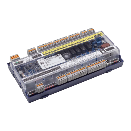
System Design of UA 410 L System Design of UA 410 L Figure: UA 410 L AC - full configuration 2.1 Application The UA 410 L AC temperature recording controller is based on the UA 400 hardware and has been developed for use as a temperature recording controller of up to 10 temperature measurement points. -
Page 14: Hardware
System Design of UA 410 L 2.2 Hardware The temperature recording controller is housed in a plastic casing for DIN rail mounting and does not require any further optional expansion modules. Up to 99 case controllers can be used within the E*LDS system. As required, a BT 300 x Operator Interface and up to 4 BT 30 Temperature Displays can be connected. -
Page 15: New Features Compared To Previous Versions
System Design of UA 410 L Real-time clock Battery-backed, lithium cell For precise details of the UA 410 L AC see chapter 3.1. The connection and terminal configurations are described in the chapter Connection and Terminal Configuration. 2.3 New features compared to previous versions Version 1.50 S New hardware platform UA 410 L - blue main board... - Page 16 System Design of UA 410 L Version 1.50 S New hardware platform UA 410 L - for DIN rail mounting S Optimised labelling strip S Differences in the complete hardware (UA 410 L AC, see photo) compared to UA 300 L AC: - 2 analogue inputs 4..20 mA Currently reserve for future applications - 2 analogue outputs 0..
-
Page 17: Application Of Ua 410 L
Application of UA 410 L Application of UA 410 L 3.1 Versions The UA 410 L is only available in the AC variant and has the following features: UA 410 L AC For DIN rail mounting For integration in the CAN bus of the E*LDS system Replacement controller for UA 300 L Replacement controller for the LDS1 system (connection to the LDS1 system proceeds via the CI320 interface) -
Page 18: Controller Type
Application of UA 410 L 3.2 Controller type Ttemperature recording controller UA 410 L Case Controller: Controller type Application UA 410 L Temperature Data Logging Controller for maximum 10 temperature sensors (with the option of on-off control/defrosting of five independent refrigeration points for the first five sensors). -
Page 19: Function Of Ua 410 L
Function of UA 410 L Function of UA 410 L Parameters mentioned in this section are described in the Menu Structure section. It will normally not be necessary to change the default settings of these parameters. Parameters that do not allow changing are termed fixed parameters below. -
Page 20: Required And Optional Sensors
Function of UA 410 L 4.2 Required and optional sensors On the standard UA 400 controllers the Sensor Scan function determines the number of sensors connected. This enables sensors that are not connected to be removed from sensor break monitoring. However, the following procedure is required with the UA 410 L Temperature Data Logging Controller: If specific sensors are deactivated for the alarm signalling, the sensor priority must be configured accordingly. -
Page 21: Temperature Control (With Recording)
Function of UA 410 L Cooling relay operation N.O. control, i.e. cooling is OFF when the case controller is de-energized. Cooling (not the controller itself) can be stopped via Digital Input 1 (Terminals D11/12). Control is suppressed when a 230 V AC signal is applied to this input. Cooling is active when the input is not connected or not active. -
Page 22: Temperature Recording
Function of UA 410 L 4.3.1.3 Temperature recording Refrigeration point controller Rx.6 Rx.1 Rx.7 Rx.2 Rx.8 Rx.3 Rx.9 Rx.4 Rx.0 Rx.5 Rx.1 .. Rx.0: 10 temperature sensors for temperature recording A separate sensor name can be assigned to each sensor for better identification of the measuring location. -
Page 23: Defrosting
Function of UA 410 L 4.3.2 Defrosting Defrosting (available only with the first five temperature sensors Rx.1 .. Rx.5) frees the evaporator of ice forming from normal operation. Defrosting always takes place either by off-cycling the compressor. During defrosting, temperature control of the refrigeration point is inactivated. Refrigeration point controller Rx.1... -
Page 24: Monitoring
Function of UA 410 L Defrost termination Defrosting can be terminated by two methods: ‐ Defrost termination temperature obtained on corresponding temperature sensor ‐ Expiration of safe defrost time Defrosting is always terminated by the safe defrost time when the defrost termination temperature is set to ”--”, in which case no ”Defrost Termination By Time”... -
Page 25: Archiving Operating Data
Function of UA 410 L 4.3.4 Archiving operating data 4.3.4.1 Temperature recording to EU Regulation 37/2005 If the controller is connected to the CAN bus, only the sensors Rx.1 and Rx.2 in the system centre / store computer are archived. This archiving can cover a full year. Local temperature recording Temperature is recorded at 15-minute intervals in the internal flash memory. - Page 26 Function of UA 410 L CI 4x00: All 10 temperature sensors are supported in system centres. CI 3x00: Whether the version in use supports this function can be checked in the System Centre / Store Com puter User Guide. Store Computers of all versions are always capable of archiving two temperatures. With all, the recording interval is 15 minutes and data is archived for a period of one year.
-
Page 27: Real Time Clock
Function of UA 410 L Values 3 to 10 of the EU Archive Zone parameter are to be used only for recording in conjunction with the Temperature Data Logging Controller itself. Only values 1 or 2 may be used for recording in conjunction with a case/EU archiving must also be active on the System Centre / Store Computer in order to commence recording (see System Centre / Store Computer operating instruction). -
Page 28: Temperature Display Bt 30
Function of UA 410 L 4.4 Temperature display BT 30 4.4.1 Offset for temperature display An offset (parameter Offset in Menu 2) can be applied to temperature values as a means of compensating dif ferences between readings on thermometers in the refrigerated display case and on the case controller. This offset affects the complete functionality (cooling, defrosting, recording, etc.) for which the sen... - Page 29 Function of UA 410 L Before connecting to the case/coldroom controller, all BT 30 Temperature Displays must be addressed by means of the exposed leads (see illustration): Leads Konfiguration BT 30 Address 1 Address 2 Address 3 Address 4 Green Closed Open Closed...
- Page 30 Function of UA 410 L Notice: Firmware V1.50 - Doku 2.0 06. April 2016...
-
Page 31: Installation And Startup Of Ua 410 L
Installation and Startup of UA 410 L Installation and Startup of UA 410 L Important safety instructions! Before the installation and commissioning of the controller, chapter 1 should be carefully read in its entirety and all safety instructions and hazard warnings observed. The controller should only be used with compatible versions of the PC software LDSWin, otherwise the range of functions could be restricted. -
Page 32: Mounting On The Din Rail
Installation and Startup of UA 410 L 5.1.1.1 Mounting on the DIN rail Step 1: The two retaining springs on the underside of the device are to be pulled out using a flat-bladed screw driver until they click into place. In order to carry out the assembly/disassembly there must be a distance of at least 8 mm between the bottom of the case controller and the next component (e.g. -
Page 33: Disassembling From The Din Rail
Installation and Startup of UA 410 L 5.1.1.2 Disassembling from the DIN rail Warning - hazardous electrical voltage! Danger of electric shock! When disassembling the safety instructions and work safety instructions in chapter 1 must be observed. All connectors may only be connected and disconnected when power is off. -
Page 34: Handling Of The Spring Terminals
Installation and Startup of UA 410 L 5.1.2 Handling of the spring terminals All terminal connections of the controller are implemented with grey mating connectors with spring terminals (push-in spring connection). The connectors have the following characteristics: S Conductors with cross sections between 0.25 and 2.5 mm² can be used. S All mating connectors are coded and any reverse polarity is therefore ruled out. -
Page 35: Basic Configuration
Installation and Startup of UA 410 L 5.2 Basic configuration The following basic settings on the hardware and software side must be made during the commissioning of the case controller: Settings before connection of the power supply S Set CAN bus address (Nd.nnn = 1 to 99) by Decade Switches S1 and S2. S Set controller type and Mster/Slave mode on DIP Switch S3. -
Page 36: Setting Can Bus Address
Installation and Startup of UA 410 L 5.3 Setting CAN bus address CAN bus address (Nd.nnn = 1 to 99) are set by Decade Switches S1 and S2. For all case controllers installed in refrigerated cases, a unique CAN bus address must first be set at the two selector switches (S1, S2) before commissioning. -
Page 37: Setting The Controller Type
Installation and Startup of UA 410 L 5.4 Setting the controller type Caution: data loss! All parameters are reset to their factory settings if the controller type is changed or due to a first start (see chapter 5.8)! Setting controller type The required controller type is set via the DIP switch S3 by adjusting the coding switches 1..8 with a thin screw... -
Page 38: Terminal Assignment For 230 V Ac Power Supply
Installation and Startup of UA 410 L 5.5 Terminal assignment for 230 V AC power supply Warning - hazardous electrical voltage! Danger of electric shock! BEFORE and AFTER connection it must checked that the 230 V AC supply cable is off load! The power supply cable is connected to the case controller using the right hand terminal block PE/L/N: 230 V AC 11 VA... -
Page 39: Status Leds
Installation and Startup of UA 410 L 5.5.1 Status LEDs Warning - hazardous electrical voltage! Danger of electric shock! The device is never to be operated without its casing. Before opening the casing the equipment must be switched to zero potential. CAN-BUS BATTERY LED12... -
Page 40: Basic Configuration Of The Controller
Installation and Startup of UA 410 L 5.6 Basic configuration of the controller The lock-down must previously be deactivated on the higher level controller (system centre / store computer or operator terminal) so that configuration settings can be made on the controller. Deactivating the input lock-down A. - Page 41 Installation and Startup of UA 410 L Basic configuration of the controller - select refrigeration point (Menu 6-1) The menus shown below only provide the overview; the display can be different for certain controller ty pes. Details are described in the "Menu Structure" chapter. 6 Configuration - 1 Refrigeration Point REFR.
- Page 42 Installation and Startup of UA 410 L Menu 6 Configuration - select 2 Select Controller 6 Configuration - 2 Controller CONTROLLER POS: XXX Type, serial number and master-slave (ON/OFF) 1 Type and Version Select temperature sensor type 2 Sensor Type Exit Configuration: Press the ESC key twice to exit the menu.
-
Page 43: Naming Of The Controller
Installation and Startup of UA 410 L 5.6.1 Naming of the controller The following parameters are available for naming the controller: - refrigeration point name (19 characters, can be freely edited) - refrigeration point position (5 characters, can be freely edited) The controller can be named using the system centre, store computer, operator terminal or the PC software LDSWin. -
Page 44: Maintenance And Battery Replacement
Installation and Startup of UA 410 L 5.9 Maintenance and battery replacement Only UA 410 L AC The case controller contains a backup battery of Type CR 2450 N, 3V Lithium. The case controller must be re moved from the system to change the battery. During this time, control and monitoring of the refrigeration point are disabled. - Page 45 Installation and Startup of UA 410 L Do not touch the new battery with metal pliers, as it might be short-circuited and destroyed: - wipe the new battery with a clean, dry cloth, - do not touch the contact faces on the edges of the new battery. Never dispose of this product with other household waste.
-
Page 46: Firmware Update
Installation and Startup of UA 410 L 5.10 Firmware Update The case controller is supplied with the current firmware, ready for operation. Future software versions can be loaded into the case controller as required by means of a firmware update, and thus updated. A software update is only to be carried out by trained staff or factory-side by the manufacturer. - Page 47 Installation and Startup of UA 410 L Step 1: Install the software 1. Before first connecting the controller to the PC the installation program ”Firmware_Up loader_Setup_vxx.exe” must be executed once. Please follow the instructions given by the installation assistant. In the following window the components to be installed can be selected. Now select the target folder: Following installation the PC must be restarted: Firmware V1.50 - Doku 2.0 06.
- Page 48 Installation and Startup of UA 410 L Step 2: Changing the position of DIP switch S3 and connecting the controller The original position of the coding switches 1..8 of the DIP switch S3 must be documented! 1. In order to carry out the firmware update all coding switches 1..8 of DIP switch S3 must be set to ON. 1 2 3 4 5 6 7 8 After the firmware update has been carried out all the coding switches 1..8 of the DIP switch S3 must be returned to their original position, see chapter 5.10.2...
-
Page 49: Uploading The Firmware Update
PC. Step 1: Under ”Start / Programs / ECKELMANN / Firmware Uploader” start the program ”KGL Firmware Uploader”. The following window opens: Select language, and then select the path to the folder for the new firmware (binary file). - Page 50 Installation and Startup of UA 410 L Step 3: Press the button ”Find Controller” in order to locate the controller. Then press the button ”Update Firmware” in order to start the firmware upload. Step 4: Following the start of the firmware upload a confirmation window appears, confirm this with ”YES”. Step 5: Following the successful firmware update the program can be closed.
-
Page 51: Rectification Of Driver Problems
Installation and Startup of UA 410 L 5.10.3 Rectification of driver problems Should the driver installation be incomplete or should the controller have been accidentally connected to the PC before the execution of the installation program, then the following instructions will provide you with information on how the problem can be rectified: Windows XP/Vista: If the controller was accidentally connected to the PC before the execution of the installer, then the driver must be updated in the system control. - Page 52 Installation and Startup of UA 410 L Notice: Firmware V1.50 - Doku 2.0 06. April 2016...
-
Page 53: Pin And Terminal Assignments Of Ua 410 L
Pin and Terminal Assignments of UA 410 L Pin and Terminal Assignments of UA 410 L 6.1 Terminal diagram Power Analog Digital Relay Outputs supply Outputs Inputs CAN bus 0..10 V 230 V AC 230 V AC 230 V AC 6(3) A 11 VA CAN-BUS... -
Page 54: Terminal Assignment Of The 230 V Ac Power Supply
Pin and Terminal Assignments of UA 410 L 6.2 Terminal assignment of the 230 V AC power supply Warning - hazardous electrical voltage! Danger of electric shock! BEFORE and AFTER connection it must checked that the 230 V AC supply cable is off load! 230 V AC 11 VA CAN-BUS... -
Page 55: Terminal Assignment Of The 230 V Ac Relay Outputs
Pin and Terminal Assignments of UA 410 L 6.3 Terminal assignment of the 230 V AC relay outputs Warning - hazardous electrical voltage! Danger of electric shock! BEFORE and AFTER connection it must checked that the 230 V AC relay outputs are off load! Low voltage and safety extra-low voltage must not be applied together at the relay outputs. -
Page 56: Mode Of Operation Of The Relay And Transistor Outputs
Pin and Terminal Assignments of UA 410 L 6.4 Mode of operation of the relay and transistor outputs The table shows operation of the outputs for the separate controller types. Relay outputs 230 V AC Transistor outputs 24 V DC/50 mA Controller type Cooling Alarm... -
Page 57: Terminal Assignment Of The 0
Pin and Terminal Assignments of UA 410 L If 230 V AC voltage is present at digital input, the associated red LED lights, see chapter 5.5.1 Status LEDs for details. 6.6 Terminal assignment of the 0..10 V analogue outputs This functionality is currently not used! Warning - hazardous electrical voltage! Connecting mains power to the analogue outputs will lead to the destruction of the controller! -
Page 58: Terminal Assignment Of The Can Bus
Pin and Terminal Assignments of UA 410 L 6.7 Terminal assignment of the CAN bus Warning - hazardous electrical voltage! If mains voltage is connected to the CAN bus terminals, this will result in the destruction of all components connected to the CAN bus! Leads running of the CAN bus must be shielded (cable type: LiYCY)! As a general rule, care should be taken to ensure that signal leads and leads carrying a supply voltage are routed through separate cable channels. -
Page 59: Terminal Assignment Of The 24 V Dc Transistor Outputs
Pin and Terminal Assignments of UA 410 L 6.8 Terminal assignment of the 24 V DC transistor outputs Warning - hazardous electrical voltage! Connecting mains power to the transistor outputs will lead to the destruction of the controller! Destruction of the transistor outputs! Due to the capacity of the transistor outputs of a max. -
Page 60: Terminal Assignment Of The Display Interface
Pin and Terminal Assignments of UA 410 L 6.9 Terminal assignment of the DISPLAY interface DISPLAY BT 300 BT 30 An operator interface of the BT 300 series (e.g. for service purposes) and up to four BT 30 temperature displays can be connected to the DISPLAY interface. -
Page 61: Terminal Assignment Of The Analogue Inputs Of Temperature Sensors
Pin and Terminal Assignments of UA 410 L 6.11 Terminal assignment of the analogue inputs of temperature sensors Warning - hazardous electrical voltage! Connecting mains power to the analogue inputs will lead to the destruction of the controller! Malfunctions due to interference sources! All leads running to and from the case controller must be shielded (cable type: LiYCY)! No shielding is required on sensor leads when installed exclusively inside the refrigerated display case and when external interference (for example from parallel power wires) is not to be expected (see operating instruction “Basics and General Safety and Connection... -
Page 62: Terminal Assignment Of The Usb Interface
Pin and Terminal Assignments of UA 410 L 6.12 Terminal assignment of the USB interface The USB interface facilitates the uploading of a firmware update. Furthermore, in future (currently not available) it will be possible to read out the operating data of the case controller via a PC equipped with LDSWin. USB-LED DISPLAY Typ B... -
Page 63: Operation Of Ua 410 L
Operation of UA 410 L Operation of UA 410 L 7.1 Operation possibilities The controller provides menus and screens for the display and adjustment of values. However, no operation for this is provided on the controller itself. The actual operation of these menus is performed externally using the following possibilities: S Local operation with a BT 300 x operator interface: The operation is performed directly on-site at the con... -
Page 64: Local Operation With A Bt 300 X Operator Interface
Operation of UA 410 L 7.2 Local operation with a BT 300 x operator interface BT 300 x RESET DISPLAY An operator interface in the BT 300 series is connected locally via the DISPLAY interface. Thereby, the con troller can be operated standalone as shown or also connected to the CAN bus. The operation here largely corresponds to the possibilities as described for the system centre, the store com... -
Page 65: Remote Control Via A Terminal
Operation of UA 410 L 7.3 Remote control via a terminal Further details for the operation of a system centre, store computer or operator terminal can be found in their operating manuals. For the remote control of a controller, it makes no difference whether this is done with a system centre (A), a store computer or with an operator terminal (B) as the user interfaces on the terminals are almost identical and the same functions are available. -
Page 66: Menus And Operating Screens
Operation of UA 410 L 7.3.1 Menus and operating screens If the system centre, store computer or operator terminal remain locked down, settings on the con troller are read-only. Changes and inputs are not possible. However, if any parametrisation is required, the lock-down for the input must be removed first, see chapter 7.3.3. - Page 67 Operation of UA 410 L Menus A menu can contain up to ten menu items (0 .. 9; 0 for menu item 10). After the selection of a menu item using the cursor buttons (↑) and (↓) and by tapping the ENTER button (↵) or by tapping the buttons 0..9), other sub menus or operating screens are displayed.
-
Page 68: Calling The Controller Menu Via Remote Control
Operation of UA 410 L Entering text In fields that allow text entry, text can also be entered by the alphanumeric keypad. Repeatedly press the nu meric keys to generate letters. Press the ENTER key (↵) to confirm the entered value or text. Letter/Character PQRS PQRS... -
Page 69: System Centre Ci 4X00
Operation of UA 410 L 7.3.2.1 System Centre CI 4x00 The terminal for remote control of the controller (Menu 2-2 or Menu 4-2) is called in the system centre as fol lows: Step 1: Tap "2 - System overview" or "4 - Configuration" in the main menu. If "2"... -
Page 70: Deactivating The Input Lock-Down
Operation of UA 410 L 7.3.3 Deactivating the input lock-down Operation via system centre, store computer or operator terminal is only possible for controllers with CAN bus connection; the removal of the lock-down is then applicable for all components in the CAN bus system. The lock-down is automatically reactivated 15 minutes after the last button tap. -
Page 71: Activating Service Mode
Operation of UA 410 L 7.3.4 Activating service mode For repair and maintenance work, service personnel can deactivate the remote alarm function of the system centre and of the store computer for a limited period using the service mode. The activation of the service mode must only be carried out by service personnel. If there are still pending alarms (with the priority 1..2) after the time of the Service Mode has elapsed, the audible warning devices and the alarm relays are activated and the alarms are forwarded using the automatic transmission of alarms. - Page 72 Operation of UA 410 L Notice: Firmware V1.50 - Doku 2.0 06. April 2016...
-
Page 73: Menu Structure Of Ua 410 L
Menu Structure of UA 410 L Menu Structure of UA 410 L The sensor wanted must first be selected to open the main menu of a temperature sensor (Rx.1 .. Rx0). REFR. PT. POS: XXX Select 1st temperature sensor Rx.1 1 Temp. -
Page 74: Menu 0 Main Menu
Menu Structure of UA 410 L 8.2 Menu 0 Main menu Temp. Rx.y POS: XXXXX Move to menu 1 1 Actual Value Move to menu 2 2 Setpoints Move to menu 3 3 Clock Move to menu 4 4 Messages Move to menu 5 5 Archive Move to menu 6... -
Page 75: Menu 2 Setpoints
Menu Structure of UA 410 L 8.4 Menu 2 Setpoints Entry Default SETPOINTS POS: XXXXX High temperature setpoint -50..100 10°C High Temp: xxx°C Low temperature setpoint -50..100 -5°C Low Temp: xxx°C High or low temperature delay 0..150 Delay: ↑, ↓, Priority: High or low temperature alarm priority --, 0..2... -
Page 76: Menu 4 Messages
Menu Structure of UA 410 L S Menu 3-1 Current Time When connected to the CAN bus, the default time is provided via the time master (system centre / store computer, operator terminal). Any entry made will then be overwritten by the default value. Entry Default CLOCK... -
Page 77: Menu 5 Archive
Menu Structure of UA 410 L S Menu 4-1 View messages MESSAGES POS: XXXXX Fault 1 message text Error Message 1: Start of Fault 1 dd.mm.yy hh:mm ON/OFF End of Fault 1 (only when Fault 1 terminated) dd.mm.yy hh:mm ON/OFF Fault n message text Error Message n: Start of Fault n... -
Page 78: Menu 6 Configuration
Menu Structure of UA 410 L Following selection, the following menu will appear: Temp. Rx.y POS: XXXXX Time of archiving Record 1 dd.mm.yy hh:mm Status and temperature of Zone 1, see Note *) Zone 1: x °C *) Status ab covers following states of the refrigeration point. Display will be ”-- ” if state is not active. Status R = Cooling (with sensors Rx.1 .. - Page 79 Menu Structure of UA 410 L S Menu 6-2 Controller CONTROLLER POS: XXXXX Move to menu 6-2-1 1 Type and Version Move to menu 6-2-5 2 Sensor type S Menu 6-2-1 Type and Version Entry Default VERSION POS: XXXXX Set by DIP switch S3 UA400L CTRLR.
- Page 80 Menu Structure of UA 410 L Notice: Firmware V1.50 - Doku 2.0 06. April 2016...
-
Page 81: Decommissioning And Disposal
The scope of our delivery is designated as a component exclusively for further processing. As a consequence of this fact, Eckelmann AG does not undertake any measures for the taking back or munici pal recycling of this product as it is not supplied directly to the free market. - Page 82 Decommissioning and disposal Notice: Firmware V1.50 - Doku 2.0 06. April 2016...
-
Page 83: Alarms And Messages Of Ua 410 L
Alarms and Messages of UA 410 L 10 Alarms and Messages of UA 410 L Message Cause Correction Hardware faults EEPROM Fault Component for saving configuration defective or confi Save parameters in LDSWin software, guration data in EEPROM implausible. perform first start if necessary and load parameters from LDSWin. -
Page 84: Alarm Signaling And Monitoring
Alarms and Messages of UA 410 L 10.1 Alarm signaling and monitoring 10.1.1 High or low temperature alarm High or low temperature is alarmed when temperature rises or falls to the alarm setpoint and the set delay has expired. °C OVER TEMPERATURE TEMPERATURE REFERENCE VALUE... -
Page 85: Sensor Break Alarm
Alarms and Messages of UA 410 L 10.1.4 Sensor break alarm Alarm is generated after the set delay expires (Menu 6-2-1) if the controller detects breakage or short circuit on a sensor. This delay time is global for the controller and applies equally for all sensors. Sensor break alarm is only generated when priority of the sensor concerned is set to a value other than ”-”. -
Page 86: Transient Alarms And Messages
Alarms and Messages of UA 410 L 10.2.1 Transient alarms and messages Transient alarms are one-time event alarms and are not time stamped for send time. As a result, transient alarms are not deleted automatically after the event and must be cancelled manually. This applies regardless of the setting made for Selfholding (Menu 6-2-3). -
Page 87: Specifications Of Ua 410 L
Specifications of UA 410 L 11 Specifications of UA 410 L 11.1 Electrical data Warning - hazardous electrical voltage! Danger of electric shock! Overvoltage category III (test voltage 4,0 kV) / pollution degree 2: All device connections designed for use with 230 V AC supply voltage must be connected to the same phase conductor. - Page 88 Specifications of UA 410 L UA 410 L AC Fieldbus port CAN bus, floating Data port DISPLAY: BT 300x Operator terminal and up to 4 BT 30 Temperature displays CI320 (TTY) Communication with the PC software for reading off the operating data USB interface For firmware update (in future it will be possible to connect a notebook (PC) to this interface for the direct parameterisation via LDSWin)
- Page 89 Specifications of UA 410 L Supplement to standard DIN EN 12830 for temperature recorders (UA 410 L AC with L243 temperature sensor) Metrological characteristics Accuracy class Maximum permissible error +/- 1 K Resolution internal: 0.1 °C / display and recording: 1 K Recording interval 15 min.
-
Page 90: Mechanical Data Of The Controller
Specifications of UA 410 L 11.2 Mechanical data of the controller DIN rail mounting of UA 410 L AC (C stands for ”In Cabinet”, meaning DIN rail mounting.) Gegenstecker mit Kabel Darstellung ohne Gegenstecker Connector set with cable View without connector set Set de connecteur s avec... -
Page 91: Order Numbers And Accessories Of Ua 410 L
Order numbers and accessories of UA 410 L 12 Order numbers and accessories of UA 410 L 12.1 Case Controller Type Description Order number UA 410 L AC For DIN rail mounting, with CAN bus, real time clock, KGLUA4L016 internal archive, analog inputs and analog outputs 12.2 Accessories Accessories Description... - Page 92 Order numbers and accessories of UA 410 L Notice: Firmware V1.50 - Doku 2.0 06. April 2016...
Need help?
Do you have a question about the UA 410 L Case Controller and is the answer not in the manual?
Questions and answers