Table of Contents

Subscribe to Our Youtube Channel
Related Manuals for ECKELMANN Case Controller UA 4 E Series


Summary of Contents for ECKELMANN Case Controller UA 4 E Series
- Page 1 Operating instruction Case Controller UA 4xx E Controller for electronic expansion valves (EEV) The series UA 4xx E includes the following expansion stages: UA 400 E CC / UA 401 E CC / UA 410 E AC Firmware V3.13 21.04.2021 Docu 3.8...
- Page 2 Copyright: All rights to any use whatever, utilisation, further development, forwarding and creation of copies remain with the Eckelmann AG company. In particular, neither the contract partners of Eckelmann AG nor other users have the right to distribute or market the IT programs/program parts or modified or edited versions without express written permission.
-
Page 3: Table Of Contents
Table of Contents Conventions............................10 Warning signs, symbols and text formatting used in this manual..........10 Explanation of text formatting ......................11 Safety instructions ..........................12 Disclaimer in the event of non-compliance ..................13 Personnel requirements, requirements on staff ................13 Intended use ............................14 Five safety rules according to DGUV Regulation 3................15 Electrostatic-sensitive components and control components (ESD) ..........16 2.5.1 ESD - Rules for handling and working ....................16... - Page 4 5.7.4 Continuous temperature control by coldroom sensor ................46 5.7.5 Continuous temperature monitoring using refrigerant temperature sensor..........48 5.7.6 On-off control............................50 5.7.7 Superheat control ...........................51 5.7.8 Connection of pressure transmitters / humidity sensors ................54 5.7.9 Sending and receiving the analogue values via CAN bus ..............55 5.7.10 Humidity control............................56 5.7.11...
- Page 5 5.10.8 Heating circuit - contr. type UR 141 TE, UR 141 NE in single-zone operation ........97 5.11 Digital inputs............................98 5.11.1 Setpoint toggle (day/night operation) .....................99 5.11.2 Manual shutdown ..........................100 5.11.3 Automatic on/off............................100 5.11.4 Door contact ............................102 5.11.5 Registration of external alarms (e.g. CO2 alarm).................103 5.12 Function of the analogue outputs 0..10 V.
- Page 6 6.6.2 Installing firmware update ........................146 6.6.2.1 Update for controller with 8-pole DIP switch ..................147 6.6.2.2 Update for controller with 9-pole DIP switch ..................151 6.6.3 Rectification of driver problems ......................154 Pin and Terminal Assignments of UA 4xx E ..................156 Terminal diagram..........................156 Terminal assignment of the 230 V AC power supply ..............159 Terminal assignment of the 230 V AC relay outputs...............160 Mode of operation of the relay and transistor outputs..............162...
- Page 7 9.1.2 Menu 1 Actual Values UA 121 E......................191 9.1.3 Menu 2 Setpoints UA 121 E .........................197 9.1.4 Menu 3 Clock UA 121 E ........................206 9.1.5 Menu 4 Messages UA 121 E........................210 9.1.6 Menu 5 Archive UA 121 E ........................211 9.1.7 Menu 6 Configuration UA 121 E......................212 Contr.
- Page 8 Contr. Type UK 100 E - Menu tree .....................387 9.6.1 Main Menu UK 100 E ...........................389 9.6.2 Menu 1 Actual Values UK 100 E ......................390 9.6.3 Menu 2 Setpoints UK 100 E .........................395 9.6.4 Menu 3 Clock UK 100 E ........................399 9.6.5 Menu 4 Messages UK 100 E........................402 9.6.6...
- Page 9 Technical Data of UA 4xx E .......................462 12.1 Electrical data .............................462 12.2 Mechanical Data ..........................464 12.3 Mechanical data of the temperature sensor L243 / 5K3A1.............464 Order numbers and accessories of UA 4xx E .................465 13.1 Case Controller...........................465 13.2 Components ............................465 INTERNE INCUDES - NICHT ZUR VERÖFFENTLICHUNG BESTIMMT...........466 14.1 Kältemittel EN - Menü...
-
Page 10: Conventions
1 Conventions 1.1 Warning signs, symbols and text formatting used in this manual Explanation of the warning signs, symbols and text formatting used in this operating and service manual: • DANGER DANGER Instructions with this symbol and/or the signal word DANGER warn the user of situations that will cause severe injury or death if the specified instructions are not observed! * •... -
Page 11: Explanation Of Text Formatting
A general instruction consists of two elements: The symbol with text (including NOTICE, if applicable) and the text of the instruction: For example: NOTICE The current operating manual is available online from the E°EDP (Eckelmann ° Electronic Documentation Platform) at www.eckelmann.de/elds. Firmware V3.13 21.04.2021 11/466... -
Page 12: Safety Instructions
2 Safety instructions This operating manual is part of the device. It must be kept in the vicinity of the controller as well as for future use so that it can be consulted when required. The operating manual must be available to the operating and maintenance personnel at all times in order to avoid operating errors. -
Page 13: Disclaimer In The Event Of Non-Compliance
WARNING Warning of damage to goods! In our experience, the transmission of fault messages is not yet functional during the putting into service (no internet connection, no telephone line installed, etc.). It is strongly recommended in such cases to monitor the controller via the CAN bus using a system centre, a store computer or an operator terminal and to enable the transmission of fault messages, for example using a GSM modem via a mobile telephone system. -
Page 14: Intended Use
2.3 Intended use This control system may only be used for the purpose for which it is intended: The UA 401 E CC / UA 400 E CC / UA 410 E AC control system has been designed for use as case controller in commercial and industrial refrigeration systems with the intended functional scope as described in these operating instructions, and it is to be used under the environmental conditions in these instructions. Read the safety instructions and the instructions for installation and putting into service, operation and maintenance. THEN start the commissioning and/or operation of the machine / system. The safety and functionality of the machine / system are only guaranteed for this intended application. -
Page 15: Five Safety Rules According To Dguv Regulation 3
2.4 Five safety rules according to DGUV Regulation 3 The following rules must be strictly observed! 1. Disconnect: The entire system to be worked on must be disconnected from the power supply at all poles. DANGER Warning of dangerous electrical voltage! Warning of dangerous electrical voltage! Danger of electric shock! Beware of a possible external power supply! BEFORE connecting and disconnecting it must be checked that no voltage is present at the controller! Connections/plug connectors of the device may... -
Page 16: Electrostatic-Sensitive Components And Control Components (Esd)
2.6 Abbreviations used • DGUV Regulation 3 - Accident Prevention Regulation for Electrical Systems and Equipment (previously: BGV A3 - Employer’s Liability Association Regulation for Occupational Health and Safety) • DIN Deutsches Institut für Normung e.V. (German Standardisation Institute) • EDP: Electronic Documentation Platform of Eckelmann AG • ESD Electrostatic-Sensitive Device • ESD Electro-static discharge (Electro Sensitive Devices) • IEC International Electric Committee •... -
Page 17: System Design Of Ua 4Xx E
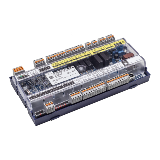
3 System Design of UA 4xx E Figure: UA 410 E AC - full configuration 3.1 Application The use of the case controller UA 4xx E for electronic expansion valves provides decisive advantages thanks to a reduced pressure difference between the high and low pressure sides, low superheat at the evaporator as well as constant conditions for the goods and evaporator thanks to continuous regulation. -
Page 18: Hardware
In order to fully utilise its performance features, the case controller is typically connected to the CAN bus, using which it communicates with further control and monitoring components across the entire network. Intelligent data exchange with the following system components takes place via the CAN bus: •... - Page 19 Mounting variants UA 401 E CC UA 400 E CC UA 410 E AC (complete design) = terminals not mounted For details, see chapter Terminal diagram. Interfaces • • • CAN bus, communication in the E•LDS system • • • DISPLAY - Connection for BT 300 x operator interface and up to four BT 30 temperature displays •...
-
Page 20: Application Of Ua 4Xx E
4 Application of UA 4xx E 4.1 Versions Distinguishing features of the UA 4xx E case controller for DIN rail mounting; for further details, see chapter Hardware. UA 401 E CC UA 400 E CC * UA 410 E AC * (complete design) Mounting variants = terminals not mounted... - Page 21 * Special feature: The UA 400 E CC / UA 410 E AC controllers are available in two device generations; the DIP switch provides a quick distinguishing feature: • 1st generation - Characteristic 8-position DIP switch: UA 400 E CC / UA 410 E AC: since 2011 •...
-
Page 22: Controller Types
4.2 Controller types The selection of the controller type determines the regulation and control functions as well as the basic settings. The following controller types and their areas of application are available in the case controller for refrigeration points with pulse-width modulated clocked or continuous expansion valves (motor valves): Controller type Applications Case controller UA 121 E... - Page 23 For more details, see chapter Operation UA 4xx Firmware V3.13 21.04.2021 23/466...
-
Page 24: Updating Firmware
4.3 Updating firmware The case controller is supplied with the current firmware, ready for operation. Future software versions can be loaded into the case controller as required by means of a firmware update, and thus updated. ATTENTION Danger data loss! In some cases a change of firmware version can lead to the loss of all the setpoints in the case controller. -
Page 25: Function Ua 4Xx E
5 Function UA 4xx E The range of functions provided below describes the complete design UA 410 E AC in two-zone operation; for more details, see chapter Versions. Functions and parameters that are not available in single-zone operation are (not always) marked "Only two-zone operation"... -
Page 26: Restart - Restart Of The Controller
Disconnect controller from the power supply for safety reasons (see also chapter Setting the controller type and other functions). Reset DIP switch S3 to the noted starting position. Switch on controller again. The settings of the controller have been reset to the factory settings. 5.1.2 Restart - restart of the controller For a restart, the device is restarted with all configured parameters and the CAN bus address set on the decade switches S1 and S2. -
Page 27: Temperature Zones
5.2 Temperature zones The case controller supports up to 2 temperature zones, which can be configured via the "Temperaturzonen" parameter (menu 6-1). The two UA 400 E CC / UA 410 E AC case controllers support single-zone and two- zone operation. The UA 401 E CC variant only supports one temperature zone. Single-zone operation - UA 400 E CC / UA 401 E CC / UA 410 E AC •... - Page 28 Two-zone operation - only UA 400 E CC / UA 410 E AC • two temperature zones • 2 pilot cases In two-zone operation, the temperature and superheat are controlled separately for each refrigerated case. In addition to the conventional end of defrosting, there is the possibility of returning the two refrigerated cases to the cooling operation together after a defrost.
-
Page 29: Can Bus Mode
5.3 CAN bus mode The controller is integrated in the CAN bus in this operating mode. The remote control via a terminal generally performed via the system centre, which also takes care of the alarm management. In addition, the suction gas temperature t of the pack controller belonging to the refrigeration circuit via the CAN bus is used to determine superheat. -
Page 30: Standalone Operation
5.4 Standalone operation Only UA 400 E / UA 410 E In this operating mode, the controller operates standalone, operation is local, see chapter Local operation with a BT 300 x Operator Interface. In addition, this Alarm relay is required for alarm signalling, otherwise no alarm path is available. In contrast to this CAN bus mode, the suction gas temperature t for determining superheat is... -
Page 31: Standalone Operation Using Activated Local Pressure Transmitter
5.4.2 Standalone operation using activated local pressure transmitter Only UA 410 E AC If this operating mode is used, the suction gas temperature t for determination of the superheat is calculated using the suction gas temperature t coming from the local pressure transmitter and the value of the evaporator outlet sensor R6.x;... -
Page 32: Selection Of The Sensor Type
5.5 Selection of the sensor type The case controller uses 2-wire NTC temperature sensors for the regulation. For the variants UA 400 E CC / UA 401 E CC / UA 410 E AC, 5 sensors (Z1..Z5 for single-zone operation) can be connected, for the variants UA 400 E CC / UA 410 E AC, 10 sensors (Z1..Z5 / Z6..Z10) can be connected for two-zone operation). -
Page 33: Necessary And Optional Sensors
5.5.1 Necessary and optional sensors Depending on the controller type and the operating mode, there are necessary and optional sensors for the case controller. A sensor scan is performed automatically during the first start of the controller. The number of scanned sensors can be checked in the menu (6-1) or with the LDSWin PC software. - Page 34 For details about the pin assignment, see chapter Terminal assignment of the analogue inputs for temperature sensors. Firmware V3.13 21.04.2021 34/466...
-
Page 35: Description Of Controller Functions
Explanation for the sensor designation Legend: Ry.x y = type of the sensor Defrost sensor Supply air sensor Return air sensor / room air sensor / refrigerant temperature sensor (UK 100 E) Evaporator inlet sensor Evaporator outlet sensor x = case Zone 1 / Zone 2 Error message in the event of sensor fault An alarm (sensor fault) is always triggered if necessary sensors are not attached. -
Page 36: Cooling
5.7 Cooling 5.7.1 Temperature control The regulation is performed via the opening degree of the E-valve (see chapter Control of the expansion valves). The regulation is carried out separately for each temperature zone using its own controller parameter set, whereby the temperature and superheat regulation is carried out by one PID controller for each. It is automatically decided whether the refrigeration point temperature controller (evaporator section filling mode) or the superheat controller (maximum evaporator filling mode) is active. -
Page 37: Control Of The Expansion Valves
5.7.2 Control of the expansion valves The output of the opening degree for controlling the two electronic expansion valves of zone 1 and zone 2 is provided at the factory via the pulsing (PWM - pulse width modulation) of the two semiconductor relays EEV1 and EEV2 and the two analogue outputs AO1 and AO2 (only UA 410 E AC). - Page 38 Only UA 410 E AC Continuous motor expansion valves The opening degree is also output simultaneously via the two analogue outputs 0..10 V (corresponds to 0..100%) for the control of continuous motor expansion valves (factory setting): The following must be observed when using the analogue outputs: The opening degree at the two analogue outputs is only output if the coding switch 6 of the DIP switch S3 is also set to OFF (factory setting; for details, see chapter Control of continuous motor expansion valves.
- Page 39 Continuous motor expansion valves with enable relay Some continuous expansion valves require an enable via an additional signal input. For example, the required signal - can be generated via a time relay using the pulsed semiconductor relay EEV1 or EEV2 (holding time t of the time relay 10 sec. < t < 30 sec.) or - it can be realised using the "enable relay" function; the parameter "Freigaberel." (menu 6-3) must be configured to "ON"...
-
Page 40: Control Of Continuous Motor Expansion Valves
5.7.2.1 Control of continuous motor expansion valves Only UA 410 E AC The opening degree is output at the two opening degree analogue outputs using a 0..10 V signal for the control of continuous motor expansion valves (factory setting; for details, see Functions of the analogue outputs 0..10 •... -
Page 41: Enable Relays For Motor Expansion Valves
5.7.2.2 Enable relays for motor expansion valves Only UA 410 E AC This function is used to control continuous motor expansion valves via the analogue outputs 0..10 V (terminals 29/30 (AO1) and terminals 31/32 (AO2)). If the motor expansion valves used require wiring of their enable input, or if an additional solenoid valve should be used for shutdown for safety reasons, the two semiconductor relays EEV1 and EEV2 (terminals 23/24 and 33/34) can be used for this. Furthermore, the enable relays can support the implementation of standalone ... - Page 42 ATTENTION Danger due to liquid refrigerant on the suction side of the compressor! The superheat control is only performed via the analogue outputs! If the wiring is incorrect, there is a risk of liquid refrigerant escaping from the evaporator! When implementing a standalone application with compressor control on the case side, a protective circuit such as a HP monitor and application-specific, external safety technology must be installed! The compressors are “only enabled” by the case controller.
-
Page 43: Continuous Temperature Control By Supply And Return Air Temperature
5.7.3 Continuous temperature control by supply and return air temperature Controller types UA 121 E, UA 131 E, UA 141 E Control is made by two temperature sensors (supply air or return air sensor of pilot case). Cooling can take place in single-zone or two-zone mode. In single-zone mode, sensors Ry.1 act on both relays 1 and 2 of the ... - Page 44 In two-zone mode, sensor Ry.1 acts on Relay 1 and Ry.2 acts on Relay 2. R2.1: Supply air sensor (Terminal Z11/12) R4.1: Return air sensor (Terminal Z21/22) R5.1: Evaporator inlet sensor (Terminal Z41/42) R6.1: Evaporator outlet sensor (Terminal Z51/52) R2.2: Supply air sensor (Terminal Z61/62) R4.2: Return air sensor (Terminal Z71/72) R5.2: Evaporator inlet sensor (Terminal Z91/92) R6.2: Evaporator outlet sensor (Terminal Z01/02) Expansion valve 1: Relay for expansion valve 1 (Terminal 23/24) Expansion valve 2: Relay for expansion valve 2 (Terminal 33/34)
- Page 45 Supply air/return air mode The supply air setpoint is toggled as a function of return air temperature as follows: Example 1: Return air < Return air - 2K: Actual Setpoint Supply air temperature is controlled to return air setpoint. Example 2: Return air - 2K <...
-
Page 46: Continuous Temperature Control By Coldroom Sensor
5.7.4 Continuous temperature control by coldroom sensor Controller types UR 141 TE, UR 141 NE Cooling is controlled according to temperature measured on the cold room air sensor. When cold room air temperature equals the current setpoint, opening duration of the expansion valve is reduced to the time required to maintain the current state. - Page 47 In two-zone mode, Ry.1 sensors act on Relay 1 and Ry.2 on Relay 2. R4.1: Cold room air sensor (Terminal Z21/22) R5.1: Evaporator inlet sensor (Terminal Z41/42) R6.1: Evaporator outlet sensor (Terminal Z51/52) R4.2: Cold room air sensor (Terminal Z71/72) R5.2: Evaporator inlet sensor (Terminal Z91/92) R6.2: Evaporator outlet sensor (Terminal Z01/02) Expansion valve 1: Relay for expansion valve 1 (Terminal 23/24)
-
Page 48: Continuous Temperature Monitoring Using Refrigerant Temperature Sensor
5.7.5 Continuous temperature monitoring using refrigerant temperature sensor Controller type UK 100 E or KR 160 E The cooling is controlled according to the temperature of the refrigerant temperature sensor.. If the refrigerant temperature value reaches the current setpoint, the opening time of the expansion valve is reduced to the value required to maintain the condition reached. - Page 49 In two-zone operation (tandem, sensors Ry.1 have an effect on relay 1 and Ry.2 on relay 2. R4.1: Refrigerant temperature sensor (terminals Z21/22) R5.1: Evaporator input sensor (terminals Z41/42) R6.1:Evaporator output sensor (terminals Z51/52) R4.2: Refrigerant temperature sensor (terminals Z71/72) R5.2: Evaporator input sensor (terminals Z91/92) R6.2:Evaporator output sensor (terminals Z01/02) E-valve 1: Relay for expansion valve 1 (terminals 23/24)
-
Page 50: On-Off Control
5.7.6 On-off control The on-off control can be selected via a parameter instead of the continuous temperature control and can be parametrised separately for each zone. ATTENTION The operation of the superheat regulation with two temperature sensors R5.x/R6.x (without local pressure transmitter and without transmission of the suction pressure from the pack controller via the CAN bus) and the on-off control has not been fully tested. -
Page 51: Superheat Control
5.7.7 Superheat control Superheat control works parallel with temperature control. As required, control is made to the defined superheatsetpoint. Superheat control works in two modes that can be toggled by a parameter (offset). Operating mode “Stand Alone”: With activated local pressure transmitter (see chapter On-off control): Calculating differences in the temperature measured at the local pressure transmitter (suction gas temperature, based on the measured pressure with the assistance of the set coolant table) and the temperature ... - Page 52 Superheat regulation In order to determine the superheat there are a number of channels which the controller can use to calculate the temperature corresponding to the suction pressure. The following priorities apply: local Z1: The local pressure transmitter is used for the regulation in zone 1 and zone 2, see menu 6-2-6! One MUST be in stand-alone operation. When using the function “toZ2ctl” (see parameter “Fct. AIN2” in menu 6-2-6) the value t0 local Z1 is used for the regulation of zone 1 and the value t local Z2 for zone 2.
- Page 53 Relative Superheat In order to improve the superheat regulation it is possible to change from a preset to an adaptive superheat setpoint. The adapative superheat setpoint can move freely between upper and lower limits at a preset maximum speed. The controller calculates on a cyclical basis the most suitable superheat setpoint for the current state.
-
Page 54: Connection Of Pressure Transmitters / Humidity Sensors
5.7.8 Connection of pressure transmitters / humidity sensors Only UA 410 E AC In order to measure the suction pressure at the case controller, a low pressure transmitter 0..10 bar can be connected. The electrical connection of the pressure transmitter, i.e. humidity sensor, is carried out according to the same principles as those familiar from the pack controller. -
Page 55: Sending And Receiving The Analogue Values Via Can Bus
5.7.9 Sending and receiving the analogue values via CAN bus It is possible to receive analogue values (t0, humidity, tc) from a remote case controller, and conversely to send them to as many case controllers within the system as desired. This serves to reduce the number of pressure transmitters installed in the system, thus leading to a reduction in costs. The necessary parameterisation is carried out in menu 6-2-6. Sending the analogue values By setting the parameter AIN1/2 Send CAN the corresponding analogue value is made available within the CAN bus and can be received by other case controllers. -
Page 56: Humidity Control
2. Configuration of the three case controllers (group members) Menu 6-2-6: Parameter AIN1 activ set to “No” (analogue input 1 is not used) Parameter Refrig.Z 1 (selection of the refrigerant)* Parameter LP Z1 min. (smallest pressure value for pressure monitoring at 4 mA)* Parameter LP Z1 max. (largest pressure value for pressure monitoring at 20 mA)* Parameter AIN1 Send CAN set to “No” (this is therefore a group member) Parameter AIN1 Rcv. CAN set to “15” (CAN bus address of the remote case controller) Parameter AIN1 Rcv. AIN1 set to “1”... - Page 57 Room air sensor Humidity Humidity R4.1 setpoint actual value exceeded within the hysteresis Exceeds room setpoint Cooling Heating Cooling Heating Cooling Heating + hysteresis + 1 K OFF * OFF * Exceeds room setpoint Cooling Heating Cooling Heating Cooling Heating + hysteresis OFF * ON / OFF...
-
Page 58: Regulation According To Tc / High Pressure
5.7.11 Regulation according to tc / high pressure Only UA 410 E AC and only controller type UK 100 E or KR 160 E With the controller type UK 100 E or the controller type KR 160 E, control can be performed both via the subcooler outlet temperature / cascade outlet temperature as well as via t . The following settings must be ... -
Page 59: Dynamic Determination Of The Tc Setpoint
5.7.12 Dynamic determination of the tc setpoint Only UA 410 E AC and only controller type UK 100 E or KR 160 E The t setpoint can be dynamically calculated depending on the difference of t actual value from t . -
Page 60: Fixed Opening Degree In The Pump Down / Injection Phase
5.7.13 Fixed opening degree in the pump down / injection phase There are 3 events, after which the controller performs an initialisation cycle in which the opening degree is preset. These are only relevant in the context of superheat control via R5.x / R6.x (e.g. no suction gas pressure transmission t from the pack controller). -
Page 61: Limiting The Opening Degree
5.7.14 Limiting the Opening Degree An upper limit to the opening degree output by the case controller can be set using this function. This opening degree is never greater than the maximum value set using the parameter Maximum OD (menu 6-2-7). ... -
Page 62: Run Time Limitation / Continuous Run Monitoring Of The Regulation
5.7.16 Run time limitation / continuous run monitoring of the regulation All controller types except UK 100 E and KR 160 E Mainly for multidecks, there are negative effects if the case goes into continuous running, e.g. in the case of difficult environmental conditions. -
Page 63: Forced Cooling (Except Uk 100 E, Kr 160 E)
5.7.17 Forced cooling (except UK 100 E, KR 160 E) The pack controller (e.g. VS 3010) can initiate a forced cooling for the case controller via CAN bus. The case controller performs continuous cooling for as long as forced cooling is active. Firmware V3.13 21.04.2021 63/466... -
Page 64: Heating Circuit Control
5.7.18 Heating circuit control Only UA 400 E CC / UA 410 E AC and only UR 141 NE / UR 141 TE As an alternative to the second temperature zone, the temperature can be controlled in cold rooms with a supplementary heating circuit. Heating circuit control is plain on-off control. The heating circuit control relay cuts ... -
Page 65: Emergency Op
5.7.19 Emergency Op. In the event of a failure of the temperature measurement, i.e. the superheat regulation, refrigeration continues to operate at an emergency opening degree. This emergency opening degree is calculated from the average value of the opening degree of the last day (24 hours) and has an upper limit defined by a configurable parameter. -
Page 66: Operation With Up To Four Return Air Sensors - Only Ua 131 E Ls
5.7.20 Operation with up to four return air sensors - only UA 131 E LS Only controller type UA 131 E LS Using the parameter Temperat. R4.3 or Temperat. R4.4 (menu 6-3 Return air sensors), the operation of up to four return air sensors (in one temperature zone) can be enabled, see table. Number of return air sensors Temperature zones UA 401 E CC... -
Page 67: Defrosting In General
5.8.2 Defrosting in general The defrosting counteracts the icing-up of the evaporator during the normal controlled operation. The evaporator is defrosted using additional heating of the evaporator (electric heater) or off-cycle defrosting. Thereby, the temperature control of the refrigeration point is switched off. Defrosting functions differently in single-zone or two-zone operation: In two-zone operation, R1.1 determines the defrost termination of the first zone and R1.2 determines the defrost termination of the second zone. - Page 68 In two-zone operation, the sensors R1.1 and R1.2 are used for the defrosting. R1.1: Defrost sensor (terminals Z31/Z32) R1.2: Defrost sensor (terminals Z81/Z82) E-valve 1: Relay for expansion valve 1 (terminals 23/24) E-valve 2: Relay for expansion valve 2 (terminals 33/34) Defrost heater 1: Relay for defrost heater 1 (terminals 43/44) Defrost heater 2: Relay for defrost heater 2 (terminals 53/54) Assignment of the sensors to the defrost relays...
- Page 69 Start of the defrosting The defrosting can be initiated in 4 ways: • Using the internal clock (except UK 100 E or KR 160 E) A further defrost cannot be started until the safe defrost time (defrost parameters) has elapsed, even if the defrost has already been terminated via the evaporator temperatures. If possible, the defrost time should not be between 02:00 and 03:00 in order to avoid problems with missing or doubled defrost during the changeover between summer and winter time.
- Page 70 Separate defrost start according to the two temperature zones using the internal defrost timer Usually, it is sufficient if the defrost is started simultaneously for both zones. A separate defrost for each zone can be performed if an application requires this. Further parameters are available for this. In the E*LDS system, defrost time means the time when defrosting starts.
- Page 71 Wait time (not for controller type UA 141 E) A wait time between switching off the cooling and switching on the defrost heater can be set for initiating the defrost. This prevents the defrost heater from being operated at the same time as the evacuation of the evaporator.
- Page 72 In the case of discharge gas defrosting (hotgas defrosting), the 2nd defrost stage must not be parametrised otherwise the 2nd defrost relay is not activated, as is generally desired with discharge gas defrosting. Storage compartment for service counters (controller type UA 141 E) The Inverted Defrost relay (terminals 63/64, function reversed) can be used, for example, to interrupt the cooling of a storage compartment.
-
Page 73: Discharge Gas Defrosting (Hot Gas Defrosting)
5.8.3 Discharge gas defrosting (hot gas defrosting) Discharge gas defrosting involves feeding discharge gas into the evaporator and can be performed with either hot or cold gas. The discharge gas is supplied from a point upstream of the condenser (hot gas defrosting) or from the receiver downstream of the condenser (cold gas defrosting). ATTENTION Compressor damage! Danger due to liquid refrigerant on the suction side of the compressor! Discharge gas defrosting as described herein is D2D two-pipe discharge defrosting, which can be performed only with hot gas. -
Page 74: Master/Slave Mode - Defrost Synchronisation Via Can Bus
5.8.4 Master/slave mode – defrost synchronisation via CAN bus All controller types from version >= V2.00, except UK 100 E or KR 160 E ATTENTION Damage to the system and stock loss! When using this function, it must be ensured that incorrect parametrisation does not result in simultaneous defrost and cooling of the synchronised refrigeration points. Requirements •... - Page 75 Configuration / parametrisation of master-slave defrost via CAN bus The controllers must be configured so that defrosting can take place. In the case of the master, a defrost is initiated via the internal clock, the external contact or via manual defrost (CAN / local). The master, with respect to the parameter “M/S Abt Fkt” must be set to “Master”(menus 2-2-1 and 2-2-2). The parameter “M/S CAN Adr.” ...
- Page 76 Necessary measures for the parametrisation of the master/slave defrost via CAN bus • The safe defrost time of the master is also applicable for the slave controllers. Possibly deviating values set at the slave controllers are not taken into account: •...
-
Page 77: Master/Slave Mode - Defrost Synchronisation Via Wiring
5.8.5 Master/slave mode – defrost synchronisation via wiring All controller types except UK 100 E or KR 160 E ATTENTION Damage to the system and stock loss! When using this function, it must be ensured that incorrect parametrisation does not result in simultaneous defrost and cooling of the synchronised refrigeration points. Requirements • External 230 V AC wiring on hardware side ... -
Page 78: Master-Slave Mode For The Synchronisation Of The Zones Of A Single Contr
5.8.5.1 Master-slave mode for the synchronisation of the zones of a single contr. Function description Master configuration: With the case controller the internal defrost timer must be active (menu 3-2, parameter Defrost Timer = INT). This case controller is then designated as the master. On reaching the defrost end temperature for the respective zone the defrost relay is switched off. Cooling is only resumed once all the control zones have completed the defrost or the safe defrost time has elapsed. -
Page 79: Master-Slave Mode For The Synchronisation Of Several Controllers
5.8.5.2 Master-slave mode for the synchronisation of several controllers Function description Master configuration: The internal defrost timer must be active on one of the participating case controllers (menu 3-2, parameter Defrost Timer = INT). This controller is then the master. Slave configuration: The other case controllers must be configured for external defrost start (menu 3-2, parameter Defrost Timer = EXT). These are then automatically slave case controllers. -
Page 80: Necessary Settings For The Master / Slave Mode
5.8.5.3 Necessary settings for the master / slave mode • Controller - Hardware In order to activate the master/slave mode, the coding switch 4 on the DIP switch 3 on the case controller must be set to ON. The change is only adopted when the controller is restarted (switched off and back on again). ... - Page 81 Configuration The master-slave function can be employed with all controller types. In order to activate the master/slave mode DIP switch 3 on coding switch 4 must be switched to ON on all participating case controllers. The change is only adopted when the controller is restarted (switched off and back on again). The set controller mode and activation of master-slave mode can be checked in the Type and Version menu 6-2-1. The following items must definitely be observed to ensure correct operation.
-
Page 82: Consecutive Defrost (Cd) Via Can Bus
5.8.6 Consecutive defrost (CD) via CAN bus All controller types with version V2.00 and higher except UK 100 E or KR 160 E Function Description The consecutive defrost (CD) via CAN bus covers the following functions: Different refrigeration points organised into groups should start their defrost at different times. A common application is the temporal distribution of the energy requirements generated by the defrost, together with the shortest possible total defrost time for the store. - Page 83 defrost in the following consecutive defrost group is delayed accordingly. The defrosts are continued until the entire chain of controllers has been run through. This completes the consecutive defrost and all controllers are back in cooling mode. > Configuration / oarametrisation of consecutive defrost The parametrisation of the defrost is performed in menu 2 - Setpoints – 2 Defrost Zone 1. The first thing to be configured is the function of the controller with regard to the consecutive defrost (Master or Slave or OFF if the controller does not participate in the consecutive defrost, parameter "FA-Funktion").
- Page 84 Example: Configuration of consecutive defrost Defrost start In the case of the CD Master controller, a defrost is triggered via the internal clock, the external contact or via the manual defrost (CAN bus / local). Configuration of the group members The parameter "FA-Funktion" on the CD Master controller must be set to "Master". The parameter “FA-Wartez.” ...
- Page 85 Example configuration: Specify the sequence in which the controllers should defrost (e.g. first the controllers with the addresses 11 and 12, then 22, 25 and 27, then 5 and 28). The controllers that should defrost first belong to group 1, 1.
- Page 86 Special cases / useful information Note about the initiation of the consecutive defrost • Even if the consecutive defrost master does not itself meet the defrost conditions (e.g. defrost termination temperature already reached) at the time the defrost should be initiated, the defrost of the groups is still initiated. ...
-
Page 87: Alarm Relay
5.9 Alarm relay Only UA 400 E CC / UA 410 E AC The case controller has a floating relay output for alarms (relay 1, terminals 15/16/18); for details, see chapter Terminal assignment of the 230 V AC relay outputs). If an alarm is signalled by the case controller, the relay output is activated (relay drops out, see chapter Function of the relay and transistor outputs. -
Page 88: Fan Control - Controller Type Ua 131 E Ls With Enhanced Fan Control
switching on and off during a defrost in two-zone operation. In single-zone mode only defrost sensor R1.1 controls the fan relay. R1.1: Defrost sensor (Terminal Z31/Z32) Expansion valve 1: Expansion valve 1 (Terminal 23/24) Fan 1: Fan control relay (Terminal 73/74) When thermal fan start delay is set, the fan does not start for a time after defrosting is terminated so as to prevent warm air being forced into the display case. - Page 89 Parametrisation of the enhanced fan control The relevant parameters for the enhanced fan control are in the Operation menu of the case controller under menu 2 Setpoints - 6 Fans - Zone 1+2 and can be used for the normal setpoint. The desired operating mode must first be selected for the fan control. This is done via the parameter BetrArt. ...
- Page 90 Function description of the 4 operating modes 1. Operating mode "continuous fan operation" The fan relay is always switched on in this operating mode. The two parameters Lüfteranlauf and Lüfter Über have no effect in this operating mode. Firmware V3.13 21.04.2021 90/466...
- Page 91 2. Operating mode "fan flow" The fan relay is switched on continuously during the cooling in this operating mode. The fan relay switches off at the start of a defrost. The fan relay switches on if the parameter Lüfter Über at the evaporator sensor is exceeded. When the defrost is complete, the fan relay Is switched on again in all cases. Only the evaporator sensor R1.1 is used for fan control in single-zone operation.
- Page 92 3. "Fan overrun" operating mode The fan relay is switched on continuously during the cooling in this operating mode. The fan relay initially remains switched on when defrosting starts. The fan relay switches off if the parameter Lüfter Über at the evaporator sensor is exceeded. When defrosting is finished, the fan relay switches on again if the parameter Lüfteranlauf on the evaporator is undercut again. In single-zone operation, only the evaporator sensor R1.1 is used for the fan control. Both evaporator sensors R1.1 and R1.2 are used for the fan control in two-zone operation. If the evaporator sensor R1.2 is not attached, then only the evaporator sensor R1.1 is also used for fan control in two-zone operation.
- Page 93 4. "Delay after the defrost" operating mode The fan relay is switched on continuously during the cooling in this operating mode. The fan relay switches off at the start of a defrost. The fan relay remains switched off during the defrost. When the defrost is finished, the fan relay switches on again if the parameter Lüfteranlauf on the evaporator is undercut.
-
Page 94: Fan Control - Controller Type Ua 141 E
5.10.4 Fan control - controller type UA 141 E The case controller does not contain any fan control for this controller type. 5.10.5 Fan control with coldroom controllers Controller types UR 141 NE, UR 141 TE In siThe fan is switched on during refrigeration. The behaviour of the fan during defrosting can be adjusted (switch off / continuous operation), i.e. - Page 95 In two-zone mode defrost sensors R1.1 and R1.2 and the fan control relays each act separately on one zone. R1.1: Defrost sensor (Terminal Z31/Z32) R1.2: Defrost sensor (Terminal Z81/Z82) Expansion valve 1: Relay for expansion valve 1 (Terminal 23/24) Expansion valve 2: Relay for expansion valve 2 (Terminal 33/34) Fan 1: Fan control relay (Terminal 63/64) Fan 2: Fan control relay (Terminal 73/74) Firmware V3.13...
-
Page 96: Coldroom With Defrost Heater (Controller Type Ur 141 Te)
5.10.6 Coldroom with defrost heater (controller type UR 141 TE) The parameters for fan control are:: • Thermal fan delay The fan runs during cooling mode and is stopped during defrosting. When the Fan Delay parameter is set to ”--” on the UR 141 TE, the fan continues running during defrosting. On completion of defrosting, the following conditions apply to starting the fan: •... -
Page 97: Coldroom Without Defrost Heater - Controller Type Ur 141 Ne
5.10.7 Coldroom without defrost heater - controller type UR 141 NE The fan normally continues running during the cooling and defrost cycles. The fan is only stopped in cooling mode when all four of the following conditions are satisfied simultaneously: • On-off control activated. • Thermal Fan Delay parameter set other than to --. •... -
Page 98: Digital Inputs
5.11 Digital inputs The controller has 4 floating 230 V AC digital inputs; for details, see chapter Terminal assignment of the 230 V AC digital inputs. • Defrosting in general • Setpoint toggle (day/night operation) • Manual shutdown • Automatic on/off •... -
Page 99: Setpoint Toggle (Day/Night Operation)
5.11.1 Setpoint toggle (day/night operation) Controller setpoints can be enter as both standard and alternative values. Setpoint toggle allows of switching between the standard and alternative set of setpoints. This can be performed by four methods: • External: By voltage applied to 230 V- Digital Input 2 (Terminal D21/D22, factory setting) by a switch or timer. Alternatively, with an appropriate parameterisation of the digital inputs (menu 6-2-4), the setpoint ... -
Page 100: Manual Shutdown
Controller type UA 121 E The fan stops for an adjustable time (night blind run time). The fan restarts when toggling back from the alternative to the standard setpoints. Night blind run time ATTENTION As a rule, night blinds are closed on refrigerated multidecks when toggling setpoints. Some cases require the fans to be stopped while the blind is being closed to prevent it from being forced out of the case. - Page 101 DANGER Warning - hazardous electrical voltage! Danger of electric shock! BEFORE and AFTER connection it must checked that the 24 V DC transistor outputs are off load! The controller and connected voltage carrying components remain supplied with power! Counter shutdown can be activated via digital Input 2 (terminals D21/D22, factory setting).
-
Page 102: Door Contact
5.11.4 Door contact Controller types UR 141 NE (NT) and UR 141 TE (LT) With coldrooms, one or two 230 V digital inputs (terminals D21/D22 and D31/D32, factory setting) can each be allocated as a coldroom door contact. Cooling and the evaporator fan are switched off when the coldroom door is opened. -
Page 103: Registration Of External Alarms (E.g. Co2 Alarm)
5.11.5 Registration of external alarms (e.g. CO2 alarm) A voltage applied at the 230 V AC input serves to register external alarms e.g. CO2 alarms. The message text (CO alarm, factory setting) can be freely entered in menu 6-2-4 (also with the BT 300). ... -
Page 104: Function Of The Analogue Outputs 0
5.12 Function of the analogue outputs 0..10 V. Only UA 410 E AC The function of the two analogue outputs AO1 and AO2 (0..10 V) can be configured using the DIP switch S3 coding switch 6: ATTENTION Damage to the installation and stock loss! The changeover of the analogue outputs is only intended for trained personnel as changes can affect other functions. -
Page 105: Light Control
• Output of fixed analogue values (coding switch 6 = ON) The output of fixed analogue values (0..10 V) at the two analogue outputs for the control, e.g. of a fan speed of 0..100%: Analogue values of 0..100% (corresponds to 0..10 V) can be set for each zone in menu 2-1-1 and 2-1-2: - Parameter Kühl. - Page 106 The on/off command is issued by a higher order controller (e.g. system centre / store computer / PLC) via the CAN Bus. The parameterisation is carried out on the higher order controller, the case controller doesn't require parameterisation. The condition of the output is displayed in the menu 1-2 (”Status light ON/OFF”). The higher order controller must support this function. Firmware V3.13 21.04.2021 106/466...
-
Page 107: Frame And Pane Heater
5.14 Frame and pane heater General The frame heater and the pane heater are used for heating window elements on the refrigerated cases to prevent any misting of these elements due to condensation of water from the ambient air. Within the case controller up to three operating modes can be selected for the frame/pane heating: •... - Page 108 Enthalpy-dependent run time For this operating mode, a pack controller in the E*LDS system equipped with a humidity sensor and a room temperature sensor is required. The case controller then determines the optimum appropriate run time for the heater at any time from the values of these two sensors.
-
Page 109: Compressor Control Via Consumers
Switch-on interval The interval for the frame and pane heater is 10 minutes. For a run time of 10%, the frame heater switches ON for 1 minute and OFF for 9 minutes. Defrost The frame heater is switched off during a defrost. 5.15 Compressor control via consumers ... -
Page 110: Refrigeration Point Disabling
A detailed description of the required settings and parameters can be found online on our E°EDP documents platform at https://edp.eckelmann.de/edp/lds/_AzMqeNOO3W. Parameters for E*COP+ This is the standard operating mode for suction pressure shifting. The operating mode is also suitable for mixed operation of EEV and TEV controllers. -
Page 111: Emergency Power Operation
In some cases the suction pressure adjustment can lead to problems. In these cases it is recommended o remove the corresponding controller from the suction pressure adjustment (menu 6-2-7) so it no longer participates. When doing this the limits for the suction pressure adjustment on the pack controller must be set so that the controllers with two-step control have sufficient refrigeration. - Page 112 If, for example, the case controller is required to switch off the cooling on receiving an emergency power message, then the parameter Cool.funct.OFF must be set to Y (Yes). If this parameter is set to N (No), then the case controller continues cooling even during emergency power operation. All other parameters in principle function the same.
-
Page 113: Bt 30 Temperature Display
5.20 BT 30 temperature display Up to 4 BT 30 temperature displays can be connected to the case controller. The connection is made via the connection DISPLAY (terminals 1..6) using an RJ45 splitter. The following temperatures of a case controller or controller type can be displayed: Controller type Display of temperatures on the BT 30 in °C Address 1... - Page 114 Before the connection to the case controller, all participating BT 30 temperature displays must be addressed using the two lead-out wire jumpers. Practical tip: If all four BT 30 are configured the same (e.g. all wire jumpers closed = address 1), all BT 30 display the same temperature.
- Page 115 Symbols and parametrisation In addition to the temperature, the current status of the controller and the cooling is displayed using symbols. Display of the current temperature: The temperature values in the temperature display can be impacted with a correction value (parameter "Offset", see Menu 6-2-2) in order to be able to compensate for differences between thermometers in the refrigerated case and in the display of the case controller.
-
Page 116: Operating Data Archiving
5.21 Operating data archiving 5.21.1 Temperature recording Temperature recording is only intended for systems that are not provided with higher-level temperature recording (e.g. system centre / store computer). Temperature measurement of the return air/room air sensors in both temperature zones and status of alarm, cooling, defrost, manual shutdown and door are saved to ring buffer memory at intervals of 15 minutes over a period of one year. -
Page 117: Actual Value Archiving With Higher Accuracy (15 Sec)
5.21.5 Actual value archiving with higher accuracy (15 sec) The SC Arch. 15s parameter (Menu 6-2-7) can be used to set higher accuracy of archiving on the system centre / store computer via the CAN bus. When set, the corresponding case controller responds to the system centre's / store computer's request at 15 sec intervals by additionally transmitting the following actual values: •... -
Page 118: Installation And Startup Of Ua 4Xx E
6 Installation and Startup of UA 4xx E DANGER Important safety instructions! Before the installation and commissioning of the controller, chapter Safety instructions should be carefully read in its entirety and all safety instructions and hazard warnings observed. The controller should only be used with compatible versions of the PC software LDSWin, otherwise the range of functions could be restricted. -
Page 119: Mounting On The Din Rail
6.1.1.1 Mounting on the DIN rail DANGER Warning about dangerous electrical voltage! Danger of electric shock! The safety instructions and work safety instructions must be observed for the mounting. All plug connectors may only be inserted and removed when the power supply is disconnected. Step 1: The two retaining springs on the underside of the device must be pulled out using a flat-blade screwdriver until they click into place. In order to carry out the assembly / dismantling, there must be a distance of at least 8 mm from the next component (e.g. - Page 120 Step 2: Place the case controller on the top edge of the DIN rail (A) and swivel downwards until the case controller is positioned on the lower edge of the DIN rail. Step 3: Press in the two retaining springs until they click into place and checkthat the case controller is firmly attached to the DIN rail. The controller can be put into operation after completion of the mechanical and electrical installation of the case controller. Firmware V3.13 21.04.2021 120/466...
-
Page 121: Disassembling From The Din Rail
6.1.1.2 Disassembling from the DIN rail DANGER Warning - hazardous electrical voltage! Danger of electric shock! When disassembling the safety instructions and work safety instructions must be observed. All connectors may only be connected and disconnected when power is off. Step 1: Pull all mating plugs with cable from the case controller. Step 2: Pull out the two retaining springs with a flat-bladed screwdriver until they click into place. Step 3: Remove the device from the DIN rail (A) by tilting it upwards. Firmware V3.13 21.04.2021 121/466... -
Page 122: Handling Of The Spring Terminals
6.1.2 Handling of the spring terminals All terminal connections of the controller are implemented with mating connectors with spring terminals (push-in spring connection) and have the following characteristics: • Conductors with cross sections between 0.25 and 2.5 mm² can be used. •... -
Page 123: Basic Settings
6.2 Basic settings Settings BEFORE the connection of the power supply - S1, S2, S3 • Decade switches S1 and S2: - Setting of the CAN bus address (node number) 1..99, see chapter Setting the CAN bus address • DIP switch S3: - Controller type setting - Master / Slave mode - Setting of special functions, see chapter Setting the controller type and other functions Settings AFTER application of the power supply •... -
Page 124: Setting The Can Bus Address
6.2.1 Setting the CAN bus address Setting of the CAN bus address (Kn.nnn = 1..99) is performed using the two decade switches S1 and S2. An individual CAN bus address must first be set at the two decade switches on all case controllers that are installed in refrigerated cases before commissioning. -
Page 125: Setting The Controller Type And Other Functions
Example: S1 = 3 = 3 x 10 = 30 and S2 = 4 = 4 x 1 = 4 → CAN bus address = S1 + S2 = 30 + 4 = 34 The case controller does not accept the settings on the decade switches S1 and S2 until after the controller has been briefly disconnected from the power supply! In the case of case controllers that are installed in a switch cabinet, the CAN bus address has been set by the manufacturer. - Page 126 Depending on the now set controller type, the respective functionalities are then displayed or hidden in the menu of the controller. 8 controller types are available for the definition of the basic controller behaviour, see chapter Controller types. Firmware V3.13 21.04.2021 126/466...
- Page 127 DIP switch S3: Example: Setting of the coding switches for the controller type UA 131 E LS. The following controller types can be selected: Controller type Applications Case controller UA 121 E Normal temperature refrigeration (multidecks, islands, chests, counters) with defrost heater Multidecks without defrost heater UA 131 E Low-temperature refrigeration (islands, chests, cabinets,...
- Page 128 ATTENTION Operation with an unsupported DIP switch setting is not permitted. The UA 111 controller type is covered by the UA 121 E. The UA 131 DD controller type is covered by the UA 131 E if the parameter HG operation is set to ON. Due to the setting of the controller type, only a part of the functions and parameters of the case controller is always available.
-
Page 129: Terminal Assignment For 230 V Ac Power Supply
6.3 Terminal assignment for 230 V AC power supply DANGER Warning - hazardous electrical voltage! Danger of electric shock! BEFORE and AFTER connection it must checked that the 230 V AC supply cable is off load! The power supply cable is connected to the case controller using the right hand terminal block PE/L/N: The case controller can now be supplied with power. -
Page 130: Status Leds
6.3.1 Status LEDs DANGER Warning about dangerous electrical voltage! Danger of electric shock! The device must never be operated without its case. Before opening the case, the device must be disconnected from the power supply. Function Colour Description 230 V AC LED2 ON: Digital input 1 is activated (terminals D11/D12) Digital LED3 ON: Digital input 2 is activated (terminals D21/D22) - Page 131 Function Colour Description • ON: Connected to PC or data exchange via USB port green LED16 • OFF: USB connection interrupted or USB connection defective * Only UA 400 E CC / UA 410 E AC Firmware V3.13 21.04.2021 131/466...
-
Page 132: Basic Configuration Of The Controller
6.4 Basic configuration of the controller The lock-down must previously be deactivated on the higher level controller (system centre / store computer or operator terminal) so that configuration settings can be made on the controller. 1. Cancelling entry block A. BT 300 operator interface; for details, see chapter Lock-down of the setpoint change B. - Page 133 3. Basic configuration of the controller - select refrigeration point (Menu 6-1) The menus shown below only provide the overview; the display can be different for certain controller types. Details are described in the Menu Structure chapter. In order to define the refrigeration point to be regulated by the case controller, various parameters can be entered and checked: ...
- Page 134 4. Exit from the menu 1 Refrigeration point by tapping the ESC button once and select menu 6 Configuration - 2 Controller. 6 Configuration - 2 Controller REGLER POS: XXX 1 Type and version Type, serial number and Master / Slave (ON/OFF) 2 Temperature display Adjustment of the displayed temperature value 3 Alarm delay...
- Page 135 Exit the menu by tapping the ESC button twice. Firmware V3.13 21.04.2021 135/466...
- Page 136 7. Select menu 6 Configuration – 3 Cooling. 6 Configuration - 3 Cooling KÜHLUNGPOS: XXX Korroff. to XXK Correction offset which is applied to the t0 actual value received from the pack controller via CAN bus. This enables pressure losses in the refrigerant line to be compensated. If this value is set to "–", the case controller regulates using the temperature sensors at the evaporator input and output (standalone operation).
- Page 137 10. Select menu 3 Toggle Setpoint, input of the relevant parameters in the following screen: 3 Clock - 3 Toggle Setpoint UMSCHALTNG POS: XXX Status AUS Only visible if Sollumschaltg. is set to INT or EXT Sollumschaltg. EXT Selection INT, EXT, --: internal, external, deactivated toggle setpoint Selection INT: internal EXT: external --: deactivated toggle setpoint Laufzeit Rollo 0s Input operating time of the blind of the multidecks...
- Page 138 12. Select menu 2 Setpoints - 1 Cooling - Zone 1 / Zone 2 / Zone 1U / Zone 2U. 2 Setpoints - 1 Cooling - Zone 1 - 2 - Um1 - Um2 KÜHLUNG x POS: XXX Überhitzung XK Superheat setpoint of the superheat controller Min.
-
Page 139: Naming Of The Controller
6.4.1 Naming of the controller The following parameters are available for naming the controller: • refrigeration point name (19 characters, can be freely edited) • refrigeration point position (5 characters, can be freely edited) The controller can be named using the system centre, store computer, operator terminal or the PC software LDSWin. -
Page 140: Battery Replacement
6.5 Battery replacement Only UA 410 E AC The case controller has a buffer battery of the type CR 2450 N, 3 V Lithium. In order to change the battery, it is necessary to remove the case controller from the system. In this case, the refrigeration point is not regulated and monitored! ... - Page 141 Performing the battery replacement Disconnect case controller and refrigeration point from the power supply. Acknowledge alarm in the higher level controller if necessary. Disconnect all plug connectors, remove the device from the DIN rail. DANGER Warning about dangerous electrical voltage! Danger of electric shock! A voltage of 230 V AC can be present on some connectors.
- Page 142 DANGER Warning about dangerous electrical voltage! Danger of electric shock! A voltage of 230 V AC can be present on some connectors. Restore power to the case controller and refrigeration point. Refrigeration point operates again. Controller in the CAN bus system: With unchanged configuration of the system centre / store computer, the controller is automatically detected again via the CAN bus;...
-
Page 143: Firmware Update
6.6 Firmware update The case controller is supplied with the current firmware, ready for operation. Future software versions can be loaded into the case controller as required by means of a firmware update, and thus updated. ATTENTION Damage to equipment and goods! Before the firmware update the affected component, i.e. equipment must be brought into a safe state as the deactivation of the controller during the firmware update can have undesired effects on the component, i.e. -
Page 144: Requirements For Firmware Update
6.6.1 Requirements for firmware update The following components are required for a firmware update: • The controller for which the update is intended. Special feature: Two device generations are available. The DIP switch S3 provides a quick distinguishing feature: 2nd generation controller 1st generation controller (from Oct. - Page 145 Then select the target directory: The installation of "Microsoft Visual C++ 2013 Redistributable" is started automatically after the installation of the firmware uploader: Note: Set a checkmark in the first screen to accept the licence agreement. Firmware V3.13 21.04.2021 145/466...
-
Page 146: Installing Firmware Update
* Further information: • USB cable: see chapter Zubehör • Installation program & firmmware: see https://edp.eckelmann.de/edp/lds/_s1nNBB45xE • Tips for Rectification of driver problems 6.6.2 Installing firmware update When installing the firmware update, a distinction is made between two device generations: •... -
Page 147: Update For Controller With 8-Pole Dip Switch
6.6.2.1 Update for controller with 8-pole DIP switch Controller characteristic: 8-pole DIP switch The settings depend on the controller type! The steps described in the chapter Requirements for the firmware update must have been performed once for each PC in order to perform a successful firmware update. Step 1: Set DIP switch S3 and connect controller to PC ... - Page 148 Step 2: Driver installation During the first connection of the controller to the PC, the "Scan for new hardware wizard" opens. Please follow the instructions of the wizard: No error message such as "USB device not found" should be displayed on the laptop or PC. Otherwise, tips for rectifying driver problems are explained in more detail in the chapter Uploading the firmware...
- Page 149 Step 3: Perform firmware installation Under "Start / Programs / ECKELMANN / Firmware Uploader", start the program "KGL Firmware Uploader". The following window opens: Click the "Find Controller" button to find the controller. A notification is displayed in the status field if the controller has been found. Then select the current firmware file ("xxx.bin") from the directory into which the ZIP file was extracted (see arrow).
- Page 150 The program can be ended after the successful firmware update by closing the window. The USB A-B cable can now be disconnected from the controller. Step 4: DIP switch S3 in original position again After the firmware update has been performed, all coding switches 1..8 of the DIP switch S3 must be returned to their original position.
-
Page 151: Update For Controller With 9-Pole Dip Switch
6.6.2.2 Update for controller with 9-pole DIP switch Controller characteristic: 9-pole DIP switch The settings depend on the controller type! The steps described in the chapter Requirements for the firmware update must have been performed once for each PC in order to perform a successful firmware update. Step 1: Set DIP switch S3 and connect controller to PC ... - Page 152 Under "Start / Programs / ECKELMANN / Firmware Uploader", start the program "KGL Firmware Uploader". The following window opens: Click the "Find Controller" button to find the controller. Firmware V3.13 21.04.2021 152/466...
- Page 153 A notification is displayed in the status field if the controller has been found. Then select the current firmware file ("xxx.hex") from the directory into which the ZIP file was extracted (see arrow). After the conversion, tap the button "Update firmware" to start the firmware upload: The program can be ended after the successful firmware update by closing the window.
-
Page 154: Rectification Of Driver Problems
Step 3: Reset DIP switch S3 After performing a firmware update, only the coding switch 9 of the DIP switch S3 must be reset to ON: ATTENTION Risk of controller failure! The controller only accepts the settings for DIP switch S3 after the controller has been briefly disconnected from the power supply! After the firmware update, the saved settings can be reloaded into the case controller from LDSWin as required.. ... - Page 155 Special features under Windows 7/10: When executing the program, the request “Do you want to allow the following program from an unknown publisher to make changes to this computer?” must be confirmed with YES. If this request should be permanently suppressed, the following procedure is recommended: In the directory "C:\Program Files\firmupl", click on the file “firmupl.exe” with the right mouse button. Select the ...
-
Page 156: Pin And Terminal Assignments Of Ua 4Xx E
7 Pin and Terminal Assignments of UA 4xx E 7.1 Terminal diagram Connection diagram of the case controller with terminal designation, shown here in the UA 410 E AC complete design. Warning about dangerous electrical voltage! In order to guarantee reverse polarity protection, only coded mating connectors may be used on the control component connections. The case controller UA 4xx E is available in UA 410 E AC / UA 400 E CC / UA 401 E CC, see details in chapter Versions. - Page 157 Connection diagram UA 400 E CC One zode controller and two zone controller Firmware V3.13 21.04.2021 157/466...
- Page 158 Anschlussbild UA 401 E CC One zode controller Firmware V3.13 21.04.2021 158/466...
-
Page 159: Terminal Assignment Of The 230 V Ac Power Supply
7.2 Terminal assignment of the 230 V AC power supply DANGER Warning about dangerous electrical voltage! Danger of electric shock! BEFORE connecting and disconnecting, it must be checked that the 230 V AC power supply cable is disconnected from the power supply! Controller type Terminal No. -
Page 160: Terminal Assignment Of The 230 V Ac Relay Outputs
7.3 Terminal assignment of the 230 V AC relay outputs DANGER Warning - hazardous electrical voltage! Danger of electric shock! BEFORE and AFTER connection it must checked that the 230 V AC relay outputs are off load! Low voltage and safety extra- low voltage must not be applied together at the relay outputs. - Page 161 Relay 7 Relay 6 Relay 5 Relay 4 Relay 3* Relay 2 Relay 1* (EEV2) (EEV1) Controller Type 74/73 64/63 54/53 44/43 34/33 24/23 18/16/15 Case controller UA 121 E Static cooling 1+2 Defrosting 2 Defrosting 1 Cooling 2 Cooling 1 Alarm (solenoid valve) or enabling 2...
-
Page 162: Mode Of Operation Of The Relay And Transistor Outputs
7.4 Mode of operation of the relay and transistor outputs The table shows operation of the outputs for the separate controller types. Relay outputs Transistor outputs 230 V AC 24 V DC/50 mA (91/92) Controller Defrosting Static Cooling Alarm* Light Frame/ Switching on Type... - Page 163 Mode of operation „positive” means that operation of the relay is not inverted: The relay is energized when the controller activates the function output (e.g. cooling = ON). (This means that the contact of a normally open relay is closed.) The relay is not energized when the controller deactivates the function output (e.g. cooling = OFF). (This means that the contact of a normally open relay is open.) Mode of operation „inverted”...
-
Page 164: Terminal Assignment Of The 230 V Ac Digital Inputs
7.5 Terminal assignment of the 230 V AC digital inputs DANGER Warning about dangerous electrical voltage! Danger of electric shock! BEFORE connecting and disconnecting, it must be checkedthat no voltage is present at the 230 V AC digital inputs! ATTENTION The function of the digital inputs can be configured via the parameters Inv. D1 to Inv. D4 (menu 6-2-4). If multiple inputs have been parametrised with the same function, this function becomes active as soon as a 230 V signal is applied to one of these inputs. - Page 165 Controller type D42/D41 D32/D31 D22/D21 D12/D11 Case controller 1) 2) External alarm Manual shutdown All Toggle setpoint Defrost UA 121 E UA 131 E Manual shutdown All / Manual shutdown Z1 / Manual shutdown All / Manual shutdown All / UA 131 E LS Manual shutdown Z1 / Manual shutdown Z2...
-
Page 166: Terminal Assignment Of The 0
7.6 Terminal assignment of the 0..10 V analogue outputs Only UA 410 E AC DANGER Warning about dangerous electrical voltage! If mains power is connected to the analogue outputs, this results in destruction of the controller! ATTENTION Malfunction due to interference: All supply lines from and to the case controller must be shielded (cable type: LiYCY)! If sensor cables are exclusively laid within the refrigerated case to be monitored and sources of interference (e.g. -
Page 167: Terminal Assignment Of The Can Bus Terminals
7.7 Terminal assignment of the CAN bus terminals DANGER Warning about dangerous electrical voltage! If mains voltage is connected to the CAN bus terminals, this will result in the destruction of all components connected to the CAN bus! ATTENTION All supply lines from and to the case controller, particularly those of the CAN bus, must be shielded (cable type: LiYCY)! As a general rule, care should be taken to ensure that signal cables and cables carrying mains voltage are routed in separate cable channels. -
Page 168: Terminal Assignment Of The 24 V Dc Transistor Outputs
7.8 Terminal assignment of the 24 V DC transistor outputs DANGER Warning about dangerous electrical voltage! If mains power is connected to the transistor outputs, this results in destruction of the controller! ACHTUNG Destruction of the transistor outputs! Due to the maximum capacity of 50 mA of the transistor outputs, 24 V DC coupling relays must be used for controlling the load. -
Page 169: Terminal Assignment Of The Display Interface
If any transistor output is activated by the controller, the associated green LED lights; for details see chapter Status LEDs. For further details about the function of the transistor outputs, see chapter Function of the relay and transistor outputs. 7.9 Terminal assignment of the DISPLAY interface An operator interface of the BT 300 series (e.g. -
Page 170: Terminal Assignment Of The 4
7.10 Terminal assignment of the 4..20 mA analogue inputs Only UA 410 E AC DANGER Warning about dangerous electrical voltage! If mains power is connected to the analogue inputs, this results in destruction of the controller! ATTENTION Malfunction due to interference! All supply lines from and to the case controller must be shielded (cable type: LiYCY)! If sensor cables are exclusively laid within the refrigerated case to be monitored and sources of interference (e.g. -
Page 171: Terminal Assignment Of The Analogue Inputs For Temperature Sensors
7.11 Terminal assignment of the analogue inputs for temperature sensors DANGER Warning about dangerous electrical voltage! If mains power is connected to the analogue inputs, this results in destruction of the controller! ATTENTION Malfunction due to interference! All supply lines from and to the case controller must be shielded (cable type: LiYCY)! If sensor cables are exclusively laid within the refrigerated case to be monitored and sources of interference (e.g. - Page 172 Temperature zone 1 Temperature zone 2 Only UA 400 E CC / UA 410 E AC Sensor 1 Sensor 2 Sensor 3 Sensor 4 Sensor 5 Sensor 6 Sensor 7 Sensor 8 Sensor 9 Sensor 10 Controller type Z11/Z12 Z21/Z22 Z31/Z32 Z41/Z42 Z51/Z52...
-
Page 173: Explanations For Sensor Positioning
7.11.1 Explanations for sensor positioning As a general rule, the installation recommendations of the respective case or evaporator manufacturer must be observed when positioning the sensors. The evaporator inlet or outlet sensor (1) should be mounted on the top of the pipe (3) using a metal pipe clamp (2). -
Page 174: Assignment Of The Usb Port
7.12 Assignment of the USB port The USB port is used for direct parametrisation of the case controller via LDSWin or for performing a firmware update of the case controller or for parametrisation of system components via CAN bus using LDSWin (USB2CAN). Furthermore, the operating data of the case controller can be read out via the USB port using a PC equipped with LDSWin ... -
Page 175: Wiring Of The Master-Slave Function For Defrost Synchronisation
7.13 Wiring of the master-slave function for defrost synchronisation For defrost synchronisation the auxiliary contactors of the master defrost relay are switched in parallel and then routed as a 230 V signal to the slave’s external defrost input (terminals D11/D12). The auxiliary contactors of the slave controller are also connected in parallel and conducted back as a 230 V level to the external defrost input of the master. This enables the software to determine whether defrosting is still taking place in both case controllers. Warning - hazardous electrical voltage! Danger of electric shock! BEFORE and AFTER connection it must checked that the 230 V AC digital inputs are off load! ... -
Page 176: Operation Ua 4Xx E
8 Operation UA 4xx E 8.1 Operation possibilities The controller provides menus and screens for the display and adjustment of values. However, no operation for this is provided on the controller itself. The actual operation of these menus is performed externally using the following possibilities: • Local operation with a BT 300 x operator interface: The operation is performed directly on-site at the controller with an operator interface of the BT 300 series. -
Page 177: Local Operation With A Bt 300 X Operator Interface
8.2 Local operation with a BT 300 x operator interface An operator interface in the BT 300 series is connected locally via the DISPLAY interface. Thereby, the controller can be operated standalone as shown or also connected to the CAN bus. The operation here largely corresponds to the possibilities as described for the system centre, the store computer and the operator terminal; see chapter Menus and operating screens for details. -
Page 178: Lock-Down Of The Setpoint Change
8.2.1 Lock-down of the setpoint change The operator interfaces of the BT 300 series can be locked using a jumper on the circuit board so that all actual values, parameters, temperatures and statuses can be viewed, but so that it is no longer possible to adjust the setpoints of the respective controller. Jumper setting A: with setpoint change Jumper setting B: without setpoint change The operator interfaces are set to the jumper position A (with setpoint change) at the factory. -
Page 179: Remote Control Via A Terminal
8.3 Remote control via a terminal Further details for the operation of a system centre, store computer or operator terminal can be found in their operating manuals. For the remote control of a controller, it makes no difference whether this is done with a system centre (A), a store computer or with an operator terminal (B) as the user interfaces on the terminals are almost identical ... -
Page 180: Menus And Operating Screens
8.3.1 Menus and operating screens If the system centre, store computer or operator terminal remain locked down, settings on the controller are read-only. Changes and inputs are not possible. However, if any parametrisation is required, the lock-down for the input must be removed first, see chapter Deactivating the input lock- down. Numbering of menus and screens: Every menu in the menu tree can be reached using a specific number and every operating screen in a menu can be reached using a specific selection in the menu. - Page 181 Menus A menu can contain up to ten menu items (0 .. 9; 0 for menu item 10). After the selection of a menu item using the cursor buttons ( ) and ( ) and by tapping the ENTER button ( ) or by tapping the buttons 0..9), other submenus or operating screens are displayed.
- Page 182 Entering text In fields that allow text entry, text can also be entered by the alphanumeric keypad. Repeatedly press the numeric keys to generate letters. Press the ENTER key (↵) to confirm the entered value or text. Letter/Character äöüß0, space character 2ABC 3DEF 4GHI 5JKL 6MNO 7PQRS 8TUV 9WXYZ .
-
Page 183: Calling The Controller Menu Via Remote Control
8.3.2 Calling the controller menu via remote control If the system centre, store computer or operator terminal remains locked down, settings on the controller are read-only. Changes and inputs are not possible. However, if any parametrisation is required, the lock-down for the input must be removed, see chapter Deactivating the input lock-down. Tip: Detailed descriptions for the basic configuration of the controller and its position designation or about the settings of important parameters can be found in chapter Basic configuration of the controller. -
Page 184: Store Computer Ci 3X00 / Operator Terminal Al 300
8.3.2.2 Store computer CI 3x00 / operator terminal AL 300 The main menu of the controller is called in the store computer or operator terminal as follows: Step 1: Select the submenu "5 Remote control" in the main menu (see graphic). Step 2: Select the required controller using the cursor buttons (↑) und (↓) or by input of the CAN bus address ... -
Page 185: Deactivating The Input Lock-Down
8.3.3 Deactivating the input lock-down Operation via system centre, store computer or operator terminal is only possible for controllers with CAN bus connection; the removal of the lock-down is then applicable for all components in the CAN bus system. The lock-down is automatically reactivated 15 minutes after the last button tap. The release of the lock-down must only be carried out by service personnel. Before entering values, the input lock-down must be removed as follows: 8.3.3.1 System centre CI 4x00.. -
Page 186: Activating Service Mode
8.3.4 Activating service mode For repair and maintenance work, service personnel can deactivate the remote alarm function of the system centre and of the store computer for a limited period using the service mode. The activation of the service mode must only be carried out by service personnel. If there are still pending alarms (with the priority 1..2) after the time of the Service Mode has elapsed, the audible warning devices and the alarm relays are activated and the alarms are forwarded using the automatic transmission of alarms. -
Page 187: Menu Structure Ua 4Xx E
9 Menu Structure UA 4xx E The range of functions provided below describes the complete design UA 410 E AC in two-zone operation; for more details, see chapter Versions. Functions and parameters that are not available in single-zone operation are (not always) marked "Only two-zone operation"... - Page 188 Cooling Zone 1 COOLING 1 Defrost Zone 1 DEFROST 1 – Alarm ALARM Frame Heater MODUS Cooling Zone 2 COOLING 2 Defrost Zone 2 DEFROST 2 Setpoints SETPOINTS Cooling COOLING Zone 1 2-1-1 COOLING 1 Zone 2 2-1-2 COOLING 2 Zone 1T Toggle 2-1-3 COOLING 1A...
- Page 189 Defrost Timer DEFR.TIMER DEF.TIM.Z2 3-2-a Def.Tim.Z2 Setpoint Toggle TOGGLE Messages MESSAGES View Messages MESSAGES Cancel Messages MESSAGES Delete Messages MESSAGES Archive ARCHIVE Configuration CONFIGURAT Refrigeration Point REFR. PT. Controller CONTROLLER Type and Version 6-2-1 VERSION Temperature Display 6-2-2 DISPLAY Alarm Delay 6-2-3 ALARMDELAY 230 V Inputs...
-
Page 190: Main Menu Ua 121 E
9.1.1 Main menu UA 121 E KÜHLSTELLE POS: XXXXX 1 Actual values Continue to menu 1 2 Setpoints Continue to menu 2 3 Clock Continue to menu 3 4 Messages Continue to menu 4 5 Archive Continue to menu 5 6 Configuration Continue to menu 6 Firmware V3.13... -
Page 191: Menu 1 Actual Values Ua 121 E
9.1.2 Menu 1 Actual Values UA 121 E ACT VALUES POS: XXXXX 1 Temp. Sensor Move to menu 1-1 2 Cooling Zone 1 Move to menu 1-2 3 Defrost Zone 1 Move to menu 1-3 Not used with this controller type 5 Alarm Move to menu 1-5 6 Frame Heater... - Page 192 : Only UA 410 E AC : The value is only recorded in the system centre / store computer via the CAN bus - it is not used for control purposes! Exception: Use of function „toZ2Ctl.“, parameter „Fct. AIN2“ (menu 6-2-6). Firmware V3.13 21.04.2021 192/466...
- Page 193 • Menu 1-2 Cooling Zone 1 COOLING 1 XXXXX Cooling XXX Displays currentr OFF/ON status of cooling op.deg. Z 1 XX % Displays current valve opening degree Zone 1 OD med. 24h XX % Displays mean valve opening degree Zone 1 for past day Temp.
- Page 194 • Menu 1-3 Defrost Zone 1 DEFROST 1 XXXXX Defrost XXX Displays current OFF/ON status of defrosting Temp. R1.1 XXX °C Displays current evaporator defrost termination temperature Input Z31/Z32 Temp. R1.2 XXX °C Displays current evaporator defrost termination temperature Input Z81/Z82; shown only when single-zone operation is set (Menu 6-1) Def.
- Page 195 • Menu 1-6 Frame Heater MODE XXXXX Frame Heater XXX Displays current OFF/ON status of frame heater output Terminal 91/92/93 Run Time XXX % Displays current frame heater on time Humidity XXX % Displays current room air humidity (transmitted via CAN bus from VS pack controller with fitted humidity sensor) Room temp.
- Page 196 DEFROST 2 XXXXX Last Defrst XX hh:mm Displays time (day, time of day) of last defrost cycle started Firmware V3.13 21.04.2021 196/466...
-
Page 197: Menu 2 Setpoints Ua 121 E
9.1.3 Menu 2 Setpoints UA 121 E SETPOINTS POS: XXXXX 1 Cooling Move to menu 2-1; Special case: When one-zone (tandem) operation is set (Menu 6-1) and setpoint toggle is deactivated (Menu 3-3), Continue to 2-1-1 2 Defrost Move to menu 2-2; Special case: When one-zone (tandem) operation is set (Menu 6-1) and setpoint toggle is deactivated (Menu 3-3), Continue to 2-2-1 Not used with this controller type 4 Alarm... - Page 198 COOLING 1 POS: XXXXX Entry Default Cool. off AOUT XXX% Kühlung ausgeschaltet: fester Wert 0..10 V für 0..100 50 % Analogausgang AO1; nur sichtbar, wenn von DIP- Schalter S3 der Kodierschalter 6 auf ON steht, siehe Kapitel Funktionsweise der Analogausgänge 0..10 V. Firmware V3.13 21.04.2021 198/466...
- Page 199 • Menu 2-1-2 Zone 2 COOLING 2 POS: XXXXX Entry Default Setpoint R2.2 XXX °C Supply air temperature --, -10..20 setpoint Hystersis R2.2 X K Supply air temperature 1..8 hysteresis setpoint; shown only when on-off control is set (Menu 2-1-2) Setpoint R4.2 XXX °C Return air temperature --, -10..20 setpoint...
- Page 200 • Menu 2-1-3 Zone 1T Toggle COOLING 1A POS: XXXXX Entry Default Setpoint R2.1 XXX °C Supply air temperature --, -10..20 setpoint Hystersis R2.1 X K Supply air temperature 1..8 hysteresis setpoint; shown only when on-off control is set (Menu 2-1-1) Setpoint R4.1 XXX °C Return air temperature...
- Page 201 • Menü 2-2-1 Zone 1 DEFROST 1 POS: XXXXX Entry Default Def. End. Tmp. XX °C Defrost termination temperature setpoint --, 5..20 8 °C Wait Time XX m Waiting time setpoint between cooling and defrost 0..15 0 min Drip Time X m Waiting time (drip time) setpoint between defrost and 0..15 0 min cooling...
- Page 202 • Menu 2-2-2 Zone 2 DEFROST 2 POS: XXXXX Entry Default Def. End. Tmp. XX °C Defrost termination temperature setpoint --, 5..20 8 °C Wait Time XX m Waiting time setpoint between cooling and 0..15 0 min defrost Drip Time X m Waiting time (drip time) setpoint between defrost 0..15 0 min...
- Page 203 • Menu 2-4 Alarm ALARM POS: XXXXX 1 Zone 1 Move to menu 2-4-1 2 Zone 2 Move to menu 2-4-2; shown only when two-zone operation is set (Menu 6-1) 3 Zone 1T Toggle Move to menu 2-4-3; not shown when setpoint toggle is deactivated (Menu 3-3) 4 Zone 2T Toggle Move to menu 2-4-4;...
- Page 204 • Menu 2-5 Frame Heater FRAME HTR POS: XXXXX 1 Mode frm htr Move to menu 2-5-1 2 Setpoint frm htr Move to menu 2-5-2 3 Mode altern. Move to menu 2-5-3; not shown when setpoint toggle is deactivated (Menu 3-3) 4 Setpoint altern.
- Page 205 TOG. SETP. POS: XXXXX Entry Default emerg.run time XXX % On time in loss of humidity or room air --, 0..100 100 % temperature (via CAN bus); shown only when mode set to Enthalpy Control (Menu 2-5-3) enthalp. offs. XXX % Offset for on time when enthalpy control is -50..50 activated (via CAN bus);...
-
Page 206: Menu 3 Clock Ua 121 E
9.1.4 Menu 3 Clock UA 121 E CLOCK POS: XXXXX Move to menu 3-1 1 Current Time Move to menu 3-2 2 Defrost Timer Move to menu 3-3 3 Toggle Setpoints • Menu 3-1 Current Time Time is defined by time master (system centre / store computer / operator terminal) when CAN bus is connected. - Page 207 Firmware V3.13 21.04.2021 207/466...
- Page 208 • Menu 3-2-a Def.Tim.Z2 DEFR.TIMER POS: XXXXX Entry Default ↑, ↓, MitZ1 Defrost Timer XXX Setting for how temperature zone 2 should defrost: (ViaZ1(ViaZ1, • MitZ1 Together with zone 1 EXT, • INT Internally INT) • EXT Externally – the defrost of both temperature zones is started simultaneously via the external signal Safe Defr Time XXX m Safe defrost time, i.e.
- Page 209 • Menu 3-3 Toggle Setpoints TOGGLE POS: XXXXX Entry Default Status XXX Setpoint toggle for alternative set of setpoints (setpoint set toggle) Toggle Setp. XXX Setpoint toggle via: ↑, ↓, (EXT, INT, CAN, --) • EXT digital input D21/22 • INT= internal timer •...
-
Page 210: Menu 4 Messages Ua 121 E
9.1.5 Menu 4 Messages UA 121 E MESSAGES POS: XXXXX 1 View Move to menu 4-1 View Messages 2 Acknowledge Messages in log are cancelled, press ESC to exit after cancel is confirmed 3 Delete Move to menu 4-3 • Menu 4-1 View Messages MESSAGES POS: XXXXX Error text 1:... -
Page 211: Menu 5 Archive Ua 121 E
9.1.6 Menu 5 Archive UA 121 E ARCHIV POS: XXXXX dd.mm.yy hh:mm Time of archiving Data RecordTime of archiving Data Record 1 Zone 1: abcdef x °C Status and temperature of Zone 1, see note *) Zone 2: abcdef x °C Status and temperature of Zone 2, see note *);... -
Page 212: Menu 6 Configuration Ua 121 E
9.1.7 Menu 6 Configuration UA 121 E CONFIGURAT POS: XXXXX 1 Refriger. Point Move to menu 6-1 2 Controller Move to menu 6-2 3 Cooling Move to menu 6-3 4 Language Move to menu 6-4 5 Alarm priorities Move to menu 6-5 6 Em.Powersupply Move to menu 6-6 7 COPT+... - Page 213 ATTENTION Damage to the system and stock loss! It must be ensured that the correct pack number has been selected, i.e. the correct Refr. Sys. type has been set, otherwise this can result in damage to the installation or goods. Furthermore, the parameter Corr.off t (menu 6-3) must not be set to ”--” if the t from the pack controller is to be used for regulating.
- Page 214 • Menu 6-2 Controller CONTROLLER POS: XXXXX 1 Type and Version Move to menu 6-2-1 2 Temp. Display Move to menu 6-2-2 3 Alarm Delay Move to menu 6-2-3 4 230V Inputs Move to menu 6-2-4 5 Sensor Type Move to menu 6-2-5 6 Analog inputs Move to menu 6-2-6 7 eev ctrlr zone1...
- Page 215 • Menu 6-2-4 230V Inputs ATTENTION Damage to the system and stock loss! Only trained personnel should be allowed to change digital inputs, as chenges can affect other functions. 230V INPUT POS: XXXXX Entry Default Entry1: XXXXXXXXXX Function of digital input 1 D11/D12 ABTAUUHR Entry2: XXXXXXXXXX Function of digital input 2 D21/D22 TOGGLE SETP.
- Page 216 SENSORS POS: XXXXX Entry Default 5K3A1 Temperature range 0..100 °C Firmware V3.13 21.04.2021 216/466...
- Page 217 • Menu 6-2-6 Analog inputs ANALOG INPUTS POS: Entry Default XXXXX AIN1 activ x Analogue input Z1 use (=Y) do not use (=N) (J,N) Refrig.Z 1 xxxx Selection of refrigerant zone 1 None R404A .. R600a* None LP Z1 Min xxx bar Smallest pressure value for pressure monitoring 0.0 ..
- Page 218 Praxis tip using the example of the ”connection of a pressure transmitter - 1 .. 7 bar”: Here the indication on the pressure transmitter is clear (-> -1 bar) relative to the ambient pressure The adjustment of the pressure transmitter in the controller is carried out using absolute pressure values (the absolute pressure cannot be negative). In order to parameterise the above pressure transmitter with the relative pressure indication - 1 bar (at 4 mA, i.e.
- Page 219 • Menu 6-2-7 EEV Controller Zone 1 This menu is only visible if • the “Master” mode is activated in the system centre, i.e. • the “Superuser mode” is activated in the store computer For details see Operation. EEV ZONE 1 POS: XXXXX Entry Default 7.00 Pc Z 1: XX.XX Temperature control Zone 1, P-part 0..99.99 0.30 Ic Z 1: XX.XX Temperature control Zone 1, I-part...
- Page 220 EEV ZONE 1 POS: XXXXX Entry Default OD over CAN XXX Send opening degree via CAN bus (is employed ↑, ↓, (ON/OFF) when a demand dependent setpoint evaluation / to shift via consumer” is parameterised in the corresponding pack controller) 15s Archiv X A few statuses and values are additionally archived ↑, ↓, (Y/N) at 15 second intervals in the system centre / store computer when this parameter is set to “J”.
- Page 221 • Menu 6-2-8 EEV Controller Zone 2 This menu is only visible if • the “Master” mode is activated in the system centre, i.e. • the “Superuser mode” is activated in the store computer. For details see Operation. EEV ZONE 2 POS: XXXXX Entry Default Pc Z 2: XX.XX Temperature control Zone 2, P-part 0..99.99 7.00 Ic Z 2: XX.XX Temperature control Zone 2, I-part 0..99.99...
- Page 222 • Menu 6-3 Cooling COOLING POS: XXXXX Entry Default corr.off to XX K Correction offset for pressure loss in suction line --, 0..20 IMPORTANT: in stand alone operation must be set to ”--”! Cont Cool Mon. XX m Continuous run monitoring --, 0..15 EnablingRel XXX Switching to “Enable Operation“:...
- Page 223 • Menu 6-5 Alarm Priorities ALARMPRIOS POS: XXXXX Entry Default Prio.Refrig. Pt. X Global setting of alarm priority via refrigeration point ↑, ↓, priority (Menu 6-1) (Y) (Ja/Nein) Priority: XX Displays refrigeration point priority (Menu 6-1); only shown when refrigeration point priority is set to Y Following parameters are only shown when refrigeration point priority is set to N.
- Page 224 ALARMPRIOS POS: XXXXX Entry Default emerg.cut-out SH Superheat drop below minimum level for duration of -, 0..99 – delay time OD manual Valve opening degree defined by manual entry. Priority -, 0..99 applies to alarms VO Manual Zone 1, VO Manual Zone config:M/S w HG Configuration error: Simultaneous setting of -, 0..99...
- Page 225 • Menu 6-6 Em.Powersupply (Emergency Power supply) EM.POW.SUP POS: XXXXX Entry Default Cool.funct.OFF xxx Functionality of the cooling switched off during ↑, ↓, emergency (Y/N) power supply? (Y/N) Defr.funct.OFF xxx Functionality of the defrosting switched off during ↑, ↓, emergency power supply? (Y/N) (Y/N) Fan funct.
- Page 226 • Menu 6-7 COPT+ COPT+ POS: XXXXX Entry Default COPT+ xxx Principle participation of the controller in the suction ↑, ↓, pressure shift. (function COPT+). (ON/OFF) Note: This is transmitted via a CAN bus telegram and intervenes in the regulation! Inact.a.Def xxm Delay time following completion of the defrost before 0..40 30 min...
- Page 227 instructed to lower the suction pressure, which increases the accuracy with which the controller can maintain its setpoint. Firmware V3.13 21.04.2021 227/466...
-
Page 228: Contr. Type Ua 131 E / Ua 131 E Ls - Menu Tree
9.2 Contr. Type UA 131 E / UA 131 E LS - Menu tree DIP switch S3 UA 131 E 1: OFF 2: ON 3: OFF 4: ON/OFF = Master-/Salve-Modus ON/OFF 5: OFF 6: ON/OFF = Funktionsweise der Analogausgänge 0..10 V 7..8: OFF 9: ON UA 131 E LS 1: ON... - Page 229 Defrost DEFROST Zone 1 2-2-1 DEFROST 1 Zone 2 2-2-2 DEFROST 2 Zone 1T Toggle 2-2-3 DEFROST 1A Zone 2T Toggle 2-2-4 DEFROST 2A Alarm ALARM Zone 1 2-4-1 ALARM 1 Zone 2 2-4-2 ALARM 2 Zone 1T Toggle 2-4-3 ALARM 1A Zone 2T Toggle 2-4-4...
- Page 230 Type and Version 6-2-1 VERSION Temperature Display 6-2-2 DISPLAY Alarm Delay 6-2-3 ALARMDELAY 230V Inputs 6-2-4 230V INPUT Sensor Type 6-2-5 SENSORS Analog inputs** 6-2-6 ANALOG INPUTS EEV Controller Zone 1 6-2-7 EEV ZONE 1 EEV Controller Zone 2 6-2-8 EEV ZONE 2 Cooling COOLING...
-
Page 231: Main Menu Ua 131 E Ls
9.2.1 Main Menu UA 131 E LS REFR. PT. POS: XXXXX 1 Actual Values Move to menu 1 2 Setpoints Move to menu 2 3 Clock Move to menu 3 4 Messages Move to menu 4 5 Archive Move to menu 5 6 Configuration Move to menu 6 Firmware V3.13... -
Page 232: Menu 1 Actual Values Ua 131 E Ls
9.2.2 Menu 1 Actual Values UA 131 E LS ACT VALUES POS: XXXXX 1 Temp. Sensor Move to menu 1-1 2 Cooling Zone 1 Move to menu 1-2 3 Defrost Zone 1 Move to menu 1-3 4 Evap. fans Move to menu 1-4 5 Alarm Move to menu 1-5 6 Frame Heater... - Page 233 : Only UA 410 E AC : The value is only recorded in the system centre / store computer via the CAN bus - it is not used for control purposes! Exception: Use of function „toZ2Ctl.“, parameter „Fct. AIN2“ (menu 6-2-6). Firmware V3.13 21.04.2021 233/466...
- Page 234 • Menu 1-2 Cooling Zone 1 COOLING 1 XXXXX COOLING XXX Displays current OFF/ON status of cooling op.deg. Z 1 XX % Displays current valve opening degree Zone 1 OD med. 24h XX % Displays mean valve opening degree Zone 1 for past day Temp.
- Page 235 • Menu 1-3 Defrost Zone 1 DEFROST 1 XXXXX Counting Rate X Displays setpoint for time during which evaporator defrost termination temperature may be within band around 0°C before defrost counter counts down Defrost Counter X Displays count for number of defrost cycles to be skipped Defr.
- Page 236 • Menu 1-4 Fan FANS 1 XXXXX Fans XXX Displays current fan status Temp. R1.1 XXX °C Displays current evaporator defrost termination temperature Input Z31/Z32 Fans Start XXX °C Displays fan start temperature setpoint • Menü 1-5 Alarm ALARM XXXXX Alarm Relay XXX Displays current OFF/ON status of alarm output Terminal 15/16/18 Hi Temp Setp.1 XX °C...
- Page 237 • Menu 1-7 Cooling Zone 2 COOLING 2 XXXXX COOLING XXX Displays current OFF/ON status of cooling op.deg. Z 2 XX % Displays current valve opening degree Zone 2 OD med. 24h XX % Displays mean valve opening degree Zone 2 for past day Temp.
-
Page 238: Menu 2 Setpoints Ua 131 E Ls
9.2.3 Menu 2 Setpoints UA 131 E LS SETPOINTS POS: XXXXX 1 Cooling Move to menu 2-1; Special case: When one-zone (tandem) operation is set (Menu 6-1) und setpoint toggle is deactivated (Menu 3-3), Continue to 2-1-1 2 Defrost Move to menu 2-2; Special case: When one-zone (tandem) operation is set (Menu 6-1) und setpoint toggle is deactivated (Menu 3-3), Continue to 2-2-1 Not used with this controller type... - Page 239 • Menu 2-1-1 Zone 1 COOLING 1 POS: XXXXX Enrty Default Setpoint R2.1 XXX °C Supply air temperature setpoint --, -40..20 -32 °C Hystersis R2.1 X K Supply air temperature hysteresis setpoint; shown only 1..8 when on-off control is set (Menu 2-1-1) Setpoint R4.1 XXX °C Return air temperature setpoint --, -30..20...
- Page 240 COOLING 2 POS: XXXXX Entry Default Cool. off AOUT XXX% Kühlung ausgeschaltet: fester Wert 0..10 V für 0..100 50 % Analogausgang AO2; nur sichtbar, wenn von DIP- Schalter S3 der Kodierschalter 6 auf ON steht, siehe Kapitel Funktionsweise der Analogausgänge 0..10 V. Firmware V3.13 21.04.2021 240/466...
- Page 241 • Menu 2-1-3 Zone 1T Toggle COOLING 1A POS: XXXXX Entry Default Setpoint R2.1 XXX °C Supply air temperature setpoint --, -40..20 -32 °C Hysterese R2.1 X K Supply air temperature hysteresis setpoint; shown 1..8 only when on-off control is set (Menu 2-1-1) Setpoint R4.1 XXX °C Return air temperature setpoint --, -30..20...
- Page 242 • Menu 2-2-1 Zone 1 DEFROST 1 POS: XXXXX Entry Default Counting Rate X Setpoint of time during which evaporator defrost 0..15 terminiation temperature may be within band around 0°C before defrost counter counts down Defrost Counter X Setpoint of count for number of defrost cycles to be skipped.
- Page 243 • Menu 2-2-2 Zone 2 DEFROST 2 POS: XXXXX Entry Default Counting Rate X Setpoint of time during which evaporator defrost 0..15 terminiation temperature may be within band around 0°C before defrost counter counts down ↵ Defrost Counter X Setpoint of count for number of defrost cycles to be skipped.
- Page 244 • Menu 2-3 Not used with this controller type. • Menu 2-4 Alarm ALARM POS: XXXXX 1 Zone 1 Move to menu 2-4-1 2 Zone 2 Move to menu 2-4-2; shown only when two-zone operation is set (Menu 6-1) 3 Zone 1T Toggle Move to menu 2-4-3;...
- Page 245 • Menu 2-4-4 Zone 2T Toggle ALARM 2U POS: XXXXX Entry Default High Temp Setp XX °C High temperature setpoint at which High Temperature -20..30 -14 °C alarm is generated Low Temp Setp. XX K Temperature setpoint (difference below temperature --, 0..6 control setpoint) at which Low Temperature alarm is generated...
- Page 246 • Menu 2-5-2 Frame Setpoints SETPOINTS POS: XXXXX Entry Default Mod: xxxxxxxxxxxx Displays set frame mode (Menu 2-5-1) set point-ctrl runtime Run Time XXX % Fixed on time, shown only when mode set to --, 0..100 100 % Fixed OT (Menu 2-5-1) emerg.run time XXX % On time in loss of huimidity or room air --, 0..100...
- Page 247 • Menu 2-6 Fans Controller type UA 131 E: with fan control Menus 2-6 / 2-6-1 / 2-6-2 are only show when the case controller is configured to UA 131 with fan control (further details in the chapter Installation and Startup of UA 4xx FANS POS: XXXXX 1 Zone 1+2 Move to menu 2-6-1...
-
Page 248: Menu 3 Clock Ua 131 E Ls
9.2.4 Menu 3 Clock UA 131 E LS CLOCK POS: XXXXX 1 Current Time 2 Defrost Timer 3 Toggle Setpoints 3 • Menu 3-1 Current Time Time is defined by time master (system centre / store computer / operator terminal) when CAN bus is connected. - Page 249 DEFR.TIMER POS: XXXXX Entry Default ↑, ↓, (EXT, INT) Defrost Timer XXX Defrost initiation via Input D11/12 (EXT) or internal (INT) 0..120 Safe Defr Time XXX m Safe defrost time, i.e. max. allowed duration of 60 min defrosting (internal defrost only) ↑, ↓, (ON/OFF) Manual Defrost XXX Status (ON/OFF) of auxiliary manual defrost *) Def.Tim.Z2 →...
- Page 250 • Menu 3-2-a Def.Tim.Z2 DEFR.TIMER POS: XXXXX Entry Default ↑, ↓, MitZ1 Defrost Timer XXX Setting for how temperature zone 2 should defrost: (ViaZ1(ViaZ1, • MitZ1 Together with zone 1 EXT, • INT Internally INT) • EXT Externally – the defrost of both temperature zones is started simultaneously via the external signal Safe Defr Time XXX m Safe defrost time, i.e.
- Page 251 • Menu 3-3 Setpoint Toggle TOGGLE POS: XXXXX Entry Default Status XXX Setpoint toggle for alternative set of setpoints (setpoint set toggle) Toggle Setp. XXX Setpoint toggle via: ↑, ↓, (EXT, INT, CAN, --) • EXT digital input D21/22 • INT= internal timer •...
-
Page 252: Menu 4 Messages Ua 131 E Ls
9.2.5 Menu 4 Messages UA 131 E LS MESSAGES POS: XXXXX 1 View Move to menu 4-1 View Messages 2 Acknowledge Messages in log are cancelled, press ESC to exit after cancel is confirmed 3 Delete Move to menu 4-3 •... -
Page 253: Menu 5 Archive Ua 131 E Ls
9.2.6 Menu 5 Archive UA 131 E LS ARCHIV POS: XXXXX dd.mm.yy hh:mm Time of archiving Data RecordTime of archiving Data Record 1 Zone 1: abcdef x °C Status and temperature of Zone 1, see note *) Zone 2: abcdef x °C Status and temperature of Zone 2, see note *);... -
Page 254: Menu 6 Configuration Ua 131 E Ls
9.2.7 Menu 6 Configuration UA 131 E LS CONFIGURAT POS: XXXXX 1 Refriger. Point Move to menu 6-1 2 Controller Move to menu 6-2 3 Cooling Move to menu 6-3 4 Language Move to menu 6-4 5 Alarm priorities Move to menu 6-5 6 Em.Powersupply Move to menu 6-6 7 COPT+... - Page 255 ATTENTION Damage to the system and stock loss! It must be ensured that the correct pack number has been selected, i.e. the correct Refr. Sys. type has been set, otherwise this can result in damage to the installation or goods. Furthermore, the parameter Corr.off t (menu 6-3) must not be set to ”--” if the t from the pack controller is to be used for regulating.
- Page 256 • Menu 6-2 Controller CONTROLLER POS: XXXXX 1 Type and Version Move to menu 6-2-1 2 Temp. Display Move to menu 6-2-2 3 Alarm Delay Move to menu 6-2-3 4 230V Inputs Move to menu 6-2-4 5 Sensor Type Move to menu 6-2-5 6 Analog inputs Move to menu 6-2-6 7 eev ctrlr zone1...
- Page 257 • Menu 6-2-4 230V Input ATTENTION Damage to the system and stock loss! Only trained personnel should be allowed to change digital inputs, as chenges can affect other functions. 230V INPUT POS: XXXXX Entry Default Entry1: XXXXXXXXXX Function of digital input 1 D11/D12 ABTAUUHR Entry2: XXXXXXXXXX Function of digital input 2 D21/D22 TOGGLE SETP.
- Page 258 • Menu 6-2-5 Sensor Type Selection is made according to entry. Checkmark shows current setting SENSORS POS: XXXXX Entry Default √ L243 √ Temperature range -50..50 °C K277 Temperature range -50..50 °C 5K3A1 Temperature range 0..100 °C • Menu 6-2-6 Analog inputs ANALOG INPUTS POS: Entry Default...
- Page 259 ANALOG INPUTS POS: Entry Default XXXXX – AIN2 Rcv. CAN xx CAN bus address of the remote case controller 1..99 which provides the locally measured analogue value. AIN2 Rcv. Inp x This parameter is used to specify the zone from which the locally measured analogue value is taken.
- Page 260 • Menu 6-2-7 EEV Controller Zone 1 This menu is only visible if • the “Master” mode is activated in the system centre, i.e. • the “Superuser mode” is activated in the store computer - For details see Operation. EEV ZONE 1 POS: XXXXX Entry Default 7.00 Pc Z 1: XX.XX Temperature control Zone 1, P-part 0..99.99 0.30 Ic Z 1: XX.XX Temperature control Zone 1, I-part 0..99.99 If parameter I...
- Page 261 EEV ZONE 1 POS: XXXXX Entry Default OD over CAN XXX Send opening degree via CAN bus (is employed ↑, ↓, (ON/OFF) when a demand dependent setpoint evaluation / to shift via consumer” is parameterised in the corresponding pack controller) 15s Archiv X A few statuses and values are additionally archived ↑, ↓, (Y/N) at 15 second intervals in the system centre / store computer when this parameter is set to “J”.
- Page 262 • Menu 6-2-8 EEV Controller Zone 2 This menu is only visible if • the “Master” mode is activated in the system centre, i.e. • the “Superuser mode” is activated in the store computer - For details see Operation. EEV ZONE 2 POS: XXXXX Entry Default Pc Z 2: XX.XX Temperature control Zone 2, P-part 0..99.99 7.00 Ic Z 2: XX.XX Temperature control Zone 2, I-part 0..99.99 0.30...
- Page 263 • Menu 6-3 Cooling COOLING POS: XXXXX Entry Default corr.off to XX K Correction offset for pressure loss in suction line --, 0..20 IMPORTANT: in stand alone operation must be set to ”--”! Cont Cool Mon. XX m Continuous run monitoring --, 0..15 0 min HG operation XXX...
- Page 264 • Menu 6-5 Alarm Priorities ALARMPRIOS POS: XXXXX Entry Default Prio.Refrig. Pt. X Global setting of alarm priority via refrigeration point ↑, ↓, priority (Menu 6-1) (Y) (Y/N) Priority: XX Displays refrigeration point priority (Menu 6-1); only shown when refrigeration point priority is set to Y Following parameters are only shown when refrigeration point priority is set to N.
- Page 265 ALARMPRIOS POS: XXXXX Entry Default emerg.cut-out SH Superheat drop below minimum level for duration of -, 0..99 – delay time OD manual Valve opening degree defined by manual entry. Priority -, 0..99 applies to alarms VO Manual Zone 1, VO Manual Zone config:M/S w HG Configuration error: Simultaneous setting of parameters -, 0..99...
- Page 266 • Menu 6-6 Em.Powersupply (Emergency Power supply) EM.POW.SUP POS: XXXXX Entry Default Cool.funct.OFF xxx Functionality of the cooling switched off during ↑, ↓, emergency power supply? (Y/N) (Y/N) Defr.funct.OFF xxx Functionality of the defrosting switched off during ↑, ↓, emergency power supply? (Y/N) (Y/N) Fan funct.
- Page 267 • Menu 6-7 COPT+ COPT+ POS: XXXXX Entry Default COPT+ xxx Principle participation of the controller in the suction ↑, ↓, pressure shift. (function COPT+). (ON/OFF) Note: This is transmitted via a CAN bus telegram and intervenes in the regulation! Inact.a.Def xxm Delay time following completion of the defrost before 0..40 30 min...
-
Page 268: Contr. Type Ua 141 E - Menu Tree
9.3 Contr. Type UA 141 E - Menu tree DIP switch S3 UA 141 E 1: ON 2: ON 3: OFF 4: ON/OFF = Master-/Salve-Modus ON/OFF 5: OFF 6: ON/OFF = Funktionsweise der Analogausgänge 0..10 V 7..8: OFF 9: ON Main Menu Submenu 1 Submenu 2... - Page 269 Alarm ALARM Zone 1 2-4-1 ALARM 1 Zone 2 2-4-2 ALARM 2 Zone 1T Toggle 2-4-3 ALARM 1A Zone 2T Toggle 2-4-4 ALARM 2A — Pane Heater PANE HTR Pane Mode 2-6-1 PANE HTR Pane Setpoints 2-6-2 SETPOINTS Clock Clock Current Time CLOCK Defrost Timer...
- Page 270 EEV-Regler Zone 1 6-2-7 EEV ZONE 1 EEV-Regler Zone 2 6-2-8 EEV ZONE 2 Cooling COOLING Language LANGUAGE Alarm Priorities ALARMPRIOS Em.Powersupply EM.POW.SUP COPT+ COPT+ *Only UA 410 E AC Firmware V3.13 21.04.2021 270/466...
-
Page 271: Main Menu Ua 141 E
9.3.1 Main Menu UA 141 E REFR. PT. POS: XXXXX 1 Actual Values Move to menu 1 2 Setpoints Move to menu 2 3 Clock Move to menu 3 4 Messages Move to menu 4 5 Archive Move to menu 5 6 Configuration Move to menu 6 Firmware V3.13... -
Page 272: Menu 1 Actual Values Ua 141 E
9.3.2 Menu 1 Actual Values UA 141 E ACT VALUES POS: XXXXX 1 Temp. Sensor Move to menu 1-1 2 Cooling Zone 1 Move to menu 1-2 3 Defrost Zone 1 Move to menu 1-3 4 Evap. fans Move to menu 1-4 5 Alarm Move to menu 1-5 6 Frame Heater... - Page 273 : Only UA 410 E AC : The value is only recorded in the system centre / store computer via the CAN bus - it is not used for control purposes! Exception: Use of function „toZ2Ctl.“, parameter „Fct. AIN2“ (menu 6-2-6). Firmware V3.13 21.04.2021 273/466...
- Page 274 • Menu 1-2 Cooling Zone 1 COOLING 1 XXXXX COOLING XXX Displays current OFF/ON status of cooling op.deg. Z 1 XX % Displays current valve opening degree Zone 1 OD med. 24h XX % Displays mean valve opening degree Zone 1 for past day Temp.
- Page 275 • Menu 1-3 Defrost Zone 1 DEFROST 1 XXXXX Defrost Counter X Displays count for number of defrost cycles to be skipped Temp. R1.1 XXX °C Displays current evaporator defrost termination temperature Input Z31/Z32 Temp. R1.2 XXX °C Displays current evaporator defrost termination temperature Input Z81/Z82; shown only when single-zone operation is set (Menu 6-1) Def.
- Page 276 • Menu 1-4 Not used with this controller type. • Menü 1-5 Alarm ALARM XXXXX Alarm Relay XXX Displays current OFF/ON status of alarm output Terminal 15/16/18 Hi Temp Setp.1 XX °C Displays high temperature setpoint Zone 1 Lo Temp Setp.1 XX K Displays low temperature setpoint Zone 1 Hi Temp Setp.2 XX °C Displays high temperature setpoint Zone 2;...
- Page 277 Firmware V3.13 21.04.2021 277/466...
- Page 278 • Menu 1-8 Defrost Zone 2 DEFROST 2 XXXXX Defrost Counter X Displays count for number of defrost cycles to be skipped Temp. R1.2 XXX °C Displays current evaporator defrost termination temperature Input Z81/Z82 Def. End. Tmp. XXX °C Displays defrost termination temperature setpoint for comparison Wait Time XX m Displays waiting time setpoint Drip Time XX m...
-
Page 279: Menu 2 Setpoints Ua 141 E
9.3.3 Menu 2 Setpoints UA 141 E SETPOINTS POS: XXXXX 1 Cooling Move to menu 2-1; Special case: When one-zone (tandem) operation is set (Menu 6-1) und setpoint toggle is deactivated (Menu 3-3), Continue to 2-1-1 2 Defrost Move to menu 2-2; Special case: When one-zone (tandem) operation is set (Menu 6-1) und setpoint toggle is deactivated (Menu 3-3), Continue to 2-2-1 Not used with this controller type... - Page 280 • Menu 2-1-1 Zone 1 COOLING 1 POS: XXXXX Entry Default Setpoint R2.1 XXX °C Supply air temperature setpoint --, -20..20 -4 °C Hystersis R2.1 X K Supply air temperature hysteresis setpoint; shown only 1..8 when on-off control is set (Menu 2-1-1) Setpoint R4.1 XXX °C Return air temperature setpoint --, -15..20...
- Page 281 COOLING 2 POS: XXXXX Entry Default Cool. off AOUT XXX% Kühlung ausgeschaltet: fester Wert 0..10 V für 0..100 50 % Analogausgang AO2; nur sichtbar, wenn von DIP- Schalter S3 der Kodierschalter 6 auf ON steht, siehe Kapitel Funktionsweise der Analogausgänge 0..10 V. Firmware V3.13 21.04.2021 281/466...
- Page 282 • Menu 2-1-3 Zone 1T Toggle COOLING 1A POS: XXXXX Entry Default Setpoint R2.1 XXX °C Supply air temperature setpoint --, -20..20 -2 °C Hysterese R2.1 X K Supply air temperature hysteresis setpoint; shown 1..8 only when on-off control is set (Menu 2-1-1) Setpoint R4.1 XXX °C Return air temperature setpoint --, -15..20...
- Page 283 • Menu 2-2-1 Zone 1 DEFROST 1 POS: XXXXX Entry Default Def. End. Tmp. XX °C Defrost termination temperature setpoint --, 5..20 8 °C 0 min Wait Time XX m Waiting time setpoint between cooling and defrost 0..15 Drip Time X m Waiting time (drip time) setpoint between defrost 0..15 0 min...
- Page 284 • Menu 2-2-3 Zone 1T Toggle DEFROST 1A POS: XXXXX Entry Default Def. End. Tmp. XX °C Defrost termination temperature setpoint --, 5..20 5 °C Wait Time XX m Waiting time setpoint between cooling and 0..15 0 min defrost Drip Time X m Waiting time (drip time) setpoint between defrost 0..15 0 min...
- Page 285 • Menu 2-4-2 Zone 2 ALARM 2 POS: XXXXX Entry Default High Temp Setp XX °C High temperature setpoint at which High -10..30 6 °C Temperature alarm is generated Low Temp Setp. XX K Temperature setpoint (difference below --, 0..6 temperature control setpoint) at which Low Temperature alarm is generated •...
- Page 286 • Menu 2-6-1 Pane Mode Selection is made according to entry. Checkmark shows current setting. PANE HTR POS: XXXXX Entry Default Fixed run time √ √ Enthalpy-ctrl rtm • Menu 2-6-2 Pane Setpoints SETPOINTS POS: XXXXX Entry Default Mod: xxxxxxxxxxxx Displays set frame mode (Menu 2-5-1) fixed run time Pane On Time XX m 0..120...
-
Page 287: Menu 3 Clock Ua 141 E
9.3.4 Menu 3 Clock UA 141 E UHR POS: XXXXX 1 Current Time Move to menu 3-1 2 Defrost Timer Move to menu 3-2 3 Toggle Setpoints Move to menu 3-3 4 Automatic ON Move to menu 3-4 • Menu 3-1 Current Time ... - Page 288 • Menu 3-2 Defrost Timer DEFR.TIMER POS: XXXXX Entry Default ↑, ↓, (EXT, INT) Defrost Timer XXX Defrost initiation via Input D11/12 (EXT) or internal (INT) 0..180 Safe Defr Time XXX m Safe defrost time, i.e. max. allowed duration of 150 min defrosting (internal defrost only) ↑, ↓, (ON/OFF) Manual Defrost XXX...
- Page 289 • Menu 3-3 Setpoint Toggle TOGGLE POS: XXXXX Entry Default Status XXX Setpoint toggle for alternative set of setpoints (setpoint set toggle) Toggle Setp. XXX Setpoint toggle via: ↑, ↓, (EXT, INT, CAN, --) • EXT digital input D21/22 • INT= internal timer •...
-
Page 290: Menu 4 Messages Ua 141 E
9.3.5 Menu 4 Messages UA 141 E MESSAGES POS: XXXXX 1 View Move to menu 4-1 View Messages 2 Acknowledge Messages in log are cancelled, press ESC to exit after cancel is confirmed 3 Delete Move to menu 4-3 • Menu 4-1 View Messages MESSAGES POS: XXXXX Error text 1:... -
Page 291: Menu 5 Archive Ua 141 E
9.3.6 Menu 5 Archive UA 141 E ARCHIV POS: XXXXX dd.mm.yy hh:mm Time of archiving Data RecordTime of archiving Data Record 1 Zone 1: abcdef x °C Status and temperature of Zone 1, see note *) Zone 2: abcdef x °C Status and temperature of Zone 2, see note *);... -
Page 292: Menu 6 Configuration Ua 141 E
9.3.7 Menu 6 Configuration UA 141 E CONFIGURAT POS: XXXXX 1 Refriger. Point Move to menu 6-1 2 Controller Move to menu 6-2 3 Cooling Move to menu 6-3 4 Language Move to menu 6-4 5 Alarm priorities Move to menu 6-5 6 Em.Powersupply Move to menu 6-6 7 COPT+... - Page 293 ATTENTION Damage to the system and stock loss! It must be ensured that the correct pack number has been selected, i.e. the correct Refr. Sys. type has been set, otherwise this can result in damage to the installation or goods. Furthermore, the parameter Corr.off t (menu 6-3) must not be set to ”--” if the t from the pack controller is to be used for regulating.
- Page 294 • Menu 6-2 Controller CONTROLLER POS: XXXXX 1 Type and Version Move to menu 6-2-1 2 Temp. Display Move to menu 6-2-2 3 Alarm Delay Move to menu 6-2-3 4 230V Inputs Move to menu 6-2-4 5 Sensor Type Move to menu 6-2-5 6 Analog inputs Move to menu 6-2-6 7 eev ctrlr zone1...
- Page 295 • Menu 6-2-4 230V Inputs ATTENTION Damage to the system and stock loss! Only trained personnel should be allowed to change digital inputs, as chenges can affect other functions. 230V INPUT POS: XXXXX Entry Default Entry1: XXXXXXXXXX Function of digital input 1 D11/D12 ABTAUUHR Entry2: XXXXXXXXXX Function of digital input 2 D21/D22 TOGGLE SETP.
- Page 296 • Menu 6-2-5 Sensor Type Selection is made according to entry. Checkmark shows current setting SENSORS POS: XXXXX Entry Default √ L243 √ Temperature range -50..50 °C K277 Temperature range -50..50 °C 5K3A1 Temperature range 0..100 °C • Menu 6-2-6 Analog inputs ANALOG INPUTS POS: Entry Default...
- Page 297 ANALOG INPUTS POS: Entry Default XXXXX – AIN2 Rcv. CAN xx CAN bus address of the remote case controller 1..99 which provides the locally measured analogue value. AIN2 Rcv. Inp x This parameter is used to specify the zone from which the locally measured analogue value is taken.
- Page 298 • Menu 6-2-7 EEV Controller Zone 1 This menu is only visible if • the “Master” mode is activated in the system centre, i.e. • the “Superuser mode” is activated in the store computer For details see Operation. EEV ZONE 1 POS: XXXXX Entry Default 7.00 Pc Z 1: XX.XX Temperature control Zone 1, P-part 0..99.99 0.30 Ic Z 1: XX.XX Temperature control Zone 1, I-part...
- Page 299 EEV ZONE 1 POS: XXXXX Entry Default OD over CAN XXX Send opening degree via CAN bus (is employed ↑, ↓, (ON/OFF) when a demand dependent setpoint evaluation / to shift via consumer” is parameterised in the corresponding pack controller) 15s Archiv X A few statuses and values are additionally archived ↑, ↓, (Y/N) at 15 second intervals in the system centre / store computer when this parameter is set to “J”.
- Page 300 • Menu 6-2-8 EEV Controller Zone 2 This menu is only visible if • the “Master” mode is activated in the system centre, i.e. • the “Superuser mode” is activated in the store computer. For details see Operation. EEV ZONE 2 POS: XXXXX Entry Default Pc Z 2: XX.XX Temperature control Zone 2, P-part 0..99.99 7.00 Ic Z 2: XX.XX Temperature control Zone 2, I-part...
- Page 301 • Menu 6-3 Cooling COOLING POS: XXXXX Entry Default corr.off to XX K Correction offset for pressure loss in suction line --, 0..20 IMPORTANT: in stand alone operation must be set to ”--”! Cont Cool Mon. XX m Continuous run monitoring --, 0..15 0 min HG operation XXX...
- Page 302 • Menu 6-5 Alarm Priorities ALARMPRIOS POS: XXXXX Entry Default Prio.Refrig. Pt. X Global setting of alarm priority via refrigeration point ↑, ↓, priority (Menu 6-1) (Y) (Y/N) Priority: XX Displays refrigeration point priority (Menu 6-1); only shown when refrigeration point priority is set to Y Following parameters are only shown when refrigeration point priority is set to N.
- Page 303 ALARMPRIOS POS: XXXXX Entry Default emerg.cut-out SH Superheat drop below minimum level for duration of -, 0..99 – delay time OD manual Valve opening degree defined by manual entry. Priority -, 0..99 applies to alarms VO Manual Zone 1, VO Manual Zone config:M/S w HG Configuration error: Simultaneous setting of parameters -, 0..99...
- Page 304 • Menu 6-7 COPT+ COPT+ POS: XXXXX Entry Default COPT+ xxx Principle participation of the controller in the suction ↑, ↓, pressure shift. (function COPT+). (ON/OFF) Note: This is transmitted via a CAN bus telegram and intervenes in the regulation! Inact.a.Def xxm Delay time following completion of the defrost before 0..40...
-
Page 305: Contr. Type Ur 141 Ne - Menu Tree
9.4 Contr. Type UR 141 NE - Menu tree DIP switch S3 UR 141 NE 1: OFF 2: OFF 3: ON 4: ON/OFF = Master-/Salve-Modus ON/OFF 5: OFF 6: ON/OFF = Funktionsweise der Analogausgänge 0..10 V 7..8: OFF 9: ON Main Menu Submenu 1 Submenu 2... - Page 306 2-3-1 FANS 1 Zone 1 2-3-2 FANS 2 Zone 2 2-3-3 FANS 1A Zone 1T Toggle 2-3-4 FANS 2A Zone 2T Toggle ALARM Alarm 2-4-1 ALARM 1 Zone 1 2-4-2 ALARM 2 Zone 2 2-4-3 ALARM 1A Zone 1T Toggle 2-4-4 ALARM 2A Zone 2T Toggle...
- Page 307 Sensor Type 6-2-5 SENSORS Analog inputs* 6-2-6 ANALOG INPUTS EEV Controller Zone 1 6-2-7 EEV ZONE 1 EEV Controller Zone 2 6-2-8 EEV ZONE 2 Cooling COOLING Language LANGUAGE Alarm Priorities ALARMPRIOS Em.Powersupply EM.POW.SUP COPT+ COPT+ *Only UA 410 E AC Firmware V3.13 21.04.2021 307/466...
-
Page 308: Main Menu Ur 141 Ne
9.4.1 Main Menu UR 141 NE REFR. PT. POS: XXXXX 1 Actual Values Move to menu 1 2 Setpoints Move to menu 2 3 Clock Move to menu 3 4 Messages Move to menu 4 5 Archive Move to menu 5 6 Configuration Move to menu 6 Firmware V3.13... -
Page 309: Menu 1 Actual Values Ur 141 Ne
9.4.2 Menu 1 Actual Values UR 141 NE ACT VALUES POS: XXXXX 1 Temp. Sensor Move to menu 1-1 2 Cooling Zone 1 Move to menu 1-2 3 Defrost Zone 1 Move to menu 1-3 4 Fans Zone1 Move to menu 1-4 5 Alarm Move to menu 1-5 6 Frame Heater... - Page 310 : Only UA 410 E AC : The value is only recorded in the system centre / store computer via the CAN bus - it is not used for control purposes! Exception: Use of function „toZ2Ctl.“, parameter „Fct. AIN2“ (menu 6-2-6). Firmware V3.13 21.04.2021 310/466...
- Page 311 • Menu 1-2 Cooling Zone 1 COOLING 1 XXXXX COOLING XXX Displays current OFF/ON status of cooling op.deg. Z 1 XX % Displays current valve opening degree Zone 1 OD med. 24h XX % Displays mean valve opening degree Zone 1 for past day Temp.
- Page 312 • Menu 1-3 Defrost Zone 1 DEFROST 1 XXXXX Defrost X Displays current OFF/ON status of defrosting Temp. R1.1 XXX °C Displays current evaporator defrost termination temperature Input Z31/Z32 Temp. R1.2 XXX °C Displays current evaporator defrost termination temperature Input Z81/Z82; shown only when single-zone operation is set (Menu 6-1) Def.
- Page 313 • Menü 1-5 Alarm ALARM XXXXX Alarm Relay XXX Displays current OFF/ON status of alarm output Terminal 15/16/18 Hi Temp Setp.1 XX °C Displays high temperature setpoint Zone 1 Lo Temp Setp.1 XX K Displays low temperature setpoint Zone 1 Hi Temp Setp.2 XX °C Displays high temperature setpoint Zone 2;...
- Page 314 • Menu 1-7 Cooling Zone 2 COOLING 2 XXXXX COOLING XXX Displays current OFF/ON status of cooling op.deg. Z 2 XX % Displays current valve opening degree Zone 2 OD med. 24h XX % Displays mean valve opening degree Zone 2 for past day Temp.
-
Page 315: Menu 2 Setpoints Ur 141 Ne
9.4.3 Menu 2 Setpoints UR 141 NE SETPOINTSPOS: XXXXX 1 Cooling Move to menu 2-1; Special case: When one-zone (tandem) operation is set (Menu 6-1) and setpoint toggle is deactivated (Menu 3-3), Continue to 2-1-1 2 Defrost Move to menu 2-2; Special case: When one-zone (tandem) operation is set (Menu 6-1) and setpoint toggle is deactivated (Menu 3-3), Continue to 2-2-1 3 Fans... - Page 316 COOLING 1POS: XXXXX Entry Default Cool. on AOUT XXX% Kühlung eingeschaltet: fester Wert 0..10 V für 0..100 80 % Analogausgang AO1; nur sichtbar, wenn von DIP- Schalter S3 der Kodierschalter 6 auf ON steht, siehe Kapitel Funktionsweise der Analogausgänge 0..10 V. Cool.
- Page 317 • Menu 2-1-2 Zone 2 COOLING 2POS: XXXXX Entry Default Setpoint R4.2 XXX °C Room air temperature setpoint --, -10..30 5 °C Hystersis R4.2 X K Room air temperature hysteresis setpoint; shown only 1..8 when on-off control is set (Menu 2-1-2) Superheat XXX K Superheat setpoint Zone 2 0..20...
- Page 318 • Menu 2-2 Defrost DEFROSTPOS: XXXXX 1 Zone 1 Move to menu 2-2-1 2 Zone 2 Move to menu 2-2-2; shown only when two-zone operation is set (Menu 6-1) 3 Zone 1T Toggle Move to menu 2-2-3; not shown when setpoint toggle is deactivated (Menu 3-3) 4 Zone 2T Toggle Move to menu 2-2-4;...
- Page 319 • Menu 2-2-2 Zone 2 DEFROST 2POS: XXXXX Entry Default Def. End. Tmp. XX °C Defrost termination temperature setpoint --, 0..30 5 °C Wait Time XX m Waiting time setpoint between cooling and 0..15 0 min defrost Drip Time X m Waiting time (drip time) setpoint between defrost 0..15 0 min...
- Page 320 • Menu 2-3-1 Zone 1 FANS 1POS: XXXXX Entry Default Fan Delay XXX °C Fan start temperature setpoint --, -20..20 – °C • Menu 2-3-2 Zone 2 FANS 2POS: XXXXX Entry Default Fan Delay XXX °C Fan start temperature setpoint --, -20..20 – °C •...
- Page 321 • Menu 2-4-1 Zone 1 ALARM 1POS: XXXXX Entry Default High Temp Setp XX °C High temperature setpoint at which High 0..30 10 °C Tempeature alarm is generated Low Temp Setp. XX K Temperature setpoint (difference below --, 0..6 temperature control setpoint) at which Low Temperature alarm is generated •...
- Page 322 • Menu 2-5 Frame Heater FRAME HTRPOS: XXXXX 1 Mode frm htr Move to menu 2-5-1 2 Setpoint frm htr Move to menu 2-5-2 3 Mode altern. Move to menu 2-5-3; not shown when setpoint toggle is deactivated (Menu 3-3) 4 Setpoint altern.
- Page 323 TOG. SETP.POS: XXXXX Entry Default Run Time XXX % Fixed on time, shown only when mode set to --, 0..100 100 % Fixed OT (Menu 2-5-3) emerg.run time XXX % On time in loss of humidity or room air --, 0..100 100 % temperature (via CAN bus);...
-
Page 324: Menu 3 Clock Ur 141 Ne
9.4.4 Menu 3 Clock UR 141 NE UHR POS: XXXXX 1 Current Time Move to menu 3-1 2 Defrost Timer Move to menu 3-2 3 Toggle Setpoints Move to menu 3-3 4 Automatic ON Move to menu 3-4 • Menu 3-1 Current Time ... - Page 325 • Menu 3-2-a Def.Tim.Z2 DEFR.TIMER POS: XXXXX Entry Default ↑, ↓, ViatZ1 Defrost Timer XXX Setting for how temperature zone 2 should defrost: (ViaZ1(ViaZ1, • MitZ1 Together with zone 1 EXT, • INT Internally INT) • EXT Externally – the defrost of both temperature zones is started simultaneously via the external signal Safe Defr Time XXX m Safe defrost time, i.e.
- Page 326 TOGGLE POS: XXXXX Entry Default AltOFF: xxxxx hh:mm End time for toggle to alternative set of setpoints, ↑, ↓, weekday from-to DD-DD, time hh:mm; shown only 21:00 (Mo-Su) or when internal setpoint toggle is activated (Menu 3-3) numbers (hh:mm) A total of 7 different ON, OFF toggle times can be entered.
-
Page 327: Menu 4 Messages Ur 141 Ne
9.4.5 Menu 4 Messages UR 141 NE MESSAGES POS: XXXXX 1 View Move to menu 4-1 View Messages 2 Acknowledge Messages in log are cancelled, press ESC to exit after cancel is confirmed 3 Delete Move to menu 4-3 • Menu 4-1 View Messages MESSAGES POS: XXXXX Error text 1:... -
Page 328: Menu 5 Archive Ur 141 Ne
9.4.6 Menu 5 Archive UR 141 NE ARCHIV POS: XXXXX dd.mm.yy hh:mm Time of archiving Data RecordTime of archiving Data Record 1 Zone 1: abcdef x °C Status and temperature of Zone 1, see note *) Zone 2: abcdef x °C Status and temperature of Zone 2, see note *);... -
Page 329: Menu 6 Configuration Ur 141 Ne
9.4.7 Menu 6 Configuration UR 141 NE CONFIGURAT POS: XXXXX 1 Refriger. Point Move to menu 6-1 2 Controller Move to menu 6-2 3 Cooling Move to menu 6-3 4 Language Move to menu 6-4 5 Alarm priorities Move to menu 6-5 6 Em.Powersupply Move to menu 6-6 7 COPT+... - Page 330 ATTENTION Damage to the system and stock loss! It must be ensured that the correct pack number has been selected, i.e. the correct Refr. Sys. type has been set, otherwise this can result in damage to the installation or goods. Furthermore, the parameter Corr.off t (menu 6-3) must not be set to ”--” if the t from the pack controller is to be used for regulating.
- Page 331 • Menu 6-2 Controller CONTROLLER POS: XXXXX 1 Type and Version Move to menu 6-2-1 2 Temp. Display Move to menu 6-2-2 3 Alarm Delay Move to menu 6-2-3 4 230V Inputs Move to menu 6-2-4 5 Sensor Type Move to menu 6-2-5 6 Analog inputs Move to menu 6-2-6...
- Page 332 ALARMDELAY POS: XXXXX Entry Default Selfholding X Alarm latching with manual alarm cancelling (YES) or ↑, ↓ automatic cancelling on send (NO) (Y/N) Firmware V3.13 21.04.2021 332/466...
- Page 333 • Menu 6-2-4 230V Inputs ATTENTION Damage to the system and stock loss! Only trained personnel should be allowed to change digital inputs, as chenges can affect other functions. 230V INPUT POS: XXXXX Entry Default Entry1: XXXXXXXXXX Function of digital input 1 D11/D12 DEFR.TIMER Entry2: XXXXXXXXXX Function of digital input 2 D21/D22 TOGGLE SETP.
- Page 334 SENSORS POS: XXXXX Entry Default Temperature range -50 °C .. 50 °C L243 K277 Temperature range -50 °C .. 50 °C 5K3A1 Temperature range 0 °C .. 100 °C Firmware V3.13 21.04.2021 334/466...
- Page 335 • Menu 6-2-6 Analog inputs ANALOG INPUTS POS: XXXXX Entry Default AIN1 activ x Analogue input Z1 use (=Y) (Y,N) do not use (=N) Refrig.Z 1 xxxx Selection of refrigerant zone 1 None None R404a .. R438A* LP Z1 Min xxx bar Smallest pressure value for pressure monitoring 0.0 ..
- Page 336 *Supported refrigerants: R404A, R744 (CO2), R134a, R410A, R717 (NH3), R22, R290, R407C, R507, R1270, R402A, R502, R407F, R422A, R422D, R408A, R407D, R407A, R427A, R438A, R152a, R170, R600, R600a, R449A, R450A, R448A, R455A, R447B, R1234ze, R1233zd, R1234yf, R513A Praxis tip using the example of the ”connection of a pressure transmitter - 1 .. 7 bar”: Here the indication on the pressure transmitter is clear (-> -1 bar) relative to the ambient pressure The adjustment of the pressure transmitter in the controller is carried out using absolute pressure values (the absolute pressure cannot be negative).
- Page 337 • Menu 6-2-7 EEV Controller zone 1 This menu is only visible if • the “Master” mode is activated in the system centre, i.e. • the “Superuser mode” is activated in the store computer - For details see the Operation UA 4xx E chapter. EEV ZONE 1 POS: XXXXX Entry Default Pc Z 1: XX.XX Temperature control Zone 1, P-part 0..99.99 7.00 Ic Z 1: XX.XX Temperature control Zone 1, I-part...
- Page 338 EEV ZONE 1 POS: XXXXX Entry Default inject.time XX.X m Injection time following the switching on of the 0..100.0 1.0 min controller or following a defrost or in the event of a blockade of the regulation. The value entered must not be greater than the current ”setuptime” parameter, otherwise the ...
- Page 339 • Menu 6-2-8 EEV Controller Zone 2 This menu is only visible if • the “Master” mode is activated in the system centre, i.e. • the “Superuser mode” is activated in the store computer - for details see the Operation UA 4xx E chapter. EEV ZONE 2 POS: XXXXX Entry Default Pc Z 2: XX.XX Temperature control Zone 2, P-part 0..99.99 7.00 Ic Z 2: XX.XX Temperature control Zone 2, I-part...
- Page 340 • Menu 6-3 Cooling COOLING POS: XXXXX Entry Default corr.off to XX K Correction offset for pressure loss in suction line --, 0..20 IMPORTANT: in stand alone operation must be set to ”--”! Cont Cool Mon. XX m Continuous run monitoring --, 0..15 0 min EnablingRel XXX Switching to “Enable Operation“: ↑, ↓ ...
- Page 341 • Menu 6-5 Alarm Priorities ALARMPRIOS POS: XXXXX Entry Default Prio.Refrig. Pt. X Global setting of alarm priority via refrigeration point ↑, ↓ priority (Menu 6-1) (Y) (Y/N) Priority: XX Displays refrigeration point priority (Menu 6-1); only shown when refrigeration point priority is set to Y Following parameters are only shwon when refrigeration point priority is set toN.
- Page 342 ALARMPRIOS POS: XXXXX Entry Default wrong ctrlr type Configuration error: Invalid controller type set on DIP -, 0..99 Switch S3. Priority applies to Wrong Controller Type alarm emerg.cut-out SH Superheat drop below minimum level for duration of -, 0..99 delay time OD manual Valve opening degree defined by manual entry.
- Page 343 • Menu 6-7 COPT+ COPT+ POS: XXXXX Entry Default COPT+ xxx Principle participation of the controller in the suction ↑, ↓ pressure shift. (function COPT+). (ON/OFF) Note: This is transmitted via a CAN bus telegram and intervenes in the regulation! Inact.a.Def xxm Delay time following completion of the defrost before 0..40...
- Page 344 instructed to lower the suction pressure, which increases the accuracy with which the controller can maintain its setpoint. Firmware V3.13 21.04.2021 344/466...
-
Page 345: Contr. Type Ur 141 Te - Menu Tree
9.5 Contr. Type UR 141 TE - Menu tree DIP switch S3 UR 141 TE 1: ON 2: OFF 3: ON 4: ON/OFF = Master-/Salve-Modus ON/OFF 5: OFF 6: ON/OFF = Funktionsweise der Analogausgänge 0..10 V 7..8: OFF 9: ON Main Menu Submenu 1 Submenu 2... - Page 346 FANS Zone 1 2-3-1 FANS 1 Zone 2 2-3-2 FANS 2 Zone 1T Toggle 2-3-3 FANS 1A Zone 2T Toggle 2-3-4 FANS 2A Alarm ALARM Zone 1 2-4-1 ALARM 1 Zone 2 2-4-2 ALARM 2 Zone 1T Toggle 2-4-3 ALARM 1A Zone 2T Toggle 2-4-4 ALARM 2A...
- Page 347 230V Inputs 6-2-4 230V INPUT Sensor Type 6-2-5 SENSORS Analog inputs* 6-2-6 ANALOG INPUTS EEV Controller Zone 1 6-2-7 EEV ZONE 1 EEV Controller Zone 2 6-2-8 EEV ZONE 2 Cooling COOLING Language LANGUAGE Alarm Priorities ALARMPRIOS Em.Powersupply EM.POW.SUP COPT+ COPT+ * Only UA 410 E AC Firmware V3.13...
-
Page 348: Main Menu Ur 141 Te
9.5.1 Main Menu UR 141 TE REFR. PT. POS: XXXXX 1 Actual Values Move to menu 1 2 Setpoints Move to menu 2 3 Clock Move to menu 3 4 Messages Move to menu 4 5 Archive Move to menu 5 6 Configuration Move to menu 6 Firmware V3.13... -
Page 349: Menu 1 Actual Values Ur 141 Te
9.5.2 Menu 1 Actual Values UR 141 TE ACT VALUES POS: XXXXX 1 Temp. Sensor Move to menu 1-1 2 Cooling Zone 1 Move to menu 1-2 3 Defrost Zone 1 Move to menu 1-3 4 Fans Zone 1 Move to menu 1-4 5 Alarm Move to menu 1-5 6 Frame Heater... - Page 350 : The value is only recorded in the system centre / store computer via the CAN bus - it is not used for control purposes! Exception: Use of function „toZ2Ctl.“, parameter „Fct. AIN2“ (menu 6-2-6). Firmware V3.13 21.04.2021 350/466...
- Page 351 • Menu 1-2 Cooling Zone 1 COOLING 1 XXXXX Cooling XXX Displays currentOFF/ON status of cooling op.deg. Z 1 XX % Displays current valve opening degree Zone 1 OD med. 24h XX % Displays mean valve opening degree Zone 1 for past day Temp.
- Page 352 • Menu 1-3 Defrost Zone 1 DEFROST 1 XXXXX Counting Rate X Displays setpoint for time during which evaporator defrost termination temperature may be within band around 0°C before defrost counter counts down Defrost Counter X Displays count for number of defrost cycles to be skipped Defrost XXX Displays current OFF/ON status of Defrost Relay 1 Temp.
- Page 353 • Menu 1-4 Fan Zone1 FANS 1 XXXXX Fans XXX Displays current fan status Temp. R1.1 XXX °C Displays current evaporator defrost termination temperature Input Z31/Z32 Fans Delay XXX °C displays fan start temperature setpoint • Menu 1-5 Alarm ALARM XXXXX Alarm Relay XXX Displays current OFF/ON status of alarm output Terminal 15/16/18 Hi Temp Setp.1 XX °C...
- Page 354 • Menu 1-7 Cooling Zone 2 COOLING 2 XXXXX Cooling XXX Displays current OFF/ON status of cooling op.deg. Z 2 XX % Displays current valve opening degree Zone 2 OD med. 24h XX % Displays mean valve opening degree Zone 2 for past day Temp.
-
Page 355: Menu 2 Setpoints Ur 141 Te
9.5.3 Menu 2 Setpoints UR 141 TE SETPOINTS POS: XXXXX 1 Cooling Move to menu 2-1; Special case: When one-zone (tandem) operation is set (Menu 6-1) and setpoint toggle is deactivated (Menu 3-3), Continue to 2-1-1 2 Defrost Move to menu 2-2; Special case: When one-zone (tandem) operation is set (Menu 6-1) and setpoint toggle is deactivated (Menu 3-3), Continue to 2-2-1 3 Fans... - Page 356 COOLING 1 POS: XXXXX Entry Default Cool. on AOUT XXX% Kühlung eingeschaltet: fester Wert 0..10 V für 0..100 80 % Analogausgang AO1; nur sichtbar, wenn von DIP- Schalter S3 der Kodierschalter 6 auf ON steht, siehe Kapitel Funktionsweise der Analogausgänge 0..10 V. Cool.
- Page 357 • Menu 2-1-2 Zone 2 COOLING 2 POS: XXXXX Entry Default Setpoint R4.2 XXX °C Room air temperature setpoint --, -45..40 -20 °C Hystersis R4.2 X K Room air temperature hysteresis setpoint; shown only 1..10 when on-off control is set (Menu 2-1-2) Superheat XXX K Superheat setpoint Zone 2 0..20...
- Page 358 DEFROST POS: XXXXX 4 Zone 2T Toggle Move to menu 2-2-4; shown only when two-zone operation is set (Menu 6-1) and when setpoint toggle is not deactivated (Menu 3-3) Firmware V3.13 21.04.2021 358/466...
- Page 359 • Menu 2-2-1 Zone 1 DEFROST 1 POS: XXXXX Entry Default Counting Rate X Setpoint of time during which evaporator defrost 0..15 termination temperature may be within band around 0°C before defrost counter counts down Defrost Counter X Setpoint of count for number of defrost cycles to be skipped.
- Page 360 • Menu 2-2-2 Zone 2 DEFROST 2 POS: XXXXX Entry Default Counting Rate X Setpoint of time during which evaporator defrost 0..15 termination temperature may be within band around 0°C before defrost counter counts down Defrost Counter X Setpoint of count for number of defrost cycles to be skipped.
- Page 361 FANS POS: XXXXX 1 Zone 1 Move to menu 2-3-1 2 Zone 2 Move to menu 2-3-2; shown only when two-zone operation is set (Menu 6-1) 3 Zone 1T Toggle Move to menu 2-3-3; not shown when setpoint toggle is deactivated (Menu 3-3) 4 Zone 2T Toggle Move to menu 2-3-4;...
- Page 362 • Menu 2-3-1 Zone 1 FANS 1 POS: XXXXX Entry Default Fan Delay XXX °C Fan start temperature setpoint --, -20..20 0 °C • Menu 2-3-2 Zone 2 FANS 2 POS: XXXXX Entry Default Fan Delay XXX °C Fan start temperature setpoint --, -20..20 0 °C •...
- Page 363 • Menu 2-4-1 Zone 1 ALARM 1 POS: XXXXX Entry Default High Temp Setp XX °C High temperature setpoint at which High -35..50 -12 °C Temperature alarm is generated Low Temp Setp. XX K Temperature setpoint (difference below --, 0..10 temperature control setpoint) at which Low Temperature alarm is generated •...
- Page 364 MODE POS: XXXXX Entry Default Fixed run time Enthalpy-ctrl rtm Firmware V3.13 21.04.2021 364/466...
- Page 365 • Menu 2-5-2 Frame Setpoints SETPOINTS POS: XXXXX Entry Default Mod: xxxxxxxxxxxx Displays set pane mode (Menu 2-5-1) fixed run time Run Time XXX % Fixed on time; shown only when mod is set to --, 0..100 100 % Fixed OT (Menu 2-5-1) emerg.run time XXX % On time in loss of humidity or room air --, 0..100...
-
Page 366: Menu 3 Clock Ur 141 Te
9.5.4 Menu 3 Clock UR 141 TE CLOCK POS: XXXXX 1 Current Time Move to menu 3-1 2 Defrost Timer Move to menu 3-2 3 Toggle Setpoints Move to menu 3-3 • Menu 3-1 Current Time Time is defined by time master (system centre / store computer / operator terminal) when CAN bus is connected. - Page 367 • Menu 3-2-a Def.Tim.Z2 DEFR.TIMER POS: XXXXX Entry Default Defrost Timer XXX Setting for how temperature zone 2 should ↑, ↓ ViatZ1 defrost: (ViaZ1(ViaZ1,EXT, - MitZ1 Together with zone 1 INT) - INT Internally - EXT Externally – the defrost of both temperature zones is started simultaneously via the external signal Safe Defr Time XXX m Safe defrost time, i.e.
- Page 368 • Menu 3-3 Toggle Setpoints TOGGLE POS: XXXXX Entry Default Status XXX Setpoint toggle for alternative set of setpoints (setpoint set toggle) Toggle Setp. XXX Setpoint toggle via ↑, ↓ - EXT digital input D21/22 (EXT, INT, - INT internal timer CAN, --) - CAN CAN bus - „--“ deactivated...
-
Page 369: Menu 4 Messages Ur 141 Te
9.5.5 Menu 4 Messages UR 141 TE MESSAGES POS: XXXXX 1 View Move to menu 4-1 View Messages 2 Acknowledge Messaages in log are cancelled, press ESC to exit after cancel is confirmed 3 Delete Move to menu 4-3 •... -
Page 370: Menu 5 Archive Ur 141 Te
9.5.6 Menu 5 Archive UR 141 TE ARCHIVE POS: XXXXX dd.mm.yy hh:mm Time of archiving Data Record 1 Zone 1: abcdef x °C Status and temperature of Zone 1, see note *) Zone 2: abcdef x °C Status und Temperatur von Zone 2, s. Anmerkung *); shown only when two-zone operation is set (Menu 6-1) dd.mm.yy hh:mm Time of archiving Data Record n... -
Page 371: Menu 6 Configuration Ur 141 Te
9.5.7 Menu 6 Configuration UR 141 TE CONFIGURAT POS: XXXXX 1 Refriger. Point Move to menu 6-1 2 Controller Move to menu 6-2 3 Cooling Move to menu 6-3 4 Language Move to menu 6-4 5 Alarm priorities Move to menu 6-5 6 Em.Powersupply Move to menu 6-6 7 COPT+... - Page 372 ATTENTION Damage to the system and stock loss! It must be ensured that the correct pack number has been selected, i.e. the correct Refr. Sys. type has been set, otherwise this can result in damage to the installation or goods. Furthermore, the parameter Corr.off t (menu 6-3) must not be set to ”--” if the t from the pack controller is to be used for regulating.
- Page 373 • Menu 6-2 Controller CONTROLLER POS: XXXXX 1 Type and Version Move to menu 6-2-1 2 Temp. Display Move to menu 6-2-2 3 Alarm Delay Move to menu 6-2-3 4 230V Inputs Move to menu 6-2-4 5 Sensor Type Move to menu 6-2-5 6 Analog inputs Move to menu 6-2-6 7 eev ctrlr zone1...
- Page 374 ALARMDELAY POS: XXXXX Entry Default Selfholding N Alarm latching with manual alarm cancelling (YES) or ↑, ↓, automatic cancelling on send (NO) (Y/N) Firmware V3.13 21.04.2021 374/466...
- Page 375 • Menu 6-2-4 230V Inputs ATTENTION Damage to the system and stock loss! Only trained personnel should be allowed to change digital inputs, as chenges can affect other functions. 230V INPUT POS: XXXXX Entry Default Entry1: XXXXXXXXXX Function of digital input 1 D11/D12 DEFR.TIMER Entry2: XXXXXXXXXX Function of digital input 2 D21/D22 TOGGLE SETP.
- Page 376 SENSORS POS: XXXXX Entry Default Temperature range -50 °C .. 50 °C L243 K277 Temperature range -50 °C .. 50 °C 5K3A1 Temperature range 0 °C .. 100 °C Firmware V3.13 21.04.2021 376/466...
- Page 377 • Menu 6-2-6 Analog inputs ANALOG INPUTS POS: XXXXX Entry Default AIN1 activ x Analogue input Z1 use (=Y) (Y,N) do not use (=N) Refrig.Z 1 xxxx Selection of refrigerant zone 1 None None R404a .. R438A* LP Z1 Min xxx bar Smallest pressure value for pressure monitoring 0.0 ..
- Page 378 *Supported refrigerants: R404A, R744 (CO2), R134a, R410A, R717 (NH3), R22, R290, R407C, R507, R1270, R402A, R502, R407F, R422A, R422D, R408A, R407D, R407A, R427A, R438A, R152a, R170, R600, R600a, R449A, R450A, R448A, R455A, R447B, R1234ze, R1233zd, R1234yf, R513A Praxis tip using the example of the ”connection of a pressure transmitter - 1 .. 7 bar”: Here the indication on the pressure transmitter is clear (-> -1 bar) relative to the ambient pressure The adjustment of the pressure transmitter in the controller is carried out using absolute pressure values (the absolute pressure cannot be negative).
- Page 379 • Menu 6-2-7 EEV Controller Zone 1 This menu is only visible if • the “Master” mode is activated in the system centre, i.e. • the “Superuser mode” is activated in the store computer. For details see the Operation UA 4xx E chapter. EEV ZONE 1 POS: XXXXX Entry Default Pc Z 1: XX.XX Temperature control Zone 1, P-part 0..99.99 7.00 Ic Z 1: XX.XX Temperature control Zone 1, I-part...
- Page 380 EEV ZONE 1 POS: XXXXX Entry Default inject.time XX.X m Injection time following the switching on of the 0..100.0 1.0 min controller or following a defrost or in the event of a blockade of the regulation. The value entered must not be greater than the current ”setuptime” parameter, otherwise the ...
- Page 381 • Menu 6-2-8 EEV Controller Zone 2 This menu is only visible if • the “Master” mode is activated in the system centre, i.e. • the “Superuser mode” is activated in the store computer. For details see the Operation UA 4xx E chapter. EEV ZONE 2 POS: XXXXX Entry Default Pc Z 2: XX.XX Temperature control Zone 2, P-part 0..99.99 7.00 Ic Z 2: XX.XX Temperature control Zone 2, I-part...
- Page 382 • Menu 6-3 Cooling COOLING POS: XXXXX Entry Default corr.off to XX K Correction offset for pressure loss in suction line --, 0..20 IMPORTANT: in stand alone operation must be set to ”--”! Cont Cool Mon. XX m Continuous run monitoring --, 0..15 0 min EnablingRel XXX Switching to “Enable Operation“:...
- Page 383 • Menu 6-5 Alarm priorities ALARMPRIOS POS: XXXXX Entry Default Prio.Refrig. Pt. X Global setting of alarm priority via refrigaration point ↑, ↓, priority (Menu 6-1) (Y) (Y/N) Priority: XX Displays refrigeration point priority (Menu 6-1); only shown when refrigeration point priority is set to Y Following parameters are only shown when refrigeration point priority is set to N.
- Page 384 ALARMPRIOS POS: XXXXX Entry Default wrong ctrlr type Configuration error: Invalid controller type set on DIP -, 0..99 Switch S3. Priority applies to Wrong Controller Type alarm emerg.cut-out SH Superheat drop below minimum level for duration of -, 0..99 delay time OD manual Valve opening degree defined by manual entry.
- Page 385 • Menu 6-7 COPT+ COPT+ POS: XXXXX Entry Default COPT+ xxx Principle participation of the controller in the suction ↑, ↓ pressure shift. (function COPT+). (ON/OFF) Note: This is transmitted via a CAN bus telegram and intervenes in the regulation! Inact.a.Def xxm Delay time following completion of the defrost before 0..40 30 min...
- Page 386 instructed to lower the suction pressure, which increases the accuracy with which the controller can maintain its setpoint. Firmware V3.13 21.04.2021 386/466...
-
Page 387: Contr. Type Uk 100 E - Menu Tree
9.6 Contr. Type UK 100 E - Menu tree DIP switch S3 UK 100 E - only UA 400 E CC / UA 410 E AC 1: OFF 2: ON 3: ON 4..5: OFF 6: ON/OFF = Funktionsweise der Analogausgänge 0..10 V 7..8: OFF 9: ON Level 1... - Page 388 Zone 2T Toggle 2-4-4 ALARM 2A Clock Clock Current Time CLOCK Defrost Timer DEFR.TIMER Defrost Timer Z2 3-2-a DEF.TIM.Z2 Setpoint Toggle TOGGLE Messages MESSAGES View Messages MESSAGES Cancel Messages MESSAGES Delete Messages MESSAGES Archive ARCHIVE Configuration CONFIGURAT Refrigeration Point REFR. PT. Controller CONTROLLER Type and Version...
-
Page 389: Main Menu Uk 100 E
9.6.1 Main Menu UK 100 E REFR. PT. POS: XXXXX 1 Actual Values Move to menu 1 2 Setpoints Move to menu 2 3 Clock Move to menu 3 4 Messages Move to menu 4 5 Archive Move to menu 5 6 Configuration Move to menu 6 Firmware V3.13... -
Page 390: Menu 1 Actual Values Uk 100 E
9.6.2 Menu 1 Actual Values UK 100 E ACT VALUES POS: XXXXX 1 Temp. Sensor Move to menu 1-1 2 Cooling Zone 1 Move to menu 1-2 3 Defrost Zone 1 Move to menu 1-3 5 Alarm Move to menu 1-5 7 Cooling Zone 2 Move to menu 1-7: Menu item is shown only when two-zone operation is set (Menu 6-1). - Page 391 : The value is only recorded in the system centre / store computer via the CAN bus - it is not used for control purposes! Exception: Use of function „toZ2Ctl.“, parameter „Fct. AIN2“ (menu 6-2-6). Firmware V3.13 21.04.2021 391/466...
- Page 392 • Menu 1-2 Cooling Zone 1 COOLING 1 XXXXX Cooling XXX Displays current OFF/ON status of cooling op.deg. Z 1 XX % Displays current valve opening degree Zone 1 OD med. 24h XX % Displays mean valve opening degree Zone 1 for past day Temp.
- Page 393 • Menu 1-3 Defrost Zone 1 DEFROST 1 XXXXX Defrost XXX Displays current OFF/ON status of Defrost Relay 1 Temp. R1.1 XXX °C Displays current evaporator defrost termination temperature Input Z31/Z32 Temp. R1.2 XXX °C Displays current evaporator defrost termination temperature Input Z81/Z82; shown only when single-zone operation is set (Menu 6-1) Def.
- Page 394 • Menu 1-5 Alarm ALARM XXXXX Alarm Relay XXX Displays current OFF/ON status of alarm output Terminal 15/16/18 Hi Temp Setp.1 XX °C Displays high temperature setpoint Zone 1 Lo Temp Setp.1 XX K Displays low temperature setpoint Zone 1 Hi Temp Setp.2 XX °C Displays high temperature setpoint Zone 2;...
-
Page 395: Menu 2 Setpoints Uk 100 E
9.6.3 Menu 2 Setpoints UK 100 E SETPOINTS POS: XXXXX 1 Cooling Move to menu 2-1; Special case: When one-zone (tandem) operation is set (Menu 6-1) and setpoint toggle is deactivated (Menu 3-3), Continue to 2-1-1 2 Defrost Move to menu 2-2; Special case: When one-zone (tandem) operation is set (Menu 6-1) and setpoint toggle is deactivated (Menu 3-3), Continue to 2-2-1 4 Alarm... - Page 396 • Menu 2-1-2 Zone 2 COOLING 2 POS: XXXXX Entry Default Setpoint R4.2 XXX °C Refrigerant temperature setpoint --, -45..40 5 °C Hystersis R4.2 X K Refrigerant temperature hysteresis setpoint; shown 1..10 only when on-off control is set (Menu 2-1-2) Superheat XXX K Superheat setpoint Zone 2 0..20...
- Page 397 • Menu 2-2-1 Zone 1 DEFROST 1 POS: XXXXX Entry Default Def. End. Tmp. XX °C Defrost termination temperature setpoint --, 0..30 -- °C Wait Time XX m Waiting time setpoint between cooling and 0..15 0 min defrost Drip Time X m Waiting time (drip time) setpoint between defrost 0..15 0 min...
- Page 398 • Menu 2-3 Not used with this controller type. • Menu 2-4 Alarm ALARM POS: XXXXX 1 Zone 1 Move to menu 2-4-1 2 Zone 2 Move to menu 2-4-2; shown only when two-zone operation is set (Menu 6-1) 3 Zone 1T Toggle Move to menu 2-4-3;...
-
Page 399: Menu 3 Clock Uk 100 E
9.6.4 Menu 3 Clock UK 100 E CLOCK POS: XXXXX 1 Current Time Move to menu 3-1 2 Defrost Timer Move to menu 3-2 3 Toggle Setpoints Move to menu 3-3 • Menu 3-1 Current Time Time is defined by time master (system centre / store computer / operator terminal) when CAN bus is connected. - Page 400 • Menu 3-2-a Def.Tim.Z2 DEFR.TIMER POS: XXXXX Entry Default Defrost Timer XXX Setting for how temperature zone 2 should ↑, ↓, ViatZ1 defrost: (ViaZ1(ViaZ1,EXT, - MitZ1 Together with zone 1 INT) - INT Internally - EXT Externally – the defrost of both temperature zones is started simultaneously via the external signal Safe Defr Time XXX m Safe defrost time, i.e.
- Page 401 TOGGLE POS: XXXXX Entry Default A total of 7 different ON, OFF toggle times can be entered. Toggle time will only be obeyed when a matched pair of ON and OFF time is set. Firmware V3.13 21.04.2021 401/466...
-
Page 402: Menu 4 Messages Uk 100 E
9.6.5 Menu 4 Messages UK 100 E MESSAGES POS: XXXXX 1 View Move to menu 4-1 View Messages 2 Acknowledge Messaages in log are cancelled, press ESC to exit after cancel is confirmed 3 Delete Move to menu 4-3 • Menu 4-1 View Messages MESSAGES POS: XXXXX Error text 1:... -
Page 403: Menu 5 Archive Uk 100 E
9.6.6 Menu 5 Archive UK 100 E ARCHIVE POS: XXXXX dd.mm.yy hh:mm Time of archiving Data Record 1 Zone 1: abcdef x °C Status and temperature of Zone 1, see note *) Zone 2: abcdef x °C Status und Temperatur von Zone 2, s. Anmerkung *); shown only when two-zone operation is set (Menu 6-1) dd.mm.yy hh:mm Time of archiving Data Record n... -
Page 404: Menu 6 Configuration Uk 100 E
9.6.7 Menu 6 Configuration UK 100 E CONFIGURAT POS: XXXXX 1 Refriger. Point Move to menu 6-1 2 Controller Move to menu 6-2 3 Cooling Move to menu 6-3 4 Language Move to menu 6-4 5 Alarm priorities Move to menu 6-5 6 Em.Powersupply Move to menu 6-6 7 COPT+... - Page 405 ATTENTION Damage to the system and stock loss! It must be ensured that the correct pack number has been selected, i.e. the correct Refr. Sys. type has been set, otherwise this can result in damage to the installation or goods. Furthermore, the parameter Corr.off t (menu 6-3) must not be set to ”--” if the t from the pack controller is to be used for regulating.
- Page 406 • Menu 6-2 Controller CONTROLLER POS: XXXXX 1 Type and Version Move to menu 6-2-1 2 Temp. Display Move to menu 6-2-2 3 Alarm Delay Move to menu 6-2-3 4 230V Inputs Move to menu 6-2-4 5 Sensor Type Move to menu 6-2-5 6 Analog inputs Move to menu 6-2-6 7 eev ctrlr zone1...
- Page 407 • Menu 6-2-4 230V Inputs ATTENTION Damage to the system and stock loss! Only trained personnel should be allowed to change digital inputs, as chenges can affect other functions. 230V INPUT POS: XXXXX Entry Default Entry1: XXXXXXXXXX Function of digital input 1 D11/D12 DEFR.TIMER Entry2: XXXXXXXXXX Function of digital input 2 D21/D22 TOGGLE SETP.
- Page 408 • Menu 6-2-5 Sensor Type Selection is made according to entry. Checkmark shows current setting. SENSORS POS: XXXXX Entry Default Temperature range -50 °C .. 50 °C L243 K277 Temperature range -50 °C .. 50 °C 5K3A1 Temperature range 0 °C .. 100 °C •...
- Page 409 ANALOG INPUTS POS: XXXXX Entry Default AIN2 Send CAN This parameter is used to instruct the case (Y,N) controller to make the locally measured value of analogue input 2 (AIN2) available via CAN bus. ONLY possible when the parameter AIN2 active = Y AIN2 Rcv.
- Page 410 • Menu 6-2-7 EEV Controller Zone 1 This menu is only visible if • the “Master” mode is activated in the system centre, i.e. • the “Superuser mode” is activated in the store computer. For details see the Operation UA 4xx E chapter. EEV ZONE 1 POS: XXXXX Entry Default Pc Z 1: XX.XX Refrigeration temperature control Zone 1, P-part 0..99.99 4.00 Ic Z 1: XX.XX...
- Page 411 EEV ZONE 1 POS: XXXXX Entry Default inject.time XX.X m Injection time following the switching on of the 0..100.0 0.5 min controller or following a defrost or in the event of a blockade of the regulation. The value entered must not be greater than the current ”setuptime” parameter, otherwise the ...
- Page 412 • Menu 6-2-8 EEV Controller Zone 2 This menu is only visible if • the “Master” mode is activated in the system centre, i.e. • the “Superuser mode” is activated in the store computer. For details see the Operation UA 4xx E chapter. EEV ZONE 2 POS: XXXXX Entry Default Pc Z 2: XX.XX Refrigerant temperature control Zone 2, P-part 0..99.99 4.00 Ic Z 2: XX.XX...
- Page 413 • Menu 6-3 Cooling COOLING POS: XXXXX Entry Default corr.off to XX K Correction offset for pressure loss in suction line --, 0..20 IMPORTANT: in stand alone operation must be set to ”--”! EnablingRel XXX Switching to “Enable Operation“: ↑, ↓, (ON/OFF) OFF Opening degree is transmitted via the solid state relay (SSR) ON The two SSRs are no longer clocking, they are switched on if the case controller...
- Page 414 • Menu 6-5 Alarm priorities ALARMPRIOS POS: XXXXX Entry Default Prio.Refrig. Pt. X Global setting of alarm priority via refrigaration point ↑, ↓, priority (Menu 6-1) (Y) (Y/N) Priority: XX Displays refrigeration point priority (Menu 6-1); only shown when refrigeration point priority is set to Y Following parameters are only shown when refrigeration point priority is set to N.
- Page 415 ALARMPRIOS POS: XXXXX Entry Default wrong ctrlr type Configuration error: Invalid controller type set on DIP -, 0..99 Switch S3. Priority applies to Wrong Controller Type alarm emerg.cut-out SH Superheat drop below minimum level for duration of -, 0..99 delay time OD manual Valve opening degree defined by manual entry.
- Page 416 • Menu 6-7 COPT+ COPT+ POS: XXXXX Entry Default COPT+ xxx Principle participation of the controller in the suction ↑, ↓, pressure shift. (function COPT+). (ON/OFF) Note: This is transmitted via a CAN bus telegram and intervenes in the regulation! Inact.a.Def xxm Delay time following completion of the defrost before 0..40 30 min...
- Page 417 instructed to lower the suction pressure, which increases the accuracy with which the controller can maintain its setpoint. Firmware V3.13 21.04.2021 417/466...
-
Page 418: Controller Type Kr 160 E - Menu Tree
9.7 Controller type KR 160 E - menu tree DIP switch S3 KR 160 E - only UA 400 E CC / UA 410 E AC 1: ON 2: ON 3: ON 4..5: OFF 6: ON/OFF = Funktionsweise der Analogausgänge 0..10 V 7..8: OFF 9: ON Level 1... - Page 419 Zone 2T Toggle 2-4-4 ALARM 2A Clock Clock Current Time CLOCK Defrost Timer DEFR.TIMER Defrost Timer Z2 3-2-a DEF.TIM.Z2 Setpoint Toggle TOGGLE Messages MESSAGES View Messages MESSAGES Cancel Messages MESSAGES Delete Messages MESSAGES Archive ARCHIVE Configuration CONFIGURAT Refrigeration Point REFR. PT. Controller CONTROLLER Type and Version...
-
Page 420: Main Menu Kr 160 E
9.7.1 Main Menu KR 160 E REFR. PT. POS: XXXXX 1 Actual Values Move to menu 1 2 Setpoints Move to menu 2 3 Clock Move to menu 3 4 Messages Move to menu 4 5 Archive Move to menu 5 6 Configuration Move to menu 6 Firmware V3.13... -
Page 421: Menu 1 Actual Values Kr 160 E
9.7.2 Menu 1 Actual Values KR 160 E ACT VALUES POS: XXXXX 1 Temp. Sensor Move to menu 1-1 2 Cooling Zone 1 Move to menu 1-2 3 Defrost Zone 1 Move to menu 1-3 5 Alarm Move to menu 1-5 7 Cooling Zone 2 Move to menu 1-7: Menu item is shown only when two-zone operation is set (Menu 6-1). - Page 422 : The value is only recorded in the system centre / store computer via the CAN bus - it is not used for control purposes! Exception: Use of function „toZ2Ctl.“, parameter „Fct. AIN2“ (menu 6-2-6). Firmware V3.13 21.04.2021 422/466...
- Page 423 • Menu 1-2 Cooling Zone 1 COOLING 1 XXXXX Cooling XXX Displays current OFF/ON status of cooling op.deg. Z 1 XX % Displays current valve opening degree Zone 1 OD med. 24h XX % Displays mean valve opening degree Zone 1 for past day Temp.
- Page 424 • Menu 1-3 Defrost Zone 1 DEFROST 1 XXXXX Defrost XXX Displays current OFF/ON status of Defrost Relay 1 Temp. R1.1 XXX °C Displays current evaporator defrost termination temperature Input Z31/Z32 Temp. R1.2 XXX °C Displays current evaporator defrost termination temperature Input Z81/Z82; shown only when single-zone operation is set (Menu 6-1) Def.
- Page 425 • Menu 1-6 Not used with this controller type. • Menu 1-7 Cooling Zone 2 COOLING 2 XXXXX Cooling XXX Displays current OFF/ON status of cooling op.deg. Z 2 XX % Displays current valve opening degree Zone 2 OD med. 24h XX % Displays mean valve opening degree Zone 2 for past day Temp.
-
Page 426: Menu 2 Setpoints Kr 160 E
9.7.3 Menu 2 Setpoints KR 160 E SETPOINTS POS: XXXXX 1 Cooling Move to menu 2-1; Special case: When one-zone (tandem) operation is set (Menu 6-1) and setpoint toggle is deactivated (Menu 3-3), Continue to 2-1-1 2 Defrost Move to menu 2-2; Special case: When one-zone (tandem) operation is set (Menu 6-1) and setpoint toggle is deactivated (Menu 3-3), Continue to 2-2-1 4 Alarm... - Page 427 • Menu 2-1-2 Zone 2 COOLING 2 POS: XXXXX Entry Default Setpoint R4.2 XXX °C Refrigerant temperature setpoint --, -45..40 5 °C Hystersis R4.2 X K Refrigerant temperature hysteresis setpoint; shown 1..10 only when on-off control is set (Menu 2-1-2) Superheat XXX K Superheat setpoint Zone 2 0..20...
- Page 428 • Menu 2-2-1 Zone 1 DEFROST 1 POS: XXXXX Entry Default Def. End. Tmp. XX °C Defrost termination temperature setpoint --, 0..30 -- °C Wait Time XX m Waiting time setpoint between cooling and 0..15 0 min defrost Drip Time X m Waiting time (drip time) setpoint between defrost 0..15 0 min...
- Page 429 • Menu 2-3 Not used with this controller type. • Menu 2-4 Alarm ALARM POS: XXXXX 1 Zone 1 Move to menu 2-4-1 2 Zone 2 Move to menu 2-4-2; shown only when two-zone operation is set (Menu 6-1) 3 Zone 1T Toggle Move to menu 2-4-3;...
-
Page 430: Menu 3 Clock Kr 160 E
9.7.4 Menu 3 Clock KR 160 E CLOCK POS: XXXXX 1 Current Time Move to menu 3-1 2 Defrost Timer Move to menu 3-2 3 Toggle Setpoints Move to menu 3-3 • Menu 3-1 Current Time Time is defined by time master (system centre / store computer / operator terminal) when CAN bus is connected. - Page 431 • Menu 3-2-a Def.Tim.Z2 DEFR.TIMER POS: XXXXX Entry Default Defrost Timer XXX Setting for how temperature zone 2 should ↑, ↓, ViatZ1 defrost: (ViaZ1(ViaZ1,EXT, - MitZ1 Together with zone 1 INT) - INT Internally - EXT Externally – the defrost of both temperature zones is started simultaneously via the external signal Safe Defr Time XXX m Safe defrost time, i.e.
- Page 432 TOGGLE POS: XXXXX Entry Default A total of 7 different ON, OFF toggle times can be entered. Toggle time will only be obeyed when a matched pair of ON and OFF time is set. Firmware V3.13 21.04.2021 432/466...
-
Page 433: Menu 4 Messages Kr 160 E
9.7.5 Menu 4 Messages KR 160 E MESSAGES POS: XXXXX 1 View Move to menu 4-1 View Messages 2 Acknowledge Messaages in log are cancelled, press ESC to exit after cancel is confirmed 3 Delete Move to menu 4-3 •... -
Page 434: Menu 5 Archive Kr 160 E
9.7.6 Menu 5 Archive KR 160 E ARCHIVE POS: XXXXX dd.mm.yy hh:mm Time of archiving Data Record 1 Zone 1: abcdef x °C Status and temperature of Zone 1, see note *) Zone 2: abcdef x °C Status und Temperatur von Zone 2, s. Anmerkung *); shown only when two-zone operation is set (Menu 6-1) ... -
Page 435: Menu 6 Configuration Kr 160 E
9.7.7 Menu 6 Configuration KR 160 E CONFIGURAT POS: XXXXX 1 Refriger. Point Move to menu 6-1 2 Controller Move to menu 6-2 3 Cooling Move to menu 6-3 4 Language Move to menu 6-4 5 Alarm priorities Move to menu 6-5 6 Em.Powersupply Move to menu 6-6 7 COPT+... - Page 436 ATTENTION Damage to the system and stock loss! It must be ensured that the correct pack number has been selected, i.e. the correct Refr. Sys. type has been set, otherwise this can result in damage to the installation or goods. Furthermore, the parameter Corr.off t (menu 6-3) must not be set to ”--” if the t from the pack controller is to be used for regulating.
- Page 437 • Menu 6-2 Controller CONTROLLER POS: XXXXX 1 Type and Version Move to menu 6-2-1 2 Temp. Display Move to menu 6-2-2 3 Alarm Delay Move to menu 6-2-3 4 230V Inputs Move to menu 6-2-4 5 Sensor Type Move to menu 6-2-5 6 Analog inputs Move to menu 6-2-6...
- Page 438 • Menu 6-2-3 Alarm Delay ALARMDELAY POS: XXXXX Entry Default Sensor Fault XX m Sensor break alarm delay 0..30 15 min High/Low Temp. XX m High/low temperature alarm delay 0..150 90 min No Defrost XX h No defrost alarm delay --, 2..168 --- h Selfholding N...
- Page 439 • Menu 6-2-4 230V Inputs ATTENTION Damage to the system and stock loss! Only trained personnel should be allowed to change digital inputs, as chenges can affect other functions. 230V INPUT POS: XXXXX Entry Default Entry1: XXXXXXXXXX Function of digital input 1 D11/D12 DEFR.TIMER Entry2: XXXXXXXXXX Function of digital input 2 D21/D22 TOGGLE SETP.
- Page 440 SENSORS POS: XXXXX Entry Default K277 Temperature range -50 °C .. 50 °C 5K3A1 Temperature range 0 °C .. 100 °C Firmware V3.13 21.04.2021 440/466...
- Page 441 • Menu 6-2-6 Analog inputs ANALOG INPUTS POS: XXXXX Entry Default AIN1 activ x Analogue input Z1 use (=Y) (Y,N) do not use (=N) Refrig.Z 1 xxxx Selection of refrigerant zone 1 None None R404a .. R438A* LP Z1 Min xxx bar Smallest pressure value for pressure monitoring 0.0 ..
- Page 442 ANALOG INPUTS POS: XXXXX Entry Default RfrSy. tcLT xxx Pack controller CAN bus address for receipt of tc --, 1..9 via CAN bus Can also be used as backup option in the event of the failure of the local pressure transmitter Deactivated with '--' Can only be used when parameter ”Fct. AIN2” set ...
- Page 443 • Menu 6-2-7 EEV Controller Zone 1 This menu is only visible if • the “Master” mode is activated in the system centre, i.e. • the “Superuser mode” is activated in the store computer. For details see the Operation UA 4xx E chapter. EEV ZONE 1 POS: XXXXX Entry Default Pc Z 1: XX.XX Refrigeration temperature control Zone 1, P-part 0..99.99 4.00 Ic Z 1: XX.XX...
- Page 444 EEV ZONE 1 POS: XXXXX Entry Default inject.time XX.X m Injection time following the switching on of the 0..100.0 0.5 min controller or following a defrost or in the event of a blockade of the regulation. The value entered must not be greater than the current ”setuptime” parameter, otherwise the ...
- Page 445 • Menu 6-2-8 EEV Controller Zone 2 This menu is only visible if • the “Master” mode is activated in the system centre, i.e. • the “Superuser mode” is activated in the store computer. For details see the Operation UA 4xx E chapter. EEV ZONE 2 POS: XXXXX Entry Default Pc Z 2: XX.XX Refrigerant temperature control Zone 2, P-part 0..99.99 4.00 Ic Z 2: XX.XX...
- Page 446 • Menu 6-3 Cooling COOLING POS: XXXXX Entry Default corr.off to XX K Correction offset for pressure loss in suction line --, 0..20 IMPORTANT: in stand alone operation must be set to ”--”! EnablingRel XXX Switching to “Enable Operation“: ↑, ↓, (ON/OFF) OFF Opening degree is transmitted via the solid state relay (SSR) ON The two SSRs are no longer clocking, they are switched on if the case controller...
- Page 447 • Menu 6-5 Alarm priorities ALARMPRIOS POS: XXXXX Entry Default Prio.Refrig. Pt. X Global setting of alarm priority via refrigaration point ↑, ↓, priority (Menu 6-1) (Y) (Y/N) Priority: XX Displays refrigeration point priority (Menu 6-1); only shown when refrigeration point priority is set to Y Following parameters are only shown when refrigeration point priority is set to N.
- Page 448 ALARMPRIOS POS: XXXXX Entry Default wrong ctrlr type Configuration error: Invalid controller type set on DIP -, 0..99 Switch S3. Priority applies to Wrong Controller Type alarm emerg.cut-out SH Superheat drop below minimum level for duration of -, 0..99 delay time OD manual Valve opening degree defined by manual entry.
- Page 449 • Menu 6-7 COPT+ COPT+ POS: XXXXX Entry Default COPT+ xxx Principle participation of the controller in the suction ↑, ↓, pressure shift. (function COPT+). (ON/OFF) Note: This is transmitted via a CAN bus telegram and intervenes in the regulation! Inact.a.Def xxm Delay time following completion of the defrost before 0..40...
- Page 450 instructed to lower the suction pressure, which increases the accuracy with which the controller can maintain its setpoint. Firmware V3.13 21.04.2021 450/466...
-
Page 451: Decommissioning And Disposal
Our scope of delivery is a component that is intended exclusively for further processing. As a consequence of this fact, Eckelmann AG does not take any measures for the taking back or municipal recycling of this product as it is not supplied directly to the free market. -
Page 452: Alarms And Messages Ua 4Xx E
11 Alarms and messages UA 4xx E The table contains all message texts and their possible cause. Each message text has a priority that can be set in the Alarm Priorities screen (menu 6-5). Message text Cause Remedy Hardware error EEPROM error A chip for saving the configuration is Save parameters using the LDSWin defective or the configuration data in the software, possibly initiate first start and EEPROM are not plausible. - Page 453 Timer-Term. Defrost The defrost has been ended via the safe Check parametrisation: Defrost termination defrost time. temperature too low, check evaporator for Heater defective, contactor defective, icing up, check position of the defrost evaporator iced up. sensor, set defrost termination temperature to "−−".
- Page 454 Message text Cause Remedy Messages OD manual zone 1 The control function has been disabled. The – opening degree is set manually. OD manual zone 2 Config.: M/S mit DG Master-Slave mode and hotgas defrosting Check configuration have been activated simultaneously. ...
-
Page 455: Alarm Signaling And Monitoring
11.1 Alarm signaling and monitoring 11.1.1 Coldroom door open alarm Controller type UR 141 NE, UR 141 TE Alarm is generated if the coldroom door remains open for an adjustable time. In the event of a permanently open door, an alarm is activated and the controller returns to cooling following the elapse of the adjustable alarm delay time. -
Page 456: Low Temperature Monitoring T0
11.1.3 Low temperature monitoring t0 This function initiates monitoring of the t0 transmitted by the pack controller to check for inappropriately low values and is used, amongst other things, for the early detection of instances where the case controller has been assigned to the “wrong” pack controller (for assignment, see menu 6-1). -
Page 457: Alarm In The Event Of The Minimum Permitted Superheat Being Undershot
11.1.5 Alarm in the event of the minimum permitted superheat being undershot An alarm signal is sent when the limit value ”Minimum Superheat” is undershot following the end of the 10 minute delay time and the opening degree was greater than 0%. 11.1.6 Sensor break alarm Alarm is generated after the set time delay if the controller detects sensor break or short circuit (menu 6-2-3). Sensor break alarm is always generated in the case of sensors required for control functions. Sensor break is only alarmed on optional sensors when these sensors are not removed from monitoring by sensor scan (Menu 6-1). -
Page 458: No Required Sensor Alarm
11.1.8 No required sensor alarm If the controller detects that controllers indispensable for regulation are not connected (evaporator output sensor, evaporator input sensor in the absence of t from the pack controller; return air and supply air sensor simultaneously), then the alarm Sensor Break EEV Z1/2 is triggered. 11.1.9 Stall detect alarm EEV control stalled. This alarm is generated when the Stall Detect state occurs over a period of 3 restart repeats x 10 minutes = 30 minutes. -
Page 459: Individual Allocation Of Priorities
11.2 Individual allocation of priorities It is possible in the case controller to allocate an individual priority for most alarms (parameter Kühlstellenregler prio set to NO, menu 6-5). This makes it possible to address alarm destinations in a targeted way and to adjust alarm signalling to individual requirements. -
Page 460: Alarm Routes
The respective alarms (exception: refrigeration point priority and setpoint adjustment) can also be set to the value "--" and thus be completely removed from the alarm signalling. If the parameter Kühlstellen-Priorität is sent to the value NO (menu 6-5), the allocation of individual priorities is enabled. -
Page 461: Termination Of Alarm
11.4 Termination of alarm The conditions for terminating an alarm may be selected from either of two basic methods: • Automatic reset of all alarms after the cause of fault is corrected • Manual reset of all alarms after the cause of fault is corrected The manual reset of the alarm / alarm state can be performed: •... -
Page 462: Technical Data Of Ua 4Xx E
12 Technical Data of UA 4xx E 12.1 Electrical data Warning about dangerous electrical voltage! Danger to life - Danger of electric shock! Overvoltage category III (test voltage 4.0 kV) / contamination degree 2: All connections of the device provided for operation with 230 V AC supply voltage must be wired with the same phase conductor. - Page 463 UA 400 E CC / UA 401 E CC / UA 410 E AC Real-time clock Only UA 410 E AC: With power reserve and lithium cell (for details, see ""Transport and storage") Accuracy: typical 12 minutes per year at 25 °C Field bus interface CAN bus, floating output Data ports...
-
Page 464: Mechanical Data
12.2 Mechanical Data DIN rail mounting (A): Connector set with cable All dimensions in mm 12.3 Mechanical data of the temperature sensor L243 / 5K3A1 All dimensions in mm. Sensor type / lenght/ order number: • L243 l = 3,0 m (KGLZTEMP56) l = 5,8 m (KGLZTEMP58) •... -
Page 465: Order Numbers And Accessories Of Ua 4Xx E
13 Order numbers and accessories of UA 4xx E 13.1 Case Controller Type Description Order number UA 401 E CC For 1 Electronic Expansion Valves, int. archive, for DIN rail mounting, KGLUA2E012 with CAN bus UA 400 E CC For 2 Electronic Expansion Valves, int. archive, for DIN rail mounting, KGLUA4E012 with CAN bus UA 410 E AC... -
Page 466: Interne Incudes - Nicht Zur Veröffentlichung Bestimmt
14 INTERNE INCUDES - NICHT ZUR VERÖFFENTLICHUNG BESTIMMT 14.1 Kältemittel EN - Menü 6-2-6 *Supported refrigerants: R404A, R744 (CO2), R134a, R410A, R717 (NH3), R22, R290, R407C, R507, R1270, R402A, R502, R407F, R422A, R422D, R408A, R407D, R407A, R427A, R438A, R152a, R170, R600, R600a, R449A, R450A, R448A, R455A, R447B, R1234ze, R1233zd, R1234yf, R513A Firmware V3.13 21.04.2021...
Need help?
Do you have a question about the Case Controller UA 4 E Series and is the answer not in the manual?
Questions and answers