
Related Manuals for ECKELMANN VS 300


Summary of Contents for ECKELMANN VS 300
- Page 1 Operating instruction VS 300 Compact Pack Controller Controller for Compressor and Condenser Control - Version V2.10 Doku-Version 2.05 - Firmware 2.10 - 15. September 2017...
- Page 2 All rights to any use whatever, utilisation, further development, forwarding and creation of copies remain with the Eckelmann AG company. In particular, neither the contract partners of Eckelmann AG nor other users have the right to distribute or mar ket the IT programs/program parts or modified or edited versions without express written permission. To some extent, names of products/goods or designations are protected for the respective manufacturer (registered trademarks etc.);...
-
Page 3: Table Of Contents
4.1.3 Example of VS 300 system configuration ........ - Page 4 4.3.12 Humidity shift ............4.3.12.1 Ambient data for setpoint shift .
- Page 5 ........... Pin and Terminal Assignments of VS 300 .
- Page 6 ..........Parameter List and Menu Structure of VS 300 .
- Page 7 10.3 Messages / alarms in the VS 300 .........
- Page 8 Notice: Doku-Version 2.05 - Firmware 2.10 - 15. September 2017...
-
Page 9: Conventions
Conventions Explanation of 'General Instructions' A general instruction is composed of two elements: 1. A pictogram of a hand at the side of the page as well as 2. The actual text: For example: Further information on the device's degree of protection is contained in the chapter ”Technical Data”. Explanation of 'Safety Instructions and Hazard Warnings' Safety instructions or hazard warnings are composed of four elements: 1. -
Page 10: Warning Signs And Symbols Employed
Warning Signs and Symbols Employed Explanation of the warning signs and symbols employed for the safety instructions and hazard warnings in this documentation: S Attention symbol - general hazard warning 1. Hazard warning The attention symbol indicates all safety instructions in this operating and service manual, which, if not observed, could result in danger to life and limb. -
Page 11: Safety Instructions
Safety instructions Safety instructions The safety regulations, codes and notes contained in this section must definitely be observed and complied with at all times. During repairs on the entire E*LDS system, the accident prevention regu lations and general safety instructions must be observed. Important information (safety instructions and hazard warnings) are indicated by corresponding symbols (see page 1 of the chapter ”Conven... -
Page 12: Disclaimer In The Event Of Non-Compliance
Safety instructions Work on electrical equipment may only be undertaken by authorized and duly trained personnel (as defined by DIN/VDE 0105 and IEC364) with full observance of the currently valid regulations contained in the following: - VDE Regulations - Local safety codes - Intended use see chapter 1.3 - BGV A3 - Five Safety Rules... -
Page 13: Intended Use
This control system may only be used for the purpose for which it is intended: The VS 300 has been designed for use as pack controller in commercial and industrial refrigeration systems with the intended functional scope as described in these operating instructions, and it is to be used under the environmental conditions in these instructions. -
Page 14: Electrostatic Sensitive Devices (Esds)
Safety instructions 1.5 Electrostatic sensitive devices (ESDs) Electronic components and assemblies (e.g. printed circuit boards) are vulnerable to electrostatic discharge. Regulations for handling and working with electrostatic sensitive devices must definitely be observed and complied with, see also section 1.5.1! All electrostatic sensitive devices (ESDs) are identified by the warning sign illustrated. -
Page 15: System Design Of Vs 300
System Design of VS 300 System Design of VS 300 The VS 300 Pack Controller is a modular-design unit. VS 300 Basic configuration 1x universal - Integral power supplyl 230 V AC switching contact - Front operator panel with 4-digit 7-segment LED display, 12 status LEDs,... - Page 16 * CAN bus module With the CAN bus module added, the VS 300 Pack Controller can be operated fully by a connected terminal (AL 300 Alarm Terminal or CI 3000 Store Computer), messages/alarms can be retrieved and processed, or the controller can be integrated in the LDSWin remote monitoring system.
-
Page 17: New Features Compared To Earlier Versions
System Design of VS 300 2.1 New features compared to earlier versions From Version 2.10: S Increase of the system stability From Version 2.09: S Following refrigerants are supported: R22, R502, R134a, R404A, R402A, R717, R1270, R507, R407C, R410A, R290, R744 (transcritical operation... - Page 18 System Design of VS 300 Notice: Doku-Version 2.05 - Firmware 2.10 - 15. September 2017...
-
Page 19: Application Of Vs 300
Application of VS 300 Application of VS 300 The VS 300 Pack Controller is designed for controlling small to medium refrigeration compressor packs and condensers. It contains its own user interface with 4-digit 7-segment LED display and is suitable for stand-alone use. -
Page 20: System Expansion Options
3.1 System expansion options Potential applications of the VS 300 are illustrated in the following diagrams. Depending on the expansion stage, either 4, 8 or a maximum of 12 relay/control stages (see section 1 Design) can be divided among the compres... - Page 21 Application of VS 300 S Control of two independent high-pressure loops (HP/HP). VS 300 Regelkreis 2 CL 1 CL 2 Control loop 1 Control loop 2 to NT/LT ref. point to NT/LT ref. point from NT/LT ref. point from NT/LT ref. point S Satellite operation - with common condenser to LT ref.
- Page 22 Application of VS 300 Notice: Doku-Version 2.05 - Firmware 2.10 - 15. September 2017...
-
Page 23: Function Of Vs 300
4.1.1 System design – Allocation of relay/control stages Depending on the expansion stage, the VS 300 has 4, 8 or 12 relay/control stages that can be used to control S compressors S fans S Alarm calling device (e.g. telephone dialling equipment) These relay/control stages can be split at random between the two control loops and the telephone dialling equipment. -
Page 24: Dispatching Of The Internal Alarm Outputs
When setting parameters for system configuration, make sure not to exceed the number of relay/ control stages available: No. of relays CL1 + No. of relays CL2 + number internal alarm relais <= Number of VS 300 relay/control stages (4/8/12 depending on expansion stage) 4.1.2 Dispatching of the internal alarm outputs To the control of alarm signalling equipment (telephone selecting equipment etc..) can up to two relays for mes... -
Page 25: Example Of Vs 300 System Configuration
= Number internal alarm relais Result: => Number of relay/control stages required for this VS 300 configuration: => VS 300 with first expansion stage is necessary to implement this configuration VS 300 Basic configuration First expansion stage Relay No. Terminals... - Page 26 Reserve Reserve S7 - S8 configured as alarm relais with priority 1/2 S4 - S5 Control loop 2 Basic configuration First expansion stage Rear of VS 300: Allocation of relay/control stages Doku-Version 2.05 - Firmware 2.10 - 15. September 2017...
-
Page 27: Configuration / Monitoring Of Digital Inputs
Setpoint toggle is performed in the respective control loop by an external signal (e.g. central lighting). S External alarm: An external signal (e.g. motor overload cutout, etc.) can be detected as an alarm by the VS 300 and reported. When the CAN bus module is installed, the alarm message can display a user-definable text. - Page 28 Function of VS 300 C - Polarity of digital input: Integral operation Display Polarity VS 300 LED display AL 300 or CI 3000 Function activated when input is de-energized Polarity 0 Function active when input is energized Polarity 1 D - Alarm delay:...
-
Page 29: Low-Pressure Control / Compressor Control
S Monitoring functions On the VS 300, actual values are detected by a pressure transducer delivering a continuous current output (4-20 mA). Control type can be programmed on the integral user interface or by means of a terminal (AL 300 Oper... -
Page 30: Setting Parameters For Lp Transducer Characteristic
4.3.1 Setting parameters for LP transducer characteristic The VS 300 Pack Controller works with continuous pressure transducers possessing a linear characteristic. At the present time, exclusively pressure transducers working with current output (4-20 mA) are usable. Current hardware design of analog inputs on pressure transducers for Control Loops 1 and 2 is as current inputs (4-20 mA)! Care must be exercised when installing the pressure transducers. -
Page 31: Control Algorithm With Low-Pressure Control
In the wet vapor range, temperature is a clear function of refrigerant and pressure: t = f (p, refriger ant). The VS 300 calculates temperatures from the measured pressures as a function of the refriger ant used. Exclusively temperature values are used for control. Temperatures (t... - Page 32 Function of VS 300 (G) With an increase in pressure in the range between the setpoint value - 1.0 x NZ and the setpoint value -0.5 x NZ, no compressor actuation occurs. (D) If the control error is within a programmable NZ, then no compressor actuation occurs.
-
Page 33: Control Algorithm With Speed Controller
When the control error is negative, the speed adjuster is disabled by means of the first capacity stage of the as signed VS 300 control loop as soon as speed drops to low level and the basic unload time and variable unload time have elapsed. - Page 34 The Minimum Speed parameter can be used to define minimum speed for the speed adjuster. Entry is made in percent for the 0-10 V analog output of the VS 300. Controller speed can be set by the Analog Output Regulat...
-
Page 35: Determining The Setpoint With Speed Controller
Function of VS 300 4.3.6 Determining the setpoint with speed controller Low-pressure detected by an A/D converter is compared with the setpoint. The following relationship applies: Control error + Additionally a speed setpoint is determined. The following relationship applies for calculation:... -
Page 36: Control Algorithm With Combined Controller
Function of VS 300 4.3.7 Control algorithm with combined controller Low-pressure detected by an A/D converter is compared with the setpoint (see section 4.3.10 Determining the Low-Pressure Setpoint. The following relationship applies: Control error + Depending on the control error, a controller output is calculated for control of compressor speed as a 0-10 V sig... - Page 37 Function of VS 300 Control algorithm LP combined controller - part-load operation - Neutral zone (NZ) + 1,0 NZ 0 Setp + 1/2 NZ 0 Setp 0 Setp - 1/2 NZ 0 Setp - 1,0 NZ 0 Setp I action...
-
Page 38: Loading And Unloading Fixed-Speed Compressors
Function of VS 300 4.3.8 Loading and unloading fixed-speed compressors If the required capacity cannot be delivered by varying the compressor speed, fixed-speed compressors can be loaded or unloaded allowing for the compressor actuating times (see section 4.3.9 Compressor Actuating Times). - Page 39 Function of VS 300 Basic time and maximum variable time for loading and unloading are programmable parameters. The following relationships apply to determining actuating times: t = t = Actuating time = Basic time: Can be programmed for every loading of a compressor capacity stage.
-
Page 40: Determining The Low-Pressure Setpoint
'---'. However, when the VS 300 is networked via a CAN Bus module (see chapter 1 - System Configuration) with other pack controllers (VS 3010, VS 3010 BS or FS 3010), it is possible to employ additional values for the t setpoint evaluation. -
Page 41: Second Setpoint – Setpoint Increase/Decrease
Function of VS 300 Low-pressure control 0 max 0 min Room temperature t [°C] r min r max VS 300 low pressure control and t can be parameterised. The air humidity can also be factored in. 0_max 0_min r_min r_max The pressure setpoint for actual control is determined from a conversion table contained in the software. -
Page 42: Humidity Shift
Function of VS 300 4.3.12 Humidity shift The Enab.Humid. parameter an be used to define whether the t setpoint is also to be matched as a function of air humidity. The air humidity must be provided via CAN Bus by another pack controller (see chapter 4.3.12.1) within the system. -
Page 43: Booster-/Satellite Operation
4.3.13 Booster-/Satellite operation The VS 300 provides an option for operating the compressor in booster or satellite mode when both control cir cuits are configured as LP controllers. In satellite and booster operation the two LP circuits are only operated with one condenser set and therefore with only one common high pressure line. - Page 44 Parameterisation of the booster / satellite operation: If both of the VS 300 control circuits are configured as LP controllers, i.e. one of the following configurations is selected (see following table), then it is possible to select whether the compressors in control circuits 1 and 2 operate independently of one another (satellite operation) or whether the compressors from control circuit 2 can only be switched off following the disabling of all the compressors from control circuit 1 (booster operation).
-
Page 45: Demand-Dependent Calculation Of Setpoint
Function of VS 300 4.3.14 Demand-dependent calculation of setpoint This function is only available in conjunction with case/coldroom controllers that deliver load-level data (valve opening), e.g. UA 300 E. In order to ensure optimum operation of a compressor pack and associate refrigeration points at minimum operating cost it is appropriate for the low pressure controlled by the compressor pack to be set as a function of refrigeration load at the refrigeration points. -
Page 46: Response To Fault Conditions
Function of VS 300 4.3.16 Response to fault conditions Can bus fault on individual stations: If no telegram is received from a given case/coldroom controller during a time longer than the timeout period for load level reception, the mean load level for the controller concerned will be ignored until such time as a new telegram is received. -
Page 47: Disabling Refrigeration Points
If case temperature is too low by 2 K or more, the pack performs fast unload. The pack is re-enabled when the case temperature is too high by 1 K or more after the minimum standstill time of 1 minute. The VS 300 then starts with a t setpoint 1 K higher than that prior to shutdown. -
Page 48: Forced Shutdown Of Compressors / Oil Equalization
With compressor packs serving only a single refrigeration point, the display cases are usually not fitted with a solenoid valve. Continuous run monitoring can then be assumed by the VS 300. The forced shutdown function (see Section 7 Parameter List and Menu Structure) has three parameters for this purpose: Forced OFF CL1/2, Max.RunTime and Standstill. - Page 49 Function of VS 300 Control Loop 1 – Compressor loading: The following table is an example of the compressor loading sequence: VS 300 Basic configuration First expansion stage Relay No. Control loop Control Loop 1 (CL1) Control Loop 2 (CL2)
-
Page 50: Load Shedding
Forced shutdown of a refrigeration point may be necessary to prevent exceeding a defined energy consumption level. Load shedding can be called via a digital input on the VS 300 Pack Controller (see section 7 Parameter List and Menu Structure – Common Setpoints). -
Page 51: High Pressure Monitoring
Function of VS 300 4.4.1 High pressure monitoring High pressure is detected in the high-pressure line by a continuous transducer with current output. When high pressure rises to a definable limit t (Parameter S265), the first stage is unloaded immediately on exceeding... -
Page 52: Low Pressure Monitoring
Function of VS 300 4.4.2 Low pressure monitoring All compressors are unloaded if low pressure drops to a definable limit. When the pressure rises to the level pro portional to the t setpoint, the compressors are re-loaded progressively as described above. Alarm is generated after a delay has elapsed. -
Page 53: Compressor Starts Monitoring
Function of VS 300 4.4.4 Compressor starts monitoring The number of compressor starts per hour is limited as a means of avoiding short-cycling. Starts monitoring Start time delay = 6 Min. Off time Start time delay = 6 Min. Off time Start time delay = 6 Min. -
Page 54: Monitoring The Digital Inputs
The refrigerant is chilled in the condenser by removing heat with the condenser fans. A physical relationship ex ists between high pressure and refrigerant temperature, meaning that high pressure or condensing temperature (condenser control) can be controlled with the condenser fans. The VS 300 Pack Controller provides three dif ferent methods for these control functions: S High-pressure control ‐... -
Page 55: Setting Hp Transducer Characteristic
4.5.1 Setting HP transducer characteristic The VS 300 Pack Controller works with continuous pressure transducers of linear characteristic. At the present time, exclusively pressure transducers with current output (4-20 mA) are usable. Current hardware design of analog inputs on the pressure transducers for Control Loops 1 and 2 is as current inputs (4-20 mA)! Care is required when installing the pressure transducers. -
Page 56: Control Algorithm For High-Pressure Control
In the wet vapor range, temperature is a distinct function of refrigerant and pressure: t = f (p, refrigerant). The VS 300 makes calculation from the pressures measured as a function of the given refrigerant temperatures. Exclusively temperature values are used for control. -
Page 57: Control Algorithm With Speed Control
With a negative control error, the speed adjuster is disabled by the first capacity stage of the allocated control loop of the VS 300 when speed drops to minimal speed and the basic and variable unload times have elapsed. VS 300 Speed adjuster cutoff... -
Page 58: Determining The Setpoint For Speed Control
Minimum speed of the speed adjuster can be set with the Minimum Speed parameter. Entry is made in percent for the 0-10 V analog output of the VS 300. Controller speed can be influenced with the Analog Output Control Speed parameter. If the controller is too slow, the parameter must be set higher. If hunting occurs, the parame... -
Page 59: Control Algorithm With Combined Controller
Function of VS 300 The P action causes the controller to respond directly to control errors. The I action avoids sustained control er rors. c_Act c_Setp ) adjust. diff. Action Action Adjusting differential = Definable controller speed 4.5.7 Control algorithm with combined controller High pressure detected by an A/D converter is compared with the setpoint (see section 4.5.10 Determining the... - Page 60 Function of VS 300 Control algorithm HP combined controller - part-load operation - Neutral zone (NZ) + 1,0 NZ c Setp + 1/2 NZ c Setp c Setp - 1/2 NZ c Setp - 1,0 NZ c Setp I action...
-
Page 61: Loading And Unloading Of Fixed-Speed Fans
Function of VS 300 4.5.8 Loading and unloading of fixed-speed fans Fixed-speed fans can be loaded or unloaded if the required capacity cannot be supplied by changing the fan speed. When the variable-speed fan attains maximum speed, the next fixed-speed fan is started. When the vari... -
Page 62: Determining The High-Pressure Setpoint
'---'. However, when the VS 300 is networked via a CAN Bus module (see chapter 1 - System Configuration) with other pack controllers (VS 3010, VS 3010 BS or FS 3010), it is possible to employ additional values for the tc setpoint evaluation. - Page 63 Function of VS 300 The CAN Bus address of this controller (VS 3010, VS 3010 BS or FS 3010) is then entered in the VS 300 using an appropriate parameter ('Node Number Ambient Data' see chapter 7 - Parameter List and Menu Structure - Setpoints System Configuration).
-
Page 64: Second Setpoint - Setpoint Increase / Decrease
(see section 4.2 Configuring/Monitoring Digital Inputs). In heat recovery mode, HP control is controlled by the VS 300 with two parameters: S The maximum condensing temperature allowed in HR mode is entered by the Max.HR parameter. -
Page 65: Relay / Control Stage Actuating Mode
4.5.14 Fan protection / HP base load rotation Supplementary functions are implemented in the VS 300 Pack Controller for protection of the fan motors. During periods of low outdoor temperatures when only a small number of fans is needed for condensing, there is a like... -
Page 66: First Start
Total run time of compressors/fans is recorded at 30-second intervals and saved to fail-safe memory every 30 minutes. Run time is shown in hours. On the local panel of the VS 300, the relay/control stage operating and status display (3) is used for indicating figures exceeding four digits (e.g. 21900 operating hours) by one of these LEDs flashing (see illustration below). -
Page 67: Daily Run Times
Function of VS 300 Example: Figure shown on four-digit display: 1900 h Number of flashing operating and status display LED: Result: 1900 + (2 * 10000) = 21900 operating hours Status RESET Operating hours are displayed in clear text on the AL 300 or CI 3000 terminal. If compressors/fans or the com... -
Page 68: Compressor Pack Activity / Utilization
Function of VS 300 4.7.5 Compressor pack activity / utilization Activity is calculated by the following formula: Activity + L [ n @ ( T Activity : Percentage activity of compressor pack : Total of all run times : Number of control stages installed... -
Page 69: Connection And Safety Notes
S Note and observe maximum load on relay contacts (see Section 10 - Specifications). All leads running to and from the VS 300 (except 230 V power supply and signal leads) must be shielded! This applies in particular to analog inputs (sensor leads) and CAN bus wiring. The leads must also be installed sufficiently clear of other leads carrying live power. -
Page 70: Installation
See section 5 for pin and terminal assignments. Attaching mounting braces and installation The two mounting braces enclosed with the VS 300 must be attached on the left and right sides of the casing for installation: Control panel with installation cutout... -
Page 71: Startup
The controller configuration must be selected before setting parameters of the VS 300. This can be done on the integral user interface on the front of the VS 300 or by connecting an external terminal (AL 300 or CI 3000). Su... -
Page 72: First Start – Loading Default Settings
5.3.2.2 Changing the access level The controller configuration can only be changed in Superuser mode. Parameters to change the VS 300 basic parameter settings can only be accessed and changed at this user level. First, Parameter A060 (password entry to change access level, see Parameter List A) must be opened to request extended rights for - controller configuration (see section 5.3.2.4) and... - Page 73 Startup of VS 300 Pressing the ↵ key moves to parameter list selection and Parameter List A is displayed (see illustration). Status RESET The ↑ and ↓ keys can be used to select the following parameter lists: Actual Values System Data...
-
Page 74: Setting The Can Bus Address
See section 6 Operation for further details on the display and operation of the VS 300. 5.3.2.3 Setting the CAN Bus address Only with VS 300 versions without fitted CAN Bus address select switch is it necessary to set the address via a parameter. This is only possible using the controller's integrated operator interface: The addressing is carried out via the parameter S290. -
Page 75: Setting The Current Date And Time
Date and time settings are only needed in stand-alone operation and can only be made in this mode! If the VS 300 is connected through the CAN bus module to a master clock (CI 3000 or AL 300), the date and time will be supplied by the master and applied to the VS 300, meaning that they can then not be changed. -
Page 76: Other Parameters To Be Set
Faulty parameter setting can result in severe impairment of system function. 5.3.2.7 Parameter backup The VS 300 Pack Controller allows of backing up parameters as set. After making individual parameter setting on the controller, these parameters can be backed up by choosing Parameter Parameter Backup (menu 3-7) respectively S392 in Parameter List S3 or with an external terminal (AL 300 or CI 3000). -
Page 77: Battery Replacement
You will find further information in the chapter ”Decommissioning and Disposal”. 5.5 Firmware update When available and necessary, update of the VS 300 Pack Controller firmware can be made via the TTY port (see section 5 Pin and Terminal Assignments). -
Page 78: Updating The Firmware
Disconnect the VS 300 Pack Controller from power. Connect the power supply to the TTY cable Connect the TTY cable to the VS 300 (see illustration) and to the serial (COM) port of the PC or notebook computer. Start the computer. - Page 79 Startup of VS 300 Start the Wetupd.exe file in the directory C:\VS-300. The Windows Etools Update programm starts: Choose the Options menu and then the Configuration item, which opens the Configuration screen. Choose the appropriate COM port and do not change the other settings. Click on OK to confirm.
- Page 80 This opens the Program Download screen. Select the file VS_300_C51.bin containing the current firmware and click on Open 10. Click on OK to initiate communication between the computer and the VS 300. The VS 300 must be swit- ched on within the next 10 seconds!
- Page 81 11. The following screen shows the firmware version contained in the controller and which firmware is to be updated. Click on Yes to start downloading. 12. It takes about 5 minutes to download the current firmware to the VS 300. Doku-Version 2.05 - Firmware 2.10 - 15. September 2017...
- Page 82 Startup of VS 300 13. The following screen opens when download has been completed successfully. Confirm by clicking on OK. The Windows Etools Update program can then be closed by choosing the File menu, then Finish. First start is performed following firmware update. This loads the default settings for all parameters and all archives (alarms/messages and operating data, e.g.
-
Page 83: Pin And Terminal Assignments Of Vs 300
Pin and Terminal Assignments of VS 300 Pin and Terminal Assignments of VS 300 As of November 01, 2006, the pack controller is produced in a new unit version! A point to note in wiring is that arrangement of the connections for digital and analog inputs has... -
Page 84: View Of Connecting Terminals
Attention is required to the following items when installing and connecting wiring: All connecting leads from and to the VS 300 - except digital inputs and relay outputs - must be screened in order to rule out faulty measurements and other malfunctions. -
Page 85: Pin Assignments And Their Function
Pin and Terminal Assignments of VS 300 6.2 Pin assignments and their function Power supply Basic configuration - Function Terminal No. 230 V AC N, L Ground conductor A PE screw connector (M4 thread) is provided on the rear panel for grounding and shielding use. - Page 86 Pin and Terminal Assignments of VS 300 Analog inputs Basic configuration - Function Terminal No. Control Loop 1 + (Power) Pressure transducer input 4 - 20 mA Control Loop 2 + (Power) Pressure transducer input 4 - 20 mA Analog outputs Basic configuration - Function Terminal No.
-
Page 87: Operation Of Vs 300
LEDs show actual values and setpoints, parameter numbers or alarms and messages. Four keys on the VS 300 can be used for local configuring, parameter setting and operation by means of param eters described in detail in section 7 Parameter List and Menu Structure. A separate switch on the right of the control panel is used to control external devices. - Page 88 Operation of VS 300 (4/5/6/7) Green trend LEDs for Control Loop 1 (4/5) and for Control Loop 2 (6/7): Upper LED: Temperature/pressure high, above neutral zone Both LEDs: (4/5) or (6/7) Temperature/pressure within neutral zone Lower LED: Temperature/pressure low, below neutral zone Status display by simultaneously pressing the ↑...
-
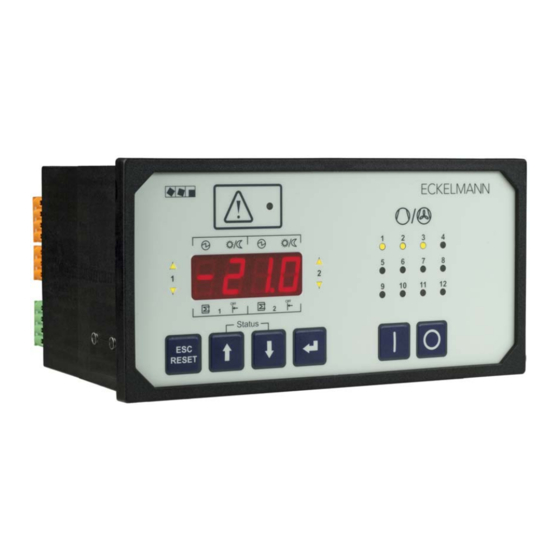
Page 89: Controls
Operation of VS 300 7.1.2 Controls (8) (10) (9) (11) (6) (7) Status RESET (12) (14) (16) (13) (15) (17) Description of controls and their function (see illustration). Key/Switch Function in basic display mode Function in parameter setting mode (see chapter 7.5) -
Page 90: First Start – Loading Default Values
7 Parameter List and Menu Structure). At first startup, the default settings for all parameters are loaded and all archives, messages/alarms and operating data (e.g. run times, starts, activity) are deleted! 7.3 Menu and operating structure of VS 300 Basic display mode Example:... -
Page 91: Parameter Setting – General
RESET 7.5 Basic display mode On powering up or after 5 minutes during which no entry is made, the VS 300 switches to basic display mode and displays the actual value for t (Control Loop 1 temperature). The control loop for which the value is shown in basic display mode is additionally indicated by flashing of the status LEDs for Control Loop 1 Pressure High / Neutral Zone / Low on the left of the four-digit display. -
Page 92: Selecting Parameter Lists
See section 7 Parameter List and Menu Structure for details of the VS 300 parameter list. This section contains detailed descriptions of the parameters available, their allowed range and the conditions under which they can be changed. -
Page 93: Changing The Access Level
(see section 7 Parameter List and Menu Structure). Parameter S100 is taken as an example to de scribe operation of the VS 300 and changing of setpoints in the parameter lists (S1 - S4). Setpoints can only be changed at the Setpoint Adjustment Enabled access level (see section 7.7 Changing the Access Level). -
Page 94: Setting The Current Date And Time (Parameter List S2)
Date and time only need to be set, and only can be set, in stand-alone operation! When the VS 300 is connected via CAN bus module to a master clock (CI 3000 or AL 300), the date and time will be supplied by this master and applied to the VS 300, meaning that they then cannot be changed. -
Page 95: Parameter Groups
Use the ↓ and ↑ keys to change the value within the allowable range. See section 7 Parameter List and Menu Structure for detailed information on the VS 300 parameter lists. This section describes the parameters avail able, their allowable range and the conditions under which they can be changed. -
Page 96: Setting Parameters For The Week Timer (Parameter List T)
7.11 Setting parameters for the week timer (Parameter List t) Parameter are set for the timers in Parameter List t. The VS 300 contains 7 timers for each of the two control loops. Select the timers with the corresponding parameter by pressing the ↵ key (see section 7 Parameter List and Menu Structure - Parameter List t - Timers). -
Page 97: Manual Control / Service Mode (Parameter List C)
Operation of VS 300 7.12 Manual control / Service mode (Parameter List C) Parameter List C takes you to service mode. In check (service) mode, all analog outputs and the digital relay/ control stages can be actuated manually. First, the two controllers are deactivated or all relay/control stages are unloaded. - Page 98 Operation of VS 300 E001..E246 ( 1) Message/alarm code: ( 2) Message/alarm status: 0: not active / 1: active ( 3) Receive time stamp: ( 4) Receive time stamp: Month ( 5) Receive time stamp: Year ( 6) Receive time stamp:...
-
Page 99: Operation System Centre / Store Computer / Operator Terminal
Operation of VS 300 7.14 Operation System Centre / Store Computer / Operator Terminal 7.15 Operation possibilities The controller provides menus and screens for the display and adjustment of values. However, no operation for this is provided on the controller itself. The actual operation of these menus is performed externally using the following possibilities: S Remote control via the terminal: The controller can be operated remotely (e.g. -
Page 100: Remote Control Via A Terminal
Operation of VS 300 7.16 Remote control via a terminal Further details for the operation of a system centre, store computer or operator terminal can be found in their operating manuals. For the remote control of a controller, it makes no difference whether this is done with a system centre (A), a store computer or with an operator terminal (B) as the user interfaces on the terminals are almost identical and the same functions are available. -
Page 101: Menus And Operating Screens
Operation of VS 300 7.16.1 Menus and operating screens If the system centre, store computer or operator terminal remain locked down, settings on the con troller are read-only. Changes and inputs are not possible. However, if any parametrisation is required, the lock-down for the input must be removed first, see chapter 7.16.3. - Page 102 Operation of VS 300 Menus A menu can contain up to ten menu items (0 .. 9; 0 for menu item 10). After the selection of a menu item using the cursor buttons (↑) and (↓) and by tapping the ENTER button (↵) or by tapping the buttons 0..9), other sub...
-
Page 103: Calling The Controller Menu Via Remote Control
Operation of VS 300 Entering text In fields that allow text entry, text can also be entered by the alphanumeric keypad. Repeatedly press the nu meric keys to generate letters. Press the ENTER key (↵) to confirm the entered value or text. -
Page 104: System Centre Ci 4X00
Operation of VS 300 7.16.2.1 System Centre CI 4x00 The terminal for remote control of the controller (Menu 2-2 or Menu 4-2) is called in the system centre as fol lows: Step 1: Tap "2 - System overview" or "4 - Configuration" in the main menu. -
Page 105: Deactivating The Input Lock-Down
Operation of VS 300 7.16.3 Deactivating the input lock-down Operation via system centre, store computer or operator terminal is only possible for controllers with CAN bus connection; the removal of the lock-down is then applicable for all components in the CAN bus system. The lock-down is automatically reactivated 15 minutes after the last button tap. -
Page 106: Activating Service Mode
Operation of VS 300 7.16.4 Activating service mode For repair and maintenance work, service personnel can deactivate the remote alarm function of the system centre and of the store computer for a limited period using the service mode. The activation of the service mode must only be carried out by service personnel. -
Page 107: Parameter List And Menu Structure Of Vs 300
The integral user interface or an external terminal (CI 3000 Store Computer and AL 300 Operator Terminal) can be used for configuring, parameter setting and operation of the VS 300 Pack Controller by means of menus and screens. The following sections describe the parameter list of the VS 300 and the menu structure of the external in detail. -
Page 108: Parameter List A: Actual Values System Data
Number of relay stages CL1 [Value S301] + Number of relays CL2 [Value S331] + number internal alarm relay <= Number of relay stages VS 300 (varying with expansion stage/number of relay stages can be 4/8/12) Doku-Version 2.05 - Firmware 2.10 - 15. September 2017... -
Page 109: Parameter List S1: Overview Of Main Setpoints - Day/Night Operation
Parameter List and Menu Structure of VS 300 Values of more than 4 digits (e.g. 21900 operating hours) are displayed with the help of the relay stage operating and status indicators (LED flashing) as follows: Value = Value of LED display [0 - 9999] + (Number of flashing operating and status indicator LED * 10000) -
Page 110: Parameter List S2: Setpoints Basic Parameters - Night Operation
Parameter List and Menu Structure of VS 300 8.1.5 Parameter List S2: Setpoints Basic Parameters - Night Operation Function/ Range Default Dim. Displayed / Condition Description S210 S250 Second setpoint t -50..45 °C Minimum of stage must be defined in CL: CL1: S301 >... -
Page 111: Parameter List S2: Setpoints Basic Parameters - Day/Night Operation
Parameter List and Menu Structure of VS 300 8.1.6 Parameter List S2: Setpoints Basic Parameters - Day/Night Operation Function/ Range Default Dim. Displayed / Condition Description (1): Minimum of one stage must be defined in CL1: S301 > 0 CL2: S331 > 0... - Page 112 Parameter List and Menu Structure of VS 300 Function/ Range Default Dim. Displayed / Condition Description (1): Minimum of one stage must be defined in CL1: S301 > 0 CL2: S331 > 0 (2): Only shown when CL configured as HP...
-
Page 113: Parameter List S2: Common Setpoints
---, 101..109 Date and time only need to be set, and only can be set, in stand-alone operation! When the VS 300 is connected via CAN bus module to a master clock (CI 3000 Store Computer or AL 300 Operator Termi... - Page 114 Parameter List and Menu Structure of VS 300 Function/ Range Default Dim. Displayed / Condition Description (1): Minimum of one stage must be defined in CL: CL1: S301 > 0 CL2: S331 > 0 S304.1.. S334.11. Enable/disable relay/ 0: Disabled S304.12...
-
Page 115: Parameter List S3: Common Setpoints System Configuration
Parameter List S3: To change values set access level to setpoint adjustment enabled (Parameter A060=1, see section 7.7 Changing the Access Level). * Maximum value, depends on VS 300 system / number of alarm ralais: 4/8/12! Doku-Version 2.05 - Firmware 2.10 - 15. September 2017... -
Page 116: Parameter List S3: Basic Settings System Configuration
Parameter List and Menu Structure of VS 300 8.1.10 Parameter List S3: Basic Settings System Configuration Function / Range Default Dim. Displayed / Parameter Description Condition S390 Select controller confi 0: CL1 = LT control guration CL2 = LT control... -
Page 117: Parameter List S4: Setpoints Alarm Priorities
Parameter List and Menu Structure of VS 300 Controller configuration must be made prior to making individual parameter settings, as first start is performed after changing configuration! In first start, default settings are loaded for all parameters and all archives (alarms and operating data, e.g. -
Page 118: Parameter List S5: Suction Pressure Shift / Additional Parameters
Parameter List and Menu Structure of VS 300 Parameter Alarm priorities for: Range Default Displayed / Condition S434 No UA300 available (with control by refri geration point activa ted) S435 No load level informa -: Not recorded tion received CL1 0: Only entered in report list (with to shift by refrige... -
Page 119: Parameter List T: Setpoints Timers
Parameter List and Menu Structure of VS 300 8.1.13 Parameter List t: Setpoints Timers Function/ Range Dimension Default Displayed / Condition Description t000 t020 Setpoint toggle 0: External internal/external 1: Internal t001 t021 Timer 1 Sd 0..10 0: Mon 6: Sun... -
Page 120: Parameter List C: Service / Check Mode - Defaults Relay Outputs
02 Number of relay stages CL1 [ValueS301] + Number of relays CL2 [Values S331] + number internal alarm relay <= Number of relays stages VS 300 (varying with expansion stage/number of relay stages can be 4/8/12) Parameter List C: To change values set access level to setpoint adjustment enabled (Parameter A060=1, see section 7.7 Changing the Access Level). -
Page 121: Parameter List F: Alarms - System And Process Fault Reports
Parameter List and Menu Structure of VS 300 8.1.16 Parameter List F: Alarms - System and Process Fault Reports The status LEDs of the relay/control stages indicate the currently displayed alarm detail (see illustration: day (15th) of receive time stamp is displayed):... - Page 122 Parameter List and Menu Structure of VS 300 ( 1) Message/alarm code: E001..E246 ( 2) Message/alarm status: 0: not active / 1: active ( 3) Receive time stamp: ( 4) Receive time stamp: Month ( 5) Receive time stamp: Year...
-
Page 123: Overview Of Alarm Types
Parameter List and Menu Structure of VS 300 8.2 Overview of alarm types The following alarms are recorded by the VS 300 and saved to report memory: S System fault reports S Process fault reports Parameter System fault reports E000... -
Page 124: Menu Structure Of Al 300 Operator Terminal And Ci 3000 Store Computer
External operation requires a CAN bus module to allow communication with the VS 300 (see section 1 Design). When operating the VS 300 by an external terminal, entries cannot be made with the keys on the VS 300 and the “... -
Page 125: Menu Structure
Parameter List and Menu Structure of VS 300 8.4 Menu structure Main Menu overview Depending on type, expansion stage and configuration of the system, alternative terms may be used in menus and screens. These terms are shown in italics in the menus and screens that follow. - Page 126 Parameter List and Menu Structure of VS 300 Level 1 Level 2 Level 3 Screen No. Screen Name Setpoints CL1 Control SETPOINTS Control type 3-2-1 CL1-CONT to-adjustment 3-2-2 to-adjust. Actuating times CL1 3-2-3 LOAD TIMES LP/HP control day CL1 3-2-4...
- Page 127 Parameter List and Menu Structure of VS 300 Level 1 Level 2 Level 3 Screen No. Screen Name Operating Data Daily operating data Starts night 6-3-6 History CL1 Activity 6-3-7 History CL1 Activity day 6-3-8 History CL1 Activity night 6-3-9...
-
Page 128: Menu 0 Main Menu
Parameter List and Menu Structure of VS 300 8.4.1 Menu 0 Main menu VS 300 POS: XXXXX Next: Menu 1 1 Summary Next: Menu 2 2 Actual Values Next: Menu 3 3 Setpoints Next: Menu 4 4 Clock Next: Menu 5... - Page 129 Number of relay/control stages CL1 [1..n] + Number of relays CL2 [n+1..m] + Number internal alarm relay <= Number of relay/control stages VS 300 (max. 4/8/12 depending on expansion stage and configuration), see section 4.1.1 System Configuration - Allocation of Relay/Control Stages...
-
Page 130: Menu 3 Setpoints
Number of relay/control stages CL1 [1..n] + Number of relays CL2 [n+1..m] + Number internal alarm relay <= Number of relay/control stages VS 300 (max. 4/8/12 depending on expansion stage and configuration), see section 4.1.1 System Configuration - Allocation of Relay/Control Stages... - Page 131 Parameter List and Menu Structure of VS 300 S Menu 3-1 System Configuration (CL1) Entry Default CONFIG POS: XXXXX Dim. Number of compressors/fans (base load 2/4/6 2/4/6 2/4/6 No. Comp./Cond CL1 stages) in CL1 With step control: 0 - max.
- Page 132 Parameter List and Menu Structure of VS 300 S Menu 3-1 System Configuration (CL2) Default Entry CONFIG POS: XXXXX Dim. Number of compressors/fans (base load 2/4/6 2/4/6 2/4/6 No. Comp./Cond CL2 stages) in CL2 With step control: 0 - max.
- Page 133 Parameter List and Menu Structure of VS 300 ↑, ↓, Booster operation: disable shutdown CL2, SperrRK2 m. RK1 when compressor running in CL2 (only (ON/OFF) shown in Superuser mode) → Controller configuration (NT/LT/HP) See Screen 3-1-i Config XXXX (only configuarble in terminal mode and...
- Page 134 Parameter List and Menu Structure of VS 300 S Screen 3-1-b Refrigerant Control Loop 1 Entry Default REFRIGT. POS: XXXXX Dim. √ R 22 √ R 502 √ R 134a √ √ √ √ √ R 404A √ R 402A √...
- Page 135 Parameter List and Menu Structure of VS 300 S Screen 3-1-c Sensor Control Loop 1 Input Default TRANSD.CL1 POS: XXXXX Dim. Set sensor parameter: Pressure at 4mA 0,0..2,0 px 4mA XXX b Set sensor parameter: Pressure at 20mA 8,0..60,0 10,0...
- Page 136 Parameter List and Menu Structure of VS 300 S Screen 3-1-i Controller configuration - only shown in Superuser mode! Default Entry Config POS: XXXXX Dim. √ LTLT Controller configuration must be made prior to making individual pa √ rameter setting, as first start is per...
- Page 137 Parameter List and Menu Structure of VS 300 S Screen 3-2-1-a Control type CL1 Default Entry CONTROL POS: XXXXX Dim. √ √ √ √ √ Select control type for CL1 Step controller √ Speed controller √ Combi controller S Menu 3-2-2 to adjustment control loop 1...
- Page 138 Parameter List and Menu Structure of VS 300 S Menu 3-2-4 LP/HP Control Day Control Loop 1 Entry Default LP/HP-COND D POS: XXXXX Dim. setpoint for CL1; -50 - 45 °C tx-Max. CL1 XXX°C with setpoint shift activated: max. t setpoint for setpoint shift CL1 min.
- Page 139 Parameter List and Menu Structure of VS 300 S Menu 3-3 Setpoints for CL2 Control SETPOINTS POS: XXXXX Next: Screen 3-3-1 1 Control type Next: Screen 3-3-2 2 to adjustment CL2 Next: Screen 3-3-3 3 Load times CL2 Next: Screen 3-3-4 4 LP/HP cont.
- Page 140 Parameter List and Menu Structure of VS 300 S Menu 3-3-2 to adjustment control loop 2 Entry Default to adjust. POS: XXXXX Dim. → → Select input quantity for to shift See Screen 3-3-2-a to-Schiebung Enter maximum load level for suction 70..100...
- Page 141 Parameter List and Menu Structure of VS 300 S Menu 3-3-4 LP/HP Control Day Control Loop 2 Entry Default HP-CONT D POS: XXXXX Dim. setpoint for CL2; -50 - 45 °C tx - Max. XXX °C when setpoint shift activated: max.
- Page 142 Parameter List and Menu Structure of VS 300 S Menu 3-4 Monitoring CL1/CL2 Entry Default Monitoring POS: XXXXX Dim. High Pressure CL1 alarm is generated if -30 - 55 °C tx-Hi Warn. CL1 XXX °C temperature in CL1 rises above this level...
- Page 143 Parameter List and Menu Structure of VS 300 No. of compressor stages Default No. of compressor stages at HP fault 1 - 2 3 - 5 6 - 7 8 - 10 11 - 12 S Menu 3-5 Inputs INPUTS...
- Page 144 Parameter List and Menu Structure of VS 300 S Screen 3-5-1-a Function Digital Input 1 Entry Default Function POS: XXXXX Dim. √ √ Initiate fast unload FastRet. √ Initiate load shedding LoadShed.. √ Initiate setpoint toggle SetpTog. √ √ √...
- Page 145 VS 300 POS: XXXXX ESC, ↵ Back up parameters: The VS 300 allows of saving a backup set of data Save Parameters? that will be loaded instead of the default settings in occurrence of an inter nal error (inconsistency in parameter memory).
-
Page 146: Menu 4 Clock
Parameter List and Menu Structure of VS 300 8.4.5 Menu 4 Clock Entry Default CLOCK POS: XXXXX Dim. → Show current date/time Screen 4-a Current time ↑, ↓ Setpoint toggle external or by internal Setp.toggle CL1 clock CL1 (EXT, INT) →... -
Page 147: Menu 5 Alarms
Number of relay/control stages CL1 [1..n] + Number of relays CL2 [n+1..m] + Number internal alarm relais <= Number of relay/control stages VS 300 (max. 4, 8, 12 depending on expansion stage and configuration); see section 4.1.1 System Configuration - Allocation of Relay/Control Stages... - Page 148 Number of relay/control stages CL1 [1..n] + Number of relays CL2 [n+1..m] + Number internal alarm relais <= Number of relay/control stages VS 300 (max. 4, 8, 12 depending on expansion stage and configuration); see section 4.1.1 System Configuration - Allocation of Relay/Control Stages...
- Page 149 Number of relay/control stages CL1 [1..n] + Number of relays CL2 [n+1..m] + Number internal alarm relais <= Number of relay/control stages VS 300 (max. 4, 8, 12 depending on expansion stage and configuration); see section 4.1.1 System Configuration - Allocation of Relay/Control Stages...
- Page 150 Number of relay/control stages CL1 [1..n] + Number of relays CL2 [n+1..m] + Number internal alarm relais <= Number of relay/control stages VS 300 (max. 4, 8, 12 depending on expansion stage and configuration); see section 4.1.1 System Configuration - Allocation of Relay/Control Stages...
- Page 151 Number of relay/control stages CL1 [1..n] + Number of relays CL2 [n+1..m] + Number internal alarm relais <= Number of relay/control stages VS 300 (max. 4, 8, 12 depending on expansion stage and configuration); see section 4.1.1 System Configuration - Allocation of Relay/Control Stages...
- Page 152 Number of relay/control stages CL1 [1..n] + Number of relays CL2 [n+1..m] + Number internal alarm relais <= Number of relay/control stages VS 300 (max. 4, 8, 12 depending on expansion stage and configuration); see section 4.1.1 System Configuration - Allocation of Relay/Control Stages...
- Page 153 Number of relay/control stages CL1 [1..n] + Number of relays CL2 [n+1..m] + Number internal alarm relais <= Number of relay/control stages VS 300 (max. 4, 8, 12 depending on expansion stage and configuration); see section 4.1.1 System Configuration - Allocation of Relay/Control Stages...
- Page 154 Number of relay/control stages CL1 [1..n] + Number of relays CL2 [n+1..m] + Number internal alarm relais <= Number of relay/control stages VS 300 (max. 4, 8, 12 depending on expansion stage and configuration); see section 4.1.1 System Configuration - Allocation of Relay/Control Stages...
- Page 155 Number of relay/control stages CL1 [1..n] + Number of relays CL2 [n+1..m] + Number internal alarm relais <= Number of relay/control stages VS 300 (max. 4, 8, 12 depending on expansion stage and configuration); see section 4.1.1 System Configuration - Allocation of Relay/Control Stages...
-
Page 156: Menu 7 Basic Settings
Number of relay/control stages CL1 [1..n] + Number of relays CL2 [n+1..m] + Number internal alarm relais <= Number of relay/control stages VS 300 (max. 4, 8, 12 depending on expansion stage and configuration); see section 4.1.1 System Configuration - Allocation of Relay/Control Stages... - Page 157 4/8/12 (ON/OFF) This screen is only displayed when the VS 300 is configured with an internal alarm relay (1 or 2)! see section 4.1.1 System Configuration - Allocation of Relay/Control Stages Doku-Version 2.05 - Firmware 2.10 - 15. September 2017...
- Page 158 Parameter List and Menu Structure of VS 300 Notice: Doku-Version 2.05 - Firmware 2.10 - 15. September 2017...
-
Page 159: Decommissioning And Disposal
The scope of our delivery is designated as a component exclusively for further processing. As a consequence of this fact, Eckelmann AG does not undertake any measures for the taking back or munici pal recycling of this product as it is not supplied directly to the free market. - Page 160 Decommissioning and disposal Notice: Doku-Version 2.05 - Firmware 2.10 - 15. September 2017...
-
Page 161: Alarms And Messages Of Vs 300
Messages/alarms are shown both as message/alarm codes on the four-digit seven-segment LED display of VS 300 integral user interface and in real language on the display of the external AL 300 Operator Terminal or CI 3000 Store Computer when connected. -
Page 162: Messages / Alarms In The Vs 300
Alarms and Messages of VS 300 10.3 Messages / alarms in the VS 300 Status RESET Message/alarm code shown on display - process fault report E212 in this example These message/alarm codes can be displayed in more detail by opening Parameter List F on the integral user interface. - Page 163 Alarms and Messages of VS 300 Status LED Message/alarm details displayed (see illustration on previous page) Message/alarm code: E001...E246 For details see section 8.3 Message/Alarm Types or section 7 Parameter List and Menu Structure - Parameter List F Message/alarm status:...
-
Page 164: Messages / Alarms Al 300 Operator Terminal Or Ci 3000 Store Computer
See section 7 Parameter List and Menu Structure for detailed information on the menu structure of the AL 300 Operator Terminal or CI 3000 Store Computer. 10.5 Message / alarm types The following messages/alarms are recorded by the VS 300 controller and saved to the report memory: S Process fault reports S System fault reports Different terms may be used in the menus and screens depending on type, scope and configuration of the sys... -
Page 165: System Fault Reports
10.6 System fault reports RAM error is a fatal error and causes the VS 300 Pack Controller to go into fault status, as correct running of the program is then no longer likely. The watchdog attempts to reset the controller and force a restart. The controller will not start if the RAM error is permanent. - Page 166 Alarms and Messages of VS 300 Notice: Doku-Version 2.05 - Firmware 2.10 - 15. September 2017...
-
Page 167: Specifications Of Vs 300
11 Specifications of VS 300 11.1 Electrical data Overvoltage category III / pollution degree 2: All device connections designed for use with 230 V AC supply voltage must be connected to the same phase conductor. 400 V AC between neighbouring connection terminals is not permitted! - Page 168 VS 300 Weight 4 Relay 970 g (without CAN bus) 8 Relay 1110 g (with CAN bus) 12 Relay 1220 g (with CAN bus) Enclosure IP20 CE conformity - 2014/35/EU (Low Voltage Directive); Official Journal of the EU L96, 29/03/2014, p. 357-374 - 2014/30/EU (EMC Directive);...
-
Page 169: Mechanical Data
11.2 Mechanical data 98,9 PE (M4x10) Status RESET 13,5 +0,8 (1) Control panel (2) Installation cutout (3) Air circulation clearance Doku-Version 2.05 - Firmware 2.10 - 15. September 2017... - Page 170 Notice: Doku-Version 2.05 - Firmware 2.10 - 15. September 2017...
-
Page 171: Order No.'s And Accessories Of Vs 300
Order No.'s and accessories of VS 300 12 Order No.'s and accessories of VS 300 12.1 VS 300 Compact pack controller Type Description Order number VS 300 - 4 relay Compact pack controller with 4 relay outputs EVS300A001 stand alone (without CAN bus) - Page 172 Order No.'s and accessories of VS 300 Notice: Doku-Version 2.05 - Firmware 2.10 - 15. September 2017...
Need help?
Do you have a question about the VS 300 and is the answer not in the manual?
Questions and answers