Table of Contents
Advertisement
Quick Links
Advertisement
Chapters
Table of Contents

Related Manuals for Doosan DX22


Summary of Contents for Doosan DX22
- Page 1 950106-106013EN Operation & Maintenance Manual GENERATOR ENGINE DX22...
- Page 2 WARNING: Breathing diesel engine exhaust exposes you to chemicals known to the State of California to cause cancer and birth defects or other reproductive harm. • Always start and operate the engine in a well-ventilated area. • If in an enclosed area, vent the exhaust to the outside. •...
- Page 3 The design of our product may be changed without prior notice and Hyundai Doosan Infracore shall not be held liable for the failure of this manual to contain all the design changes made to improve the product.
-
Page 5: Table Of Contents
Table of Contents 1. Introduction ..........................1 General Information ........................... 3 Danger, Warning, Caution, and Notes ....................... 4 Engine Care ............................... 7 2. Operation and Maintenance .....................9 Starting and Stopping the Engine ......................11 Engine Break-In ............................12 Running the Engine in Winter ........................13 Engine Inspections and Maintenance ...................... - Page 6 7. Lubrication System .........................95 Overview and Specifications ........................97 8. Fuel System ..........................99 General Information ..........................101 Fuel System Components ........................102 9. Intake/Exhaust System ......................123 General Information ..........................125 Turbocharger ............................125 10. Cylinder Block/Head ......................135 General Information ..........................137 Cylinder Block ............................
-
Page 7: Introduction
1. Introduction General Information ......................3 General Information ............................. 3 Danger, Warning, Caution, and Notes ..................4 General Information ............................. 4 General Precautions ............................ 5 Cautions for Starting the Engine ........................5 Cautions for Inspections and Maintenance....................5 General Information ............................. 6 Other Safety Instructions and Environmental Pollution................ -
Page 9: General Information
Using non-genuine imitation parts or recycled parts may cause critical damage and faults in engine performance. Hyundai Doosan Infracore shall not be held liable for any damage or faults resulting from the use of such parts. The maintenance methods stated in this Operation and Maintenance Manual are the most efficient and safest work procedures. -
Page 10: Danger, Warning, Caution, And Notes
In the event that the V-belt safety guard is not installed, do not approach DANGER the engine while it is running. Hyundai Doosan Infra- core is not responsible for accidents or injuries Make sure to comply with these instructions; failure to which occur without the V-belt safety guard installed. -
Page 11: General Precautions
'Danger.' 'Warning' and 'Caution' items. Spurting fluid may cause physical injuries. Please contact Hyundai Doosan Infracore if there is any uncertainty regarding the contents of this manual or if you 3. When draining engine oil, make sure to prepare a container have any questions. -
Page 12: General Information
6. When replacing parts, make sure to replace them with public institutions. genuine Hyundai Doosan Infracore parts. Using imitation 10. Spilling or allowing engine oil or fuel to leak into the or recycled parts may cause severe faults with an impact ground may cause severe environmental pollution of on engine performance. -
Page 13: Engine Care
Hyundai Doosan Infracore shall not be held liable. For details nants. regarding the intended uses and purposes of the engine, please contact our sales department. -
Page 14: Preventing Pollution
Do not spray high-pressure water directly on the engine. EN590, apart from HVO having a somewhat lower density. It may damage engine parts, electronic parts, and wiring. Hyundai Doosan Infracore approves the use of up to 100% Preventing Pollution HVO for engines in accordance with the EU standard EN15940. -
Page 15: Operation And Maintenance
2. Operation and Maintenance Starting and Stopping the Engine ..................11 Preparing to Start............................11 When Starting the Engine .......................... 11 Immediately after Starting the Engine......................11 During Operation............................11 When Stopping ............................11 Engine Break-In ........................12 General Information ........................... 12 Breaking in New Engines........................... -
Page 17: Starting And Stopping The Engine
Use only fuel, oil, coolant, etc. recommended by Hyundai Hence, in the event of abnormal noise or vibrations, lower Doosan Infracore. Otherwise, severe engine faults may the engine rpm slowly; then, stop the engine and deter- occur. -
Page 18: Engine Break-In
General Information In order to provide only engines of the highest quality, Hyundai CAUTION Doosan Infracore ensures that engines undergo a final acceptance test before releasing them from the factory. The oil pressure may increase and decrease along with However, since the engines are not run for an extended period the engine speed (rpm). -
Page 19: Running The Engine In Winter
When replacing engine oil, please use genuine oil recommended by Hyundai Doosan Infracore. Running the Primary Fuel Filter (Oil-Water Separator) Heater... -
Page 20: Engine Inspections And Maintenance
2. Operation and Maintenance Engine Inspections and Maintenance Note) If the heater switch on the generator control panel is left on while the engine is turned off, the current consumption resulting from unnecessary operation of Checking Engine Parts after Prolonged the fuel heater mounted on the primary fuel filter may Operation cause the battery to discharge. -
Page 21: Intake System
2. Operation and Maintenance Intake System 4. Normal state of common rail and high-pressure pump wiring fasteners Be careful when handling the air filter of the intake system. In If the fasteners for the common rail pressure sensor the case of wet-type air filters, filtration performance is (RPS) and high-pressure pump fuel metering unit (FMU) degraded when the oil level drops below the specified amount, whereas oil may enter and contaminate the case if... - Page 22 2. Operation and Maintenance...
-
Page 23: Performance And Specifications
3. Performance and Specifications Engine Specifications and Performance ................19 Engine Specifications..........................19 Engine Power............................. 21 Outside Drawing of the Engine ...................22 Structural Diagram ............................. 22 Left/Right Sectional View ........................... 23 Top View ..............................24 Engine Serial Number ......................25 Engine Code and Production Number ....................... 25 Numbers Stamped on the Engine...................... -
Page 25: Engine Specifications And Performance
3. Performance and Specifications Engine Specifications and Performance Engine Specifications Specifications Item Remarks DX22 Non Tier DX22 Tier 2 DX22 CN3 General Information Engine type Four-stroke, V-type, water-cooled, turbocharged and air-cooled Combustion chamber type Direct injection Cylinder liner type Wet liner... - Page 26 3. Performance and Specifications Specifications Item Remarks DX22 Non Tier DX22 Tier 2 DX22 CN3 Front/rear/left/ Allowable tilt angle of oil pan 10° / 10° / 15° / 15° right Oil pump type External spur gear type Oil cooler type...
-
Page 27: Engine Power
3. Performance and Specifications Engine Power Gross Engine Output Net Engine Output Ratings (kWm/PS) Standby Prime Standby Prime 875/1,190 790/1,074 560/761 854/1,161 769/1,045 539/733 1,500 rpm (50 Hz) 875/1,190 802/1,090 561/763 854/1,161 781/1,062 540/734 1,800 rpm 995/1,353 900/1,224 641/872 958/1,303 863/1,174 604/822 (60Hz) -
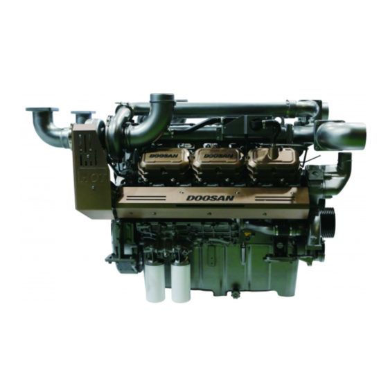
Page 28: Outside Drawing Of The Engine
3. Performance and Specifications Outside Drawing of the Engine Note) The images shown represent the standard model; they do not include all models. Structural Diagram EDX22190001 1. Lifting hook 5. Mounting bracket 9. Breather 2. Turbocharger 6. Coolant pump 10. Oil filler cap 3. -
Page 29: Left/Right Sectional View
3. Performance and Specifications Left/Right Sectional View EDX22190002 1. Breather 5. Starter Motor 9. Oil pan 2. Intake manifold 6. Lifting hook 10. Drain plug 3. Turbocharger 7. Heat shield & exhaust manifold 4. Oil filler cap 8. Coolant pipe... -
Page 30: Top View
3. Performance and Specifications Top View EDX22190003 1. Cylinder head cover 3. Turbocharger 5. Injector pump 2. Air pipe 4. Timing gear case... -
Page 31: Engine Serial Number
3. Performance and Specifications Engine Serial Number Engine Code and Production Number • Type 5 The engine code and production number are required for warranty claims and part orders. A. Model name (4 - 7 digits) B. Year (1 digit) Numbers Stamped on the Engine C. - Page 32 3. Performance and Specifications...
-
Page 33: Regular Inspections
4. Regular Inspections General Information ......................29 General Information ........................... 29 Daily Inspections............................29 Maintenance Schedule .......................30 General Conditions ............................ 30 Cautions for Using Biodiesel ....................31 Allowable Fuel Under Warranty ......................... 31 Cautions for Using Biodiesel in Different Types of Generators..............31 Cooling System ........................32 General Information ........................... - Page 34 Intake/Exhaust System .......................42 General Information ........................... 42 Cleaning the Air Filter ..........................42 Cleaning the Air Cleaner Element......................43 Replacing the Air Cleaner Element......................43 Cylinder Block/Head ......................44 Adjusting the Valve Clearance........................44 Adjusting Sequence of Valve Clearance....................45 Electrical System ............................46 Battery................................
-
Page 35: General Information
Hyundai Doosan Infracore, the engine can be maintained in • Note that batteries, cables, and electrical wiring have its optimal state for long periods of time and unanticipated current running through them. -
Page 36: Maintenance Schedule
4. Regular Inspections Maintenance Schedule General Conditions Periodic inspections and replacements are absolutely necessary to ensure the optimum state of the engine during its service life and to prevent any unexpected engine failure. The maintenance schedule may differ depending on the operating conditions of the engine. -
Page 37: Cautions For Using Biodiesel
4. Japan: JIS K2204:2007 (lubricity ≤ 520μm, FAME max. recommend using fuel without any biodiesel added. Hyundai Doosan Infracore is not liable for any problems 5. China: GB252:2015 and GB19147:2013 in ESP generator engines resulting from the use of more 6. -
Page 38: Cooling System
3. The coolant level should lie between the upper and lower By maintaining the mixture ratio of coolant recom- limits indicated on the auxiliary tank. mended by Hyundai Doosan Infracore, engine corrosion 4. Add coolant if necessary. can be prevented effectively and the engine can be 5. -
Page 39: Measuring The Coolant Concentration
4. Regular Inspections Measuring the Coolant Concentration 2) Compare the color of part (B) of the test strip with the color in the MOLYBDATE (Middle pad) section of the • Special tool standard color table. Figure Part no. / name 3) Compare the color of part (C) of the test strip with the color in the NITRITE section of the standard color table. -
Page 40: Add Coolant
• Do not use a mixture of coolants with different concentrations. • Do not add an anti-rust agent which is not recom- mended by Hyundai Doosan Infracore. • A low coolant concentration may cause corrosion or freezing, whereas a high concentration may degrade cooling performance. -
Page 41: Cleaning The Cooling Circuit
4. The DX22 has a wet-type cylinder liner, so coolant must be managed even more carefully. Cleaning the Cooling Circuit 5. You can check the density of antifreeze and anticorrosive using a coolant test kit. -
Page 42: Lubrication System
4. Regular Inspections Lubrication System General Information Engine oil serves to enhance engine performance and prolong engine life by lubricating, cooling, sealing, preventing corrosion and cleaning the inside of the engine. Running the generator continuously without sufficient engine oil may cause moving parts in the engine to seize up, leading to engine failure. -
Page 43: Engine Oil Specifications
Temperature SAE 0W-40 SAE 5W-40 SAE 10W-40 SAE 15W-40 EDL06200023 The following engine oil specifications are recommended: Engine Model SAE Classification Oil Grade DX22 SAE 10W40 API CI 4 or higher Note) Use genuine oil recommended by Hyundai Doosan Infracore. -
Page 44: Engine Oil Capacity
5. Wipe off the indicator line on the oil level gauge with a clean cloth. 1. Remove the oil filler cap on the top of the engine. 2. Add genuine oil recommended by Hyundai Doosan Infra- CAUTION core. 1) Add the oil a small amount at a time. -
Page 45: Adding Engine Oil
1. Drain the engine oil. CAUTION • When replacing the oil filter cartridge, make sure to use a new genuine Hyundai Doosan Infracore cartridge. • The new oil filter must not contain any oil when it is installed. Do not fill the new oil filter with oil from the old oil filter. -
Page 46: Fuel System
4. Regular Inspections Fuel System General Information CAUTION Fuel quality is crucial for engine performance, engine life, and satisfying emissions standards. This engine is • Failing to check the fuel filter periodically and drain manufactured for use with standard fuel as specified by the water in the fuel filter causes moisture to enter international petroleum-related laws and the Clean Air the engine fuel system, leading to severe faults in the... -
Page 47: Engine Low-Pressure Fuel Lines
4. Regular Inspections Engine Low-Pressure Fuel Lines All low-pressure fuel lines are made of metal and have couplings which are shaped to fit the lines in order to maintain an airtight seal. When reused after repeated removal and reinstallation, the lines lose their airtightness and may cause fuel leaks, so make sure to replace the lines with new ones when they are removed. -
Page 48: Intake/Exhaust System
4. Regular Inspections Intake/Exhaust System General Information Cleaning the Air Filter The air filter serves to supply the engine with clean air by 1. Clean the air filter. filtering out dust and foreign matter contained in atmospheric 1) Empty the dust canister periodically. air. -
Page 49: Cleaning The Air Cleaner Element
4. Regular Inspections Cleaning the Air Cleaner Element Replacing the Air Cleaner Element Clean the air filter element using whichever of the following 1. Replace the air cleaner element. three methods is most suited to the work environment. 1. Use compressed air to clean the air filter element. EK00025A 1) Unscrew the hex nut and remove the dirty element. -
Page 50: Cylinder Block/Head
4. Regular Inspections Cylinder Block/Head Adjusting the Valve Clearance • Turn the crankshaft to set the piston of cylinder no. 1 at TDC of the compression stroke; then, adjust the valve clearance. • Unscrew the rocker arm mounting nut and fit the feeler gauge between the rocker arm and valve. Adjust the clearance of each cylinder with the adjustment screw;... -
Page 51: Adjusting Sequence Of Valve Clearance
4. Regular Inspections Adjusting Sequence of Valve Clearance Method 1 • Turn the crankshaft to set the piston of cylinder no. 1 at TDC of the compression stroke. Note) Cylinder no. 1 is where the coolant pump is installed. Note) In a 12-cylinder engine, when cylinder no. 1 is at TDC of the compression stroke, valve overlap occurs in cylinder no. -
Page 52: Electrical System
4. Regular Inspections Electrical System Battery 2. Check the electrolyte level and add distilled water as necessary. 1. Check the battery for electrolyte leakage due to cracks. If 3. Measure the specific gravity of the electrolyte. If the it is cracked, replace it with a new one. measurement is below the specified range (1.12 ~ 1.28), add more. -
Page 53: Other/Driving System
4. Regular Inspections Other/Driving System Belt tension 3. Measuring Tension Belt tension is maintained by an auto tensioner, so there is no need to adjust it. The belt must be replaced when the pointer indicates that a replacement interval is approaching. 1. - Page 54 4. Regular Inspections EDX22190046 4. The belt tension is as follows: Tension on the tester During service Installation after pro- Drive belt Type (10 minutes longed opera- width after tion operation) (replacement interval) 358 ~ 444 N 27.62 mm 8PK Micro V (80.48 ~ 220 N / 49.46 lbf (1.0874 in.)
-
Page 55: General Engine Information
5. General Engine Information Method of Indicating Units ....................51 Unit Conversion Methods........................... 51 Tightening Torque .......................52 Tightening Torque of Main Parts........................ 52 Tightening Torque of General Bolts ......................53 Tightening Torque of Plug Screws......................54 Tightening Torque of Hollow Screws (Four Holes) ..................54 Engine Disassembly ......................55 Order of Engine Disassembly ........................ -
Page 57: Method Of Indicating Units
5. General Engine Information Method of Indicating Units Unit Conversion Methods Item Number SI Unit US Unit This is a method for converting between SI and US units. 1.3596 Power 1. Multiply the SI unit by the numbers in the table below to 0.98635 obtain the US unit. -
Page 58: Tightening Torque
5. General Engine Information Tightening Torque Tightening Torque of Main Parts Name Main Parts Strength Tightening Torque (Dia. × pitch) Cylinder block bearing cap - Main bolt M18 × 2.0 12.9T 30 kgf·m (216.99 lbf·ft) + 90° (0 ~ 10°) - Side bolt M12 ×... -
Page 59: Tightening Torque Of General Bolts
5. General Engine Information Tightening Torque of General Bolts Refer to the following tightening torques for bolts whose tightening torque is not included in the list of the main parts. 1. Tightening torque of general bolts Strength class 10.9 12.9 Name (4A) (4D) -
Page 60: Tightening Torque Of Plug Screws
Tightening Torque of Plug Screws 10.0 10.0 12.0 12.0 15.0 Tightening Torque of Hollow Screws (Four Holes) Type of material SM25C 13.0 18.0 30.0 11.0 16.0 20.0 35.0 SUM22L STS304 11.0 16.0 20.0 35.0 a. Installed in Hyundai Doosan Infracore engines... -
Page 61: Engine Disassembly
5. General Engine Information Engine Disassembly Order of Engine Disassembly CAUTION • Before disassembly, prepare a shelf for parts to store various tools and disassembled parts. • When performing disassembly, make sure to use clean, bare hands and keep the workspace and its surroundings clean. - Page 62 5. General Engine Information 2) Unscrew the intercooler mounting bolts and remove the 1) Unscrew the cooling fan mounting bolts and remove the intercooler. cooling fan. 3. Oil level gauge 6. V-belt EDX22190042 EDX22190046 1) Remove the oil level gauge from the oil pan guide tube. 1) Rotate the auto tensioner clockwise and remove the belt.
- Page 63 5. General Engine Information 8. Air pipe EDX22190068 EDX22190066 2) Unscrew the hollow screws on the turbocharger lubri- 1) Loosen and remove connecting clamps (A) on the outlet cating oil supply and disconnect the oil pipes. of the intake manifold compressor. 3) Unscrew the bolts on the turbocharger lubricating oil 2) Be careful not to allow foreign matter to enter the turbo- drain and disconnect the oil pipes.
- Page 64 5. General Engine Information 10. Oil Filter 1) Unscrew the crankshaft pulley mounting bolts and remove both the crankshaft pulley and the vibration damper. 12. Coolant pump and thermostat EDX22190040 1) Use an oil filter wrench to remove the oil filter cartridge. 2) Do not reuse the cartridge.
- Page 65 5. General Engine Information 14. Fuel filter Inlet Inlet Inlet Outlet Outlet Outlet EDX22190076 EDX22190078 3) Disconnect the high-pressure pipes between common 1) Unscrew hollow screws (A) on the fuel filter and discon- rail (B), high-pressure fuel connectors (C) and fuel pumps nect the fuel pipes.
- Page 66 5. General Engine Information 17. Intake manifold 19. Oil cooler EDX22190079 EDX22190083 1) Loosen the hose clamps connected to the oil-water 1) Remove the coolant drain plug and drain the coolant. separator. 2) Unscrew the oil cooler cover mounting bolts and remove 2) Unscrew the oil-water separator bracket mounting bolts the oil cooler.
- Page 67 5. General Engine Information 1) Loosen the high-pressure fuel pump mounting bolts and 23. Injectors remove both high-pressure pumps from the timing gear case. 21. Cylinder head cover EDX22190088 1) Unscrew the mounting nuts on the high-pressure fuel connectors and remove the high-pressure fuel connectors. EDX22190086 2) Do not reuse high-pressure fuel connectors.
- Page 68 5. General Engine Information 1) Unscrew the cylinder head mounting bolts in the reverse 27. Pistons order of assembly and remove the cylinder head. 2) Remove and discard the cylinder head gasket. 3) Remove the residue on the contact surface between the cylinder head and cylinder block.
- Page 69 5. General Engine Information 29. Flywheel 31. Crankshaft EDX22190094 EDX22190096 1) Unscrew the flywheel mounting bolts in the reverse order 1) Remove the bolts from the bearing caps. of assembly and remove the flywheel. 2) Remove the main bearing cap mounting bolts in the 2) Remove the flywheel ring gear.
- Page 70 5. General Engine Information 33. Oil injection nozzle EDX22190097 1) Unscrew the oil injection nozzle mounting bolts and remove the oil injection nozzles. 34. Cylinder liner EDX22190108 1) Use a special tool to pull the cylinder liner out of the cylinder block.
-
Page 71: Engine Assembly
5. General Engine Information Engine Assembly Order of Engine Assembly 4) After completely assembling the cylinder liner, perform a hydrostatic test (4 kg/cm ) to check for leaks. CAUTION 2. Oil injection nozzle • Clean all parts thoroughly and blow compressed air into the various oil and coolant passages to clean them out completely. - Page 72 5. General Engine Information EDX22190110 EFM2062I 2) Assemble the main bearings on the cylinder block and 5) Assemble the bearing cap bolts in the correct tightening sequence at the specified tightening torque (30 kgf·m / apply engine oil to the bearings. When doing so, 216.99 lbf·ft) using the rotating angle method (90°+10°).
- Page 73 5. General Engine Information 5. Camshaft 5) Temporarily install two flywheel housing assembly guide bolts on the cylinder block. 6) Fit the flywheel housing holes onto the guide bolts and temporarily tighten the mounting bolts 2 ~ 3 threads; then, tighten them to the specified torque in the correct tightening sequence (zigzag pattern).
- Page 74 5. General Engine Information 3) Use an assembly jig to press fit the wear ring into the back of the flywheel so that the flywheel is aligned with the edge of the wear ring. (Apply Loctite #262 to the mounting surface) Flywheel housing Allowable...
- Page 75 5. General Engine Information 9. Oil seal holder (front) 10. Pistons EDX22190093 EDX22190120 1) After aligning the oil seal properly with the oil seal holder 1) Align the piston assemblies in order of their respective holes, use an insertion jig to install it. cylinders and insert the bearings into the connecting rods (Be careful not to damage the oil seal.) and bearing caps.
- Page 76 5. General Engine Information Assemble in the opposite "Y" or "TOP" direction of the snap ring EAMD090I EDX22190121 4) Make sure not to install the piston rings upside down. The < Connecting rod bolt tightening sequence > "Y" or "TOP" mark on top of the ring connection should •...
- Page 77 5. General Engine Information 12. Vibration damper EFM2070I EDX22190072 8) Move the connecting rod bearing caps by hand to check 1) Assemble the crankshaft pulley and vibration damper whether they move smoothly from side to side. after first tightening them with mounting bolts. 9) Rotate the crankshaft in the same way as described 2) Fit the crankshaft pulley assembly onto the crankshaft above when mounting it on each cylinder.
- Page 78 5. General Engine Information 13. Oil pan 15. Cylinder Head EDX22190090 EDX22190089 1) Use a scraper to completely remove the gasket 1) Blow into the cylinder head bolt holes with compressed protruding from the joint between the front oil seal holder air to completely remove all foreign matter.
- Page 79 5. General Engine Information 16. Injectors 173 mm EF8OM072 EDX22190088 6) Tighten the cylinder head bolts to the specified torque in several stages. Before assembling the bolts, make sure CAUTION to adjust the parallelism between the cylinder head with • When installing a new injection pipe after discon- a long steel ruler.
- Page 80 5. General Engine Information Install the high-pressure fuel Injector connector and temporarily tighten the mounting nut. High-pressure fuel connector Apply engine oil to the O-ring (take care not to allow oil to enter Where to apply engine oil the high-pressure - O-ring fuel connector) - Contact surface of...
- Page 81 5. General Engine Information 18. Flywheel housing cover Tighten the high-pressure fuel connector mounting nut to the final specified torque. Final step: Tightening the high-pressure fuel connector mounting nut EDX22190136 EDX22190124 6) Finish tightening injector mounting bracket mounting bolt 1) Apply a liquid gasket to the T-joint between the cylinder ④...
- Page 82 5. General Engine Information 19. Fuel injection pump EDX22190127 EDX22190085 4) Tighten the oil cooler and cover with mounting bolts. 1) After greasing the O-ring on the high-pressure fuel pump, 5) Install washers and apply Loctite to 2 cover mounting align the drive gear spline teeth on the timing gear case bolts (A);...
- Page 83 5. General Engine Information • Coolant pump and coolant pipe Torque 2.2 kgf·m (15.91 lbf·ft) 2) Tighten and assemble the coolant pump with mounting bolts in a zigzag pattern. 3) Fit the thermostat onto the coolant pump. 4) Fit an O-ring onto the thermostat and tighten the coolant pipe with mounting bolts to assemble it.
- Page 84 5. General Engine Information 4) Insert oil breather hose (A) and tighten it with a clamp to < Tightening sequence of fuel pipes between assemble it. low-pressure/high-pressure pump and junction block > a) Assemble injector fuel return pipe no. 1. Middle cover (C) and head cover (B) 2.2 kgf·m mounting bolt torque...
- Page 85 5. General Engine Information b) Assemble the junction block. c) Assemble the fuel return junction block. EDX22190224 EDX22190226 • The junction block is fastened to the junction block • The fuel return junction block is assembled on the side of bracket on top of the engine block and tightened with four the main junction block and tightened with two M8 bolts.
- Page 86 5. General Engine Information d) Assemble injector fuel return pipe no. 2. e) Assemble the fuel return junction block pipe and the fuel return pipe on the high-pressure fuel pump. EDX22190227 EDX22190231 • Injector fuel return pipe no. 2 is assembled with the fuel •...
- Page 87 5. General Engine Information EDX22190229 EDX22190232 High-pressure fuel pump fuel delivery pipe no. 1 Engine fuel return pipe High-pressure fuel pump fuel delivery pipe no. 2 Common rail fuel return pipe Hollow screw Hollow screw no. 2 g) Assemble fuel drain pipes no. 1 and no. 2 of the low-pres- Hollow screw no.
- Page 88 5. General Engine Information EDX22190235 EDX22190237 Low-pressure fuel pump fuel drain pipe no. 1 Low-pressure fuel pump fuel delivery pipe no. 1 Low-pressure fuel pump fuel drain pipe no. 2 Low-pressure fuel pump fuel delivery Hollow screw pipe no. 2 h) Assemble fuel delivery pipes no.
- Page 89 5. General Engine Information 29. Intake stake and air pipe 1 1 1 4 4 4 EDX22190132 EDX22190134 3) Apply gasket (B) to exhaust elbow (A) connected to the exhaust manifold and tighten the connecting nuts to assemble it. 4) Assemble both sides as described above. Manifold mounting 8 kgf·m bolts (A)
- Page 90 5. General Engine Information 1) Secure the bracket on the cylinder block and assemble 1.2 kgf·m the fuel filter. Clamp torque (A) (8.6796 lbf·ft) 2) When replacing the fuel filter with a new one, make sure Intercooler pipe 6.2 kgf·m to fill the cartridge inside with fuel before installing it.
- Page 91 5. General Engine Information 34. Cooling fan and fan drive EDX22190129 1) Install fan drive bracket (A) on the cylinder block and assemble the fan. 2) Assemble cooling fan (B) and fan flange (C) with mounting bolts; then, tighten them to the specified torque. 35.
- Page 92 5. General Engine Information...
-
Page 93: Cooling System
6. Cooling System Overview and Specifications ....................89 Overview ..............................89 Specifications............................. 90 Thermostat ..........................91 General Information ........................... 91 Inspection..............................91 Cautions for Replacing and Handling the Thermostat ................91 Causes of Faults and Troubleshooting ................92 Air Heater (Optional) ......................93 Operating Conditions ..........................93 Circuit Diagram ............................ -
Page 95: Overview And Specifications
6. Cooling System Overview and Specifications Overview Then, this coolant is conveyed to the thermostat through the coolant pipe. If the coolant temperature is lower than the This engine is water-cooled. After coolant absorbs valve opening temperature of the thermostat, it is returned to combustion heat from the combustion chamber and heat the coolant pump. -
Page 96: Specifications
6. Cooling System Specifications Item Specifications Type Centrifugal Supply Approx. 840 liter/min. (221.9 gal./min.) Coolant pump Pump speed 3,500 rpm Pump back pressure 1.8 kg/cm (25.6 psi) Thermostat Operating temperature 71 ~ 85 °C (160 ~ 185 °F) Fan diameter - number of blades Ø1,150 mm (45.28 in.) - 8 Cooling fan and belt Belt tension... -
Page 97: Thermostat
6. Cooling System Thermostat General Information Inspection The thermostat is used to maintain a constant coolant 1. Check the wax pellet and spring for damage. temperature and prevent heat loss in order to enhance the 2. Submerge the thermostat in water and heat the water engine's thermal efficiency. -
Page 98: Causes Of Faults And Troubleshooting
6. Cooling System Causes of Faults and Troubleshooting Symptom Possible Cause Troubleshooting Insufficient coolant Add coolant Loose radiator cap spring Replace the cap Loose or broken fan belt Adjust or replace the fan belt Fan belt contaminated with oil Replace the fan belt Malfunctioning thermostat Replace the thermostat Faulty coolant pump... -
Page 99: Air Heater (Optional)
6. Cooling System Air Heater (Optional) Operating Conditions -30 -20 Temperature (°C) Temperature (°C) EDX22190243 Circuit Diagram BATTERY(BATT) Terminal : M6 X 1.0 P PP Terminal : M6 X 1.0 P BATT C(Red) D(Black) BATT D(AVSS0.85 Black) C(AVSS0.85 Red) EDX22190241... - Page 100 6. Cooling System...
-
Page 101: Lubrication System
7. Lubrication System Overview and Specifications ....................97 General Information ........................... 97 Specifications............................. 97 Lubrication Circuit Diagram........................97 Oil Filter..............................98 Causes of Faults and Troubleshooting ...................... 98... -
Page 103: Overview And Specifications
7. Lubrication System Overview and Specifications General Information As engine oil is sucked and delivered from the oil pan by means of the gear-driven oil pump, all of it passes through the oil cooler and oil filter to be filtered; then, this filtered oil flows through the main oil gallery in the cylinder block to lubricate each engine bearing and the turbocharger in order to maintain normal engine performance. - Page 104 7. Lubrication System Oil Filter The oil filter installed in the engine is a cartridge-type filter. Make sure to replace it with a new one at the designated interval. EDX22190040 Causes of Faults and Troubleshooting Symptom Possible Cause Troubleshooting Poor oil quality Use the specified oil Leaky oil seal ring and packing Replace...
-
Page 105: Fuel System
8. Fuel System General Information ......................101 General Information ..........................101 Fuel System Components ....................102 Caution..............................102 Fuel Tank ..............................102 Fuel Lines Connected to the Engine......................103 Three-Way Valve ............................. 104 Hand Priming Pump and Connecting Adapter ..................104 Primary Fuel Filter, Connecting Adapter, Fuel Heater, Service Tool ............106 Engine Fuel Inlet/Outlet Ports ........................ -
Page 107: General Information
8. Fuel System General Information General Information This engine is equipped with a high-pressure common rail fuel injection system and consists of the components shown in the "fuel system schematic diagram" below. The system is designed to function optimally according to the engine performance. After leaving the fuel tank and passing through the primary fuel filter (oil-water separator), fuel is filtered of all water and large particles of foreign matter;... -
Page 108: Fuel System Components
8. Fuel System Fuel System Components Fuel Tank The fuel tank must be able to store fuel cleanly and safely Caution and must be structured to satisfy the following requirements • The common rail fuel injection system operates at high so as not to affect the components of the engine injection pressures (1800 bar). -
Page 109: Fuel Lines Connected To The Engine
8. Fuel System Fuel Lines Connected to the Engine Piping Layout Material While the engine is running EDX22190174 EDX22190172 Since the fuel lines connecting the engine and the fuel tank must be flexible enough to withstand vibrations while the engine is running, it is recommended to use hoses. The DP222C engine includes three two-meter fuel hoses (420103-00602) packaged separately and provided along While priming... -
Page 110: Three-Way Valve
8. Fuel System Three-Way Valve Installation Materials and Specifications EDX22190178 1. Remove the plug for preventing foreign matter from entering the hand priming pump and tighten the EDX22190176 connecting adapters provided to the specified torque. Zinc (Zn), copper (Cu), lead (Pb), sodium (Na) and calcium Torque 5 ±0.5 kgf·m (36.1651 ±3.6165 lbf·ft) (Ca) cause chemical reactions with water in fuel and... - Page 111 8. Fuel System 2. Pump the handle up and down by hand to prime the pump. EDX22190202 3. After priming is complete, press the handle into the compressed position by hand; then, wind it in the clock- wise direction to lock it. EDX22190203...
-
Page 112: Primary Fuel Filter, Connecting Adapter, Fuel Heater, Service Tool
8. Fuel System Primary Fuel Filter, Connecting Adapter, Fuel Heater, Service Tool Components A primary fuel filter, two piping connecting adapters, fuel heaters, and a service tool are provided as separate accessories along with the engine. Service tool Primary fuel filter assembly SAE J516 37 CONE 1 1/16-12 UNF Connecting adapter... - Page 113 8. Fuel System Installation Bleeder cap Tighten by hand until a single click is heard Min. 88.9 Min. 88.9 Min. 88.9 When removing the cover to When removing the cover to When removing the cover to Filter cover replace the filter replace the filter replace the filter Minimum required space...
- Page 114 8. Fuel System 1. Mounting the primary fuel filter and connecting the fuel lines Primary fuel filter assembly Fuel hose SW32 Connecting adapter SW27 Plug to prevent foreign Connecting adapter matter from entering SW27 Fuel hose SW32 Fuel inlet port SW29 Fuel outlet port Plug to prevent foreign...
- Page 115 8. Fuel System 2. Connecting the fuel heater Fuel heater port #2 Fuel heater port #1 50Hz, used in temperate regions 50Hz, used in temperate regions 60Hz, not for use in temperate regions 60Hz, used in temperate regions Do not use in tropical regions Do not use in tropical regions EDX22190184 The number of fuel heaters is defined by the frequency...
- Page 116 8. Fuel System Fuse Connection Key Controlled Thermo-Switch Switch Battery Heater Fuse Relay Relay Connection 30/51 Key Controlled Switch EDX22190144 • Fuel heater wiring circuit layout (for one heater) Item Heater Generator set Refer to circuit diagram APTIV 12103584 APTIV 12010973 •...
- Page 117 8. Fuel System 3. Connecting the water in fuel sensor switch WIF Light (LED) (Water In Fuel) Sensor Green Water detection switch Harness EDX22190189 The water in fuel sensor switch is used to notify the oper- Water in fuel sensor ator that drainage is necessary when the water collected Item Generator set...
- Page 118 8. Fuel System Operation 1. Fuel heater operation at low temperatures 1) To ensure smooth start-up in winter and at low tempera- tures, run and preheat the primary fuel filter heater five Open minutes before starting the engine to remove the paraffin in the fuel accumulated in the fuel filter.
- Page 119 8. Fuel System Primary fuel filter O-ring seal Fuel tank Three-way valve Fuel delivery O-ring seal O-ring seal Hand priming pump EDX22190196 EDX22190198 4) Remove the old cartridge and replace it with a new one; 6) Turn the manual valve on the fuel line supplying fuel from then, temporarily assemble the cover, nuts and cap in the the fuel tank to the fuel delivery position.
- Page 120 8. Fuel System When the fuel level in the filter reaches the cartridge marking above the cover mounting nuts, tighten the bleeder cap by hand until a single click is head; then, Primary fuel filter operate the three-way valve to cause fuel to flow into the primary filter and finish replacing the cartridge.
-
Page 121: Engine Fuel Inlet/Outlet Ports
8. Fuel System Engine Fuel Inlet/Outlet Ports 1. Installing the engine fuel pipe inlet/outlet ports: Each pipe connecting inlet/outlet port adapter is secured to the The fuel inlet/outlet ports are located on top of the engine oil engine fuel pipe inlet/outlet port bracket with two M8 x filter head on the right side of the engine. - Page 122 8. Fuel System EDX22190242 3. Installing the engine fuel pipes: Install the fuel pipes from the engine fuel pipe inlet/outlet port adapters to the upper engine fuel pipe adapters at the specified torque. 6.20 ±1.55 kgf·m Torque (44.8447 ±11.2112 lbf·ft) During this step, make sure to secure each pipe by tight- ening clips on the top of the upper engine fuel pipe adapter bracket and the side of the flywheel housing.
-
Page 123: Low-Pressure Fuel Pump
8. Fuel System Low-Pressure Fuel Pump Refer to the following figure for information on the layout of low-pressure fuel lines, the fuel flow direction, and the pressure range of each fuel line in normal operating conditions. High-pressure fuel pump High-pressure Low-pressure fuel pump fuel pump... -
Page 124: Secondary Fuel Filter
8. Fuel System Installation 2. Installing the low-pressure fuel pump adapter of bank no. 2 1. Installing the low-pressure fuel pump adapter for bank no. 1 EDX22190211 EDX22190209 1) After temporarily tightening the fuel inlet port adapter to the low-pressure fuel pump inlet with the sealing washer, tighten it to the specified torque. -
Page 125: High-Pressure Fuel Pump
The replacement intervals of the secondary fuel filter high pressures (DX22: 1800 bar) required for engine cartridge differ depending on the ESP, PRP and COP operation and supplies this high-pressure fuel to the operating conditions. -
Page 126: Common Rail
EDX22190217 1. The common rails consist of the common rail body, pres- sure sensor, and pressure limiter valve. The common rails maintain a constant fuel pressure (DX22: 1800 bar) required by the injectors for fuel injection regardless of EDX22190215 the engine load and operating mode. - Page 127 8. Fuel System 1. The high-pressure fuel pipes consist of pipes for trans- porting fuel, nuts for securing the pipes, and washers for dispersing stress between the nuts and pipes. They serve to deliver high-pressure fuel compressed in the common rails to the injectors. High-pressure fuel pipe High-pressure fuel pump High-pressure fuel connector...
-
Page 128: Injectors, High-Pressure Fuel Connectors
8. Fuel System Injectors, High-Pressure Fuel Connectors Components and Functions The injectors serve to inject fuel into the combustion chamber by controlling the solenoid valves based on signals from the ECU. The high-pressure fuel connectors consist of the connector body, edge filter, and O-ring for preventing leaks in the return fuel. -
Page 129: Intake/Exhaust System
9. Intake/Exhaust System General Information ......................125 General Information ..........................125 Turbocharger ........................125 Specifications............................125 Structure ..............................125 Overview ..............................126 Function ..............................126 Failure Diagnosis ............................. 127 Handling the Turbocharger ........................129 Check Items During Turbocharger Disassembly and Assembly.............. 131 Inspecting the Turbocharger ........................ -
Page 131: General Information
9. Intake/Exhaust System General Information General Information Hyundai Doosan Infracore engines are designed to satisfy stringent emissions regulations and are equipped with the full range of Hyundai Doosan Infracore technologies for enhancing fuel economy and reducing emissions. Turbocharger Specifications Model... -
Page 132: Overview
9. Intake/Exhaust System Overview The engine power is determined by the amount of fuel deliv- ered and the engine efficiency. In order to burn the supplied fuel completely and convert it into effective work for the engine, a sufficient amount of air should be supplied for complete fuel combustion. -
Page 133: Failure Diagnosis
9. Intake/Exhaust System Failure Diagnosis Symptom Possible Cause Troubleshooting Contact with rotating part Repair or replace Unevenly rotating rotor Repair or replace Seizure Repair or replace Loose connection Check or repair Deformed or damaged intake unit hose Replace Incorrectly tightened clamp Adjust and tighten Replace and check the turbocharger impeller for Contaminated or damaged air filter... - Page 134 9. Intake/Exhaust System Symptom Possible Cause Troubleshooting Incorrectly tightened clamp Adjust and tighten Turbocharger coolant leak or oil hose leak Replace the hose and gasket Leaking engine block and exhaust manifold Check the engine Contaminated blow-by gas and incorrect oil level Check the turbo impeller and turbo intake outlet Oil consumption Interference with the wall due to excessive free Check for sand or metallic foreign matter...
-
Page 135: Handling The Turbocharger
9. Intake/Exhaust System Handling the Turbocharger 1. Cautions for engine operation 1) Follow the instructions below when starting, running and stopping the engine: Item Caution Reason Check the oil level Before starting the engine, make sure to run it If the engine is started abruptly, oil cannot reach with the starter motor to check for a rise in the turbocharger or the various parts of the hydraulic pressure (until the needle on the... - Page 136 50,000~200,000 rpm. Hence, the oil supply of bearings has a significant impact on the turbocharger life, so make sure to use genuine engine oil recommended by Hyundai Doosan Infracore and check and replace the engine oil periodically. 6) Using a contaminated air cleaner for a prolonged period of time can cause critical damage to the turbocharger, so make sure to check and replace the air cleaner regularly.
-
Page 137: Check Items During Turbocharger Disassembly And Assembly
9. Intake/Exhaust System Check Items During Turbocharger Disassembly and Assembly Reason Check Items Troubleshooting Before removal Are any hoses in the intake system torn or Replace the hose deformed? Retighten the bolts and Are clamps tightened properly? nuts Replace the air filter Is the air filter in good condition? Check the turbocharger impeller for damage... -
Page 138: Inspecting The Turbocharger
9. Intake/Exhaust System Inspecting the Turbocharger • Rotor axial play 1. Daily inspection and service Turbocharger performance depends largely on the state of engine maintenance. Hence, it is important to maintain the engine as instructed. 1) Intake system In the intake system, pay attention to the maintenance of the air filter. - Page 139 9. Intake/Exhaust System 4) Cautions for turbocharger assembly When mounting the turbocharger on the engine or handling it after assembly, follow the instructions below. Take particular care to ensure that foreign matter does not enter the turbocharger. • Lubrication system - Before mounting it on the engine, add fresh oil through the oil filler port and turn the turbine shaft by hand to lubricate the journal bearing and thrust bearing.
- Page 140 9. Intake/Exhaust System...
-
Page 141: 10. Cylinder Block/Head
10. Cylinder Block/Head General Information ......................137 General Information ..........................137 Cylinder Block ........................138 General Inspection of the Cylinder Block....................138 Cylinder Head ............................139 Assembling the Cylinder Head......................... 139 Inspecting the Cylinder Head ....................140 Valves ..............................141 General Information ..........................141 Inspecting Valves............................. -
Page 143: General Information
General Information General Information Equipped with an overhead valve and turbocharger, Hyundai Doosan Infracore diesel engines are electronically controlled and air-cooled by a cooling fan. Pressurized fuel generated by the high-pressure fuel pump is stored in the common rail. When the operator uses the... -
Page 144: Cylinder Block
10. Cylinder Block/Head Cylinder Block General Inspection of the Cylinder Block 1. Clean the cylinder block thoroughly and check it visually for cracks or damage. 2. If it is severely cracked or damaged, replace it with a new one; if the damage is minor, repair it. 3. -
Page 145: Cylinder Head
10. Cylinder Block/Head Cylinder Head 1. Disassemble the cylinder head and keep the components on a shelf for later assembly. 2. Be careful not to damage the cylinder head gasket contact surface. 3. Remove the valve cotter, spring and spring seat using a valve spring compressor. -
Page 146: Inspecting The Cylinder Head
10. Cylinder Block/Head Inspecting the Cylinder Head 3. Flatness 1. Inspecting the Cylinder Head 1) Measure the flatness of the intake/exhaust manifold 1) Remove carbon residue from the bottom of the cylinder mounting surface of the cylinder head with a straightedge head. -
Page 147: Valves
10. Cylinder Block/Head Valves 3. Valve head thickness General Information The overhead valve is operated by the tappets, pushrods and rocker arms on the camshaft. Inspecting Valves Wash the valve with clean engine oil and inspect it as follows. 1. Valve stem outside diameter EE1OM066 1) Measure the thickness of the valve head. -
Page 148: Inspecting The Valve Seat
10. Cylinder Block/Head • Valve stem play • Valve step height Reference value Allowable limit Reference value Allowable limit 0.038 ~ 0.067 mm 0.10 mm Intake valve 0.9 ~ 1.1 mm 1.3 mm Intake Valve (0.0014 ~ 0.0026 in.) (0.0039 in.) (0.0354 ~ 0.0433 in.) (0.0512 in.) 0.051 ~ 0.080 mm... -
Page 149: Inspecting The Valve Spring
10. Cylinder Block/Head Inspecting the Valve Spring 2) If the measurement exceeds the allowable limit, replace the valve spring. 1. Perform a visual inspection of the exterior of the valve spring. Item Specified value Allowable limit 1) Visually inspect the valve spring for external damage and 1.5 mm 2.0 mm replace it if necessary. -
Page 150: Rocker Arms
10. Cylinder Block/Head Rocker Arms Disassembling the Rocker Arms 1. Rocker arms EDX22190049 EDX22190047 1) Check the surface where the rocker arm is in contact with 1. Remove plug screw (A) from both sides of the rocker arm the valve for scratches or worn pins; if the damage is with a spanner. -
Page 151: Tappet And Pushrod
10. Cylinder Block/Head Tappet and Pushrod Tappet Clearance Pushrod Deflection Feeler gauge EDM2061I EA0M4073 1. Measure the outside diameter of the tappet and the 1. Place the pushrod on a surface plate and measure its inside diameter of the cylinder block tappet hole. If the deflection with a feeler gauge while rolling it. -
Page 152: Camshaft
10. Cylinder Block/Head Camshaft Camshaft Play Checking and Measuring the Camshaft 1. Visual inspection 1) Check the cam surface visually for damage. If any minor defects are found, polish them with an oilstone to correct them. If the damage is severe, replace the part. 2. -
Page 153: Replacing The Camshaft Bearing
10. Cylinder Block/Head Replacing the Camshaft Bearing 3. Cam bearing diameter 1. Replacing the Camshaft Bearing EDX22190051 1) Measure the inside diameter of the camshaft bushing with EDX22190052 a cylinder gauge; then, compare the inside and outer 1) Use a disassembly/assembly tool to replace the camshaft diameters and replace the part if the measurements bearing. - Page 154 10. Cylinder Block/Head...
-
Page 155: 11. Electrical System
11. Electrical System Electronic Components .....................151 Electronic Components..........................151 Circuit Diagram .........................153 General Information ..........................153 Engine Connectors ..........................154 Engine Control Unit (ECU) Engine Connectors ..................158 Switches and Sensors ......................161 Electronic Control Unit ..........................161 Boost Pressure and Temperature Sensor ....................165 Engine Oil Pressure and Temperature Sensor .................. -
Page 157: Electronic Components
11. Electrical System Electronic Components Electronic Components EDX22190152 1. Crank sensor 3. Boost pressure & temp. sensor (BPTS) 5. Ambient temp. sensor 2. Coolant temp. sensor 4. Oil PT sensor... - Page 158 11. Electrical System EDX22190155 6. CAM sensor 8. Rail pressure sensor #2 10. Fuel metering unit #2 7. Rail pressure sensor #1 9. Fuel metering unit #1 11. Fuel temp. sensor...
-
Page 159: Circuit Diagram
11. Electrical System Circuit Diagram General Information 1. This section provides information on the engine wire harnesses and the circuit number of connectors. EDL08190028 2. The wire colors are as follows. 1) B : Black 2) Brn : Brown 3) Gra : Gray 4) L : Blue 5) O : Orange 6) W : White... -
Page 160: Engine Connectors
11. Electrical System Engine Connectors "For the function of the ECU, the vehicle configuration according to the terminal diagram is mandatory" O_P_SVH31 Injector 8, Bank 3 O_P_SVL31 O_P_SVH32 O_P_SVL32 Injector 7, Bank 3 O_P_SVH33 Injector 9, Bank 3 O_P_SVL33 O_P_SVH41 Injector 12, Bank 4 O_P_SVL41 O_P_SVH42... - Page 161 11. Electrical System "For the function of the ECU, the vehicle configuration according to the terminal diagram is mandatory" G_G_BAT1 V_V_BAT1 G_G_BAT2 V_V_BAT2 G_G_BAT3 V_V_BAT3 G_G_BAT4 V_V_BAT4 G_G_BAT5 V_V_BAT5 I_S_T15 Terminal 15 Ignition switch V_V_5VSS2E Acc. Pedal Position I_A_AN08 / I_A_APP1 Sensor 1 G_R_AN08 O_V_RH25...
- Page 162 11. Electrical System "For the function of the ECU, the vehicle configuration according to the terminal diagram is mandatory" B_D_CANH1 Controller Area Network1 B_D_CANL1 (Programming CAN) I_F_CASPOS1 I_S_DIG01 T50 Input Camshaft Position Sensor 1 – Inductive I_F_CASNEG1 G_C_CAS1 I_F_CRSPOS1 Crankshaft Position Sensor 1 – Inductive I_F_CRSNEG1 G_C_CRS1 I_A_X07...
- Page 163 11. Electrical System "For the function of the ECU, the vehicle configuration according to the terminal diagram is mandatory" V_V_5VSS3A I_A_AN07 / I_A_RPS1 Rail Pressure Sensor 1 (RH) G_R_AN07 O_T_MEUH1 Metering unit 1 (RH) O_T_MEUL1 I_A_X31 Exhaust Gas Temperature G_R_X31 Sensor 1 (RH) O_P_SVH11 Injector 1, Bank 1...
-
Page 164: Engine Control Unit (Ecu) Engine Connectors
11. Electrical System Engine Control Unit (ECU) Engine Connectors Size Wire Color Circuit Description From Remark Label Fuel rail pressure sensor LH Fuel rail pressure sensor LH 0.75 ECU 1 (RPSL) Fuel rail pressure sensor LH Fuel rail pressure sensor LH 0.75 ECU 1 signal... - Page 165 11. Electrical System Size Wire Color Circuit Description From Remark Label Acc. pedal position sensor 2 0.75 ECU 4 Inter conn (INT) Acc. pedal position sensor 1 0.75 ECU 4 Inter conn (INT) 0.75 Acc. pedal position sensor 1 SIG ECU 4 Inter conn (INT) Acc.
- Page 166 11. Electrical System Size Wire Color Circuit Description From Remark Label Intake air temperature sensor Intake air temperature sensor 0.75 ECU 8 signal (ATS) Intake air temperature sensor Intake air temperature sensor 0.75 ECU 8 (ATS) Fuel rail pressure sensor RH Fuel rail pressure sensor RH 0.75 ECU 8...
-
Page 167: Switches And Sensors
11. Electrical System Switches and Sensors Electronic Control Unit Wire Connec- Figure Circuit Color Insulation Circuit Description From Pin size tor Pin Crank position sensor (CRK) 0.75 FLR7YB33X Crank position sensor POS ECU 5 26 0.75 FLR7YB33X Crank position sensor NEG ECU 5 27 0.75 FLR7Y-A Crank position sensor GND ECU 5 24... - Page 168 11. Electrical System Wire Connec- Figure Circuit Color Insulation Circuit Description From Pin size tor Pin Fuel metering unit LH (FMUL) FLR7Y-A_TWIST07 Fuel metering unit LH ECU 1 6 FLR7Y-A_TWIST07 Fuel metering unit LH ECU 1 3 Fuel metering unit LH (FMUL) FLR7Y-A_TWIST15 Fuel metering unit RH ECU 8 12 FLR7Y-A_TWIST15 Fuel metering unit RH...
- Page 169 11. Electrical System Wire Connec- Figure Circuit Color Insulation Circuit Description From Pin size tor Pin FLR7Y-A_TWIST09 Injector 1 "High" ECU 8 10 FLR7Y-A_TWIST09 Injector 1 "Low" ECU 8 1 FLR7Y-A_TWIST10 Injector 3 "High" ECU 8 16 FLR7Y-A_TWIST10 Injector 3 "Low" ECU 8 7 Injector inline RH (INJR) FLR7Y-A_TWIST11 Injector 2 "High"...
- Page 170 11. Electrical System Wire Connec- Figure Circuit Color Insulation Circuit Description From Pin size tor Pin FLR7Y-A Battery ground 1 ECU 4 16 FLR7Y-A Battery ground 2 ECU 4 14 FLR7Y-A Battery ground 3 ECU 4 13 FLR7Y-A Battery ground 4 ECU 4 11 FLR7Y-A Battery ground 5...
-
Page 171: Boost Pressure And Temperature Sensor
11. Electrical System Boost Pressure and Temperature Sensor Camshaft Speed Sensor 1. The boost pressure and temperature sensor is connected The camshaft speed sensor controls the engine intake and to the exhaust manifold with an O-ring and measures the exhaust valves. absolute pressure and temperature in the exhaust mani- Rotating at half the speed of the crankshaft, this sensor fold. -
Page 172: Engine Control Unit (Ecu)
11. Electrical System Engine Control Unit (ECU) Engine Control Unit (ECU) Connectors Engine control unit (ECU) connectors consist of connectors for connecting to the generator control panel and connectors for connecting to the engine. Chamber 1 Chamber 5 Chamber 2 Chamber 6 Chamber 3 Chamber 7... -
Page 173: Engine Control Unit (Ecu) Input/Output
11. Electrical System Engine Control Unit (ECU) Input/Output Engine Engine power ECU input/output Injector output Coolant temperature sensor High-pressure fuel pump Fuel temperature sensor Boost pressure/temperature sensor Oil pressure/temperature sensor Crankshaft rotation measurement sensor Camshaft rotation Generator power measurement sensor Common rail pressure sensor Engine speed Ambient temperature sensor... -
Page 174: Engine Control Unit (Ecu) Operating Conditions
11. Electrical System Engine Control Unit (ECU) Operating Conditions 1. Starting the engine 1) To set the reference temperature for determining whether or not to perform preheating, the ECU sets the lowest temperature among the coolant temperature, fuel temperature, intake air temperature, and oil temperature as the reference temperature. -
Page 175: Tms 3.0 (Option)
11. Electrical System TMS 3.0 (Option) Outside Drawing TMS 3.0 TYPE A (LTE) GPS Antenna Connector Venthole EDL08220192 TMS 3.0 TYPE B (LTE+SAT) GPS Antenna Connectro Venthole Satellite Antenna Conector EDL08220194... -
Page 176: Front Pin Map
11. Electrical System Front PIN Map TMS Mandatory (TMS 1) TMS Secondary (TMS 2) EDL08220193 Circuit Description Description Circuit Description Description Power (24V) CAN 1H Ground CAN 1L Key On CAN 2H CAN 2L... -
Page 177: Tms 3.0 Type A (Lte) Module (Eg25-G) Specification
11. Electrical System TMS 3.0 TYPE A (LTE) Module (EG25-G) Specification 1) Key Benefits • LTE Cat 4 Module (Max 150 Mbps (DL), Max 50 Mbps (UL)) Worldwide LTE, UMTS/HSPA(+) and GSM/GPRS/EDGE coverage • Pin Compatible with EG25-X/EC20 2) Supported Frequency Bands a) LTE-FDD: B1/B2/B3/B4/B5/B7/B8/B12/B13/B18/B19/B20/B25/B26/B28 b) LTE-TDD: B38/B39/B40/B41 c) WCDMA: B1/B2/B4/B5/B6/B8/B19... -
Page 178: Schematic Diagram
11. Electrical System Schematic diagram TMS 3.0 Antenna (Dual (SAT+GPS) Type) Antenna (GPS Type) EDL08220195... - Page 179 11. Electrical System Connecting the TMS and engine main harness OBD Engine Main Harness Main Harness OBD Connect TMS Harness EDX22220001 Note) TMS cable size: 1.5 m, 2.5 m, 5 m, 7.5 m, 10 m, 12 m, 15 m, 20 m, 30 m, 40 m.
-
Page 180: Starter Motor
11. Electrical System Starter Motor General Information The starter motor is mounted on the back of the flywheel housing. When disassembling the engine, soak the starter motor pinion gear and ring gear in fuel and clean them thoroughly with a brush. Then, apply grease to them to prevent rust. 24 V x 7.0 kW Battery terminal M10 x 1.25P... -
Page 181: Circuit Diagram
11. Electrical System Circuit Diagram Circuit diagram Battery Terminal Solenoid Motor Magnetic Switch Solenoid Terminal Switch Terminal Ground Terminal EJ9OM010 CAUTION Before working on any electrical system, disconnect the negative ('-') battery cable (ground cable). To prevent a short circuit, connect the ground cable only after work is complete. -
Page 182: Alternator
11. Electrical System Alternator General Information The alternator is equipped with a silicon rectifier. The transistor-type regulator installed in the body of the alternator restricts the voltage of the alternator. In order to prevent damage to the rectifier and regulator, do not run the alternator unless the regulator and battery are connected to the circuit. -
Page 183: Circuit Diagram
11. Electrical System Circuit Diagram Circuit diagram To battery (+) terminal Relay terminal 0.5 MFD Regulator Trio diode Lamp terminal Ignition terminal EDX22190154 CAUTION Run the alternator in accordance with the guidelines provided in this chapter. - Page 184 11. Electrical System...
-
Page 185: 12. Other/Driving System
12. Other/Driving System General Information ......................181 General Information ..........................181 Crankshaft ........................182 Inspecting the Crankshaft ........................182 Inspecting the Crankshaft Bearings and Connecting Rod Bearings ............183 Pistons ..........................185 Disassembling Pistons..........................185 Inspecting and Measuring........................186 Injectors ..........................188 Injector Protrusion............................ 188 Miscellaneous ........................189 Engine Timing ............................ -
Page 187: General Information
12. Other/Driving System General Information General Information 1. Engine pistons are cooled by an oil gallery. The shape of the gallery, the shape and position of the nozzles, and the oil flow rate are all very important factors in lowering the temperature of the piston oil gallery. -
Page 188: Crankshaft
12. Other/Driving System Crankshaft Inspecting the Crankshaft • Journal and pin O.D. 1. Inspecting and measuring Item Reference value 1) Visually inspect the crankshaft journal and crankpin for Ø103.98 ~ Ø104.00 mm Journal diameter scratches or damage. (Ø4.0937 ~ Ø4.0945 in.) 2) Perform a magnetic particle test or liquid penetrant test Ø93.98 ~ Ø94.00 mm (color check) to check for cracks in the crankshaft. -
Page 189: Inspecting The Crankshaft Bearings And Connecting Rod Bearings
12. Other/Driving System 3. Crankshaft deflection Cross section A A A EF8OM062 EDX22190056 2) Install the bearing on the big end of the connecting rod, 1) Place the crankshaft on two V-blocks. tighten the bearing cap to the specified torque, and 2) Set a dial gauge on the surface plate and roll the crank- measure the inside diameter. - Page 190 12. Other/Driving System 4. Inspecting the journal and connecting rod bearings 3) Journal bearing EH6OM039 EDX22190059 1) When assembling the bearing as shown in the figure, a) Install the bearings and caps on the cylinder block and check whether the bearing is sufficiently pliable and tighten them to the specified torque;...
-
Page 191: Pistons
12. Other/Driving System Pistons 5. Crankshaft play Disassembling Pistons 1. Disassembling piston pins EDX22190103 1) Install the crankshaft on the cylinder block and use a dial gauge to measure the crankshaft end play. EDX22190104 • Crankshaft play 1) Remove the piston pin snap ring with snap ring pliers. Reference value Allowable limit 2) Remove the piston pin with a round rod. -
Page 192: Inspecting And Measuring
12. Other/Driving System Inspecting and Measuring 3. Clearance between the piston and cylinder liner 1) The clearance is the value of the cylinder liner I.D. minus 1. Visual inspection the piston O.D. If this result exceeds the allowable limit, replace either the piston or cylinder liner depending on which part is more worn. - Page 193 12. Other/Driving System 1) Assemble the piston rings with the piston. 1) Measure the clearance between the piston pin and 2) Measure the side gap of each ring; if the measurement connecting rod bushing. If the measurement exceeds the usable limit, replace whichever part is more worn. exceeds the allowable limit, replace the ring or the piston.
-
Page 194: Injectors
12. Other/Driving System Injectors Injector Protrusion 1. Insert a seal ring into the cylinder head and assemble the injector. Injector Cylinder head EDX22190106 2. Check the protrusion of the injector from the cylinder head; correct if necessary. Item Reference value A (thickness of seal ring) 2.0 mm (0.0787 in.) 2.18 ~ 3.03 mm... -
Page 195: Miscellaneous
12. Other/Driving System Miscellaneous Engine Timing High-pressure fuel pump gear (Z = 30) Fuel pump idler gear (Z = 50) Camshaft gear (Z = 90) Crankshaft gear (Z = 45) Oil pump gear (Z = 47) EDX22190107... -
Page 196: Timing Gear Train
12. Other/Driving System Timing Gear Train 1. Unscrew six M8 bolts and remove the brackets. EDX22190161 1) Assemble bracket pins (A) while taking care not to damage them, and seat the brackets on the case seat. EDX22190158 (Use a copper hammer) 2. - Page 197 12. Other/Driving System 5. Assemble fuel pump idler gear (A) and gear shaft (B). EDX22190164 6. Tighten the M10 bolts onto the gear shaft. EDX22190165 Tightening Torque 6.2 ±1.55 kgf·m (44.8 ±11.2 lbf·ft) 7. After completing the assembly, rotate gears (A) and (B) to make sure that they rotate properly.
- Page 198 12. Other/Driving System...
-
Page 199: 13. Installation Guidelines
13. Installation Guidelines Fuel Lines .........................195 Fuel Line Installation Information ......................195 Pre-Filter Specifications ........................... 196 Hand Priming Pump Specifications......................197 Installation with Pre-filter.......................... 198 WIF (Water In Fuel) Sensor ........................199 Heater ..............................200 Engine Wire Harness Connector Information ..................201... -
Page 201: Fuel Lines
13. Installation Guidelines Fuel Lines Fuel Line Installation Information Connect the pre-filter and priming pump to the engine and fuel tank supply lines as shown below. Connect the fuel return line to the tank. Fuel return (Internal pressure < 1.2 bar abs) Fuel delivery (Internal pressure of 0.5 –... -
Page 202: Pre-Filter Specifications
13. Installation Guidelines Pre-Filter Specifications Cummins FH386 (specifications changed from Fuel Pro to Diesel Pro.) • Fuel Inlet/Outlet Port Hole Tap Spec (1/2-14 NPTF) Service Height Service Height Service Height 3.28 3.28 3.28 3.90 3.90 3.90 (83.3) (83.3) (83.3) (99.1) (99.1) (99.1) 1.5 (38.1) -
Page 203: Hand Priming Pump Specifications
13. Installation Guidelines Hand Priming Pump Specifications Cummins LT36198 3.06 3.06 3.06 (77.7) (77.7) (77.7) Ø0.281(7.14) × 0.5(12.7) Ø0.281(7.14) × 0.5(12.7) Ø0.281(7.14) × 0.5(12.7) Slot Thru 4 Places Slot Thru 4 Places Slot Thru 4 Places 0.42 0.42 0.42 1.66 1.66 1.66 (10.7) -
Page 204: Installation With Pre-Filter
13. Installation Guidelines Installation with Pre-filter Priming Pump Installation with a Fuel Pro Priming Pump Installation with a Fuel Pro and Shutoff Valve Open and Shutoff Valve Closed Priming Priming Pump Pump Bypass Hose Fuel Fuel Supply Supply Shutoff Shutoff Line Line Valve... -
Page 205: Wif (Water In Fuel) Sensor
13. Installation Guidelines WIF (Water In Fuel) Sensor Circuit Diagram : Working Voltage (5 VDC ~ 50 VDC) WIF Wiring WIF Light (LED) (Water In Fuel) Sensor Green Harness EDX22190141 Sensor Description Note DEUTSCH DT13-2P Ground wire length (Black): 300 mm DEUTSCH DT06-2S for harness (11.8 in.) (Provided with the filter.) -
Page 206: Heater
13. Installation Guidelines Heater 50 Hz heater 195 W x 2 assembled optionally with the pre-filter. • Circuit Diagram: Voltage (24 VDC), Watt (195 W), Amps (4.5 A ±0.4 A) • The bimetallic heater is connected to a separate on/off switch on the generator control panel and is used for cold starts. Fuse and Relay Connections Fuse Connection Key Controlled... -
Page 207: Engine Wire Harness Connector Information
13. Installation Guidelines Engine Wire Harness Connector Information Refer to the engine wire harness connector pin information to connect the connectors to the generator control panel and check the communications. Inter Conn (INT) EDX22190147 * Mating Connector Housing: Deutsch HDP24-24-31PE Pin: Deutsch 1060-16-0122 Size Circuit... - Page 208 13. Installation Guidelines Size Circuit Color Insulation Circuit Description From 0.75 FLR7Y-A Motor stop input ECU 5 FLR7Y-A_TWIST08 Starter ECU 5 FLR7Y-A_TWIST08 Starter ECU 5 0.75 FLR7Y-A_TWIST19 Controller area network 2 ECU 6 0.75 FLR7Y-A_TWIST19 Controller area network 2 ECU 6 0.75 FLR7Y-A Air heater lamp signal...
Need help?
Do you have a question about the DX22 and is the answer not in the manual?
Questions and answers