Sign In
Upload
Download
Table of Contents
Contents
Add to my manuals
Delete from my manuals
Share
URL of this page:
HTML Link:
Bookmark this page
Add
Manual will be automatically added to "My Manuals"
Print this page
×
Bookmark added
×
Added to my manuals
Manuals
Brands
Doosan Manuals
Engine
DE12 Series
Operation & maintenance manual
Doosan DE12 Series Operation & Maintenance Manual
Diesel vehicle engine
Hide thumbs
1
2
3
4
Table Of Contents
5
6
7
8
9
10
11
12
13
14
15
16
17
18
19
20
21
22
23
24
25
26
27
28
29
30
31
32
33
34
35
36
37
38
39
40
41
42
43
44
45
46
47
48
49
50
51
52
53
54
55
56
57
58
59
60
61
62
63
64
65
66
67
68
69
70
71
72
73
74
75
76
77
78
79
80
81
82
83
84
85
86
87
88
89
90
91
92
93
94
95
96
97
98
99
100
101
102
103
104
105
106
107
108
109
110
111
112
113
114
115
116
117
118
119
120
121
122
123
124
125
126
127
128
129
130
131
132
133
134
135
136
137
138
139
140
141
142
143
144
145
146
147
148
149
150
151
152
153
154
155
156
157
158
page
of
158
Go
/
158
Contents
Table of Contents
Bookmarks
Table of Contents
Table of Contents
1 General Information
General Repair Instructions
Engine Characteristics
Engine Specifications
Engine Assembly
2 Major Maintenance
Preventive Maintenance
Diagnosis and Remedy
Engine Inspection
3 Disassembly and Reassembly of Major Components
Disassembly
Inspection and Measurement
Reassembly
Breaking-In
4 Maintenance of Major Components
Cooling System
Lubricating System
Fuel Injection Pump
Turbocharger
Appendix
Parts & after Service Center
Advertisement
Quick Links
1
General Repair Instructions
2
Engine Characteristics
3
Engine Specifications
4
Engine Assembly
5
Inspection and Measurement
6
Reassembly
7
Fuel Injection Pump
Download this manual
950106-029004EN
Operation &
Maintenance Manual
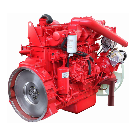
DIESEL VEHICLE ENGINE
DE12
Table of
Contents
Previous
Page
Next
Page
1
2
3
4
5
Advertisement
Table of Contents
Need help?
Do you have a question about the DE12 Series and is the answer not in the manual?
Ask a question
Questions and answers
Related Manuals for Doosan DE12 Series
Engine Doosan DE12T Operation & Maintenance Manual
(176 pages)
Engine Doosan DE08TS Disassembly/Assembly
(78 pages)
Engine Doosan DE08TS Manual
For d100, d120, d150, d110s-5, d130s-5, d160s-5 (108 pages)
Engine Doosan DE08TIS Series Operation & Maintenance Manual
Diesel industrial engine (144 pages)
Engine Doosan DE12TI Operation & Maintenance Manual
Diesel vehicle engine (158 pages)
Engine Doosan DE12TIS Operation & Maintenance Manual
Diesel vehicle engine (158 pages)
Engine Doosan DV11 Operation And Maintenance Manual
(221 pages)
Engine Doosan DB33A Service Manual
Diesel engine 3.3 liter (79 pages)
Engine Doosan D35S-5 Service Manual
(366 pages)
Engine Doosan DP158L Series Operation & Maintenance Manual
Diesel generator engine (262 pages)
Engine Doosan DP158LDF Operation & Maintenance Manual
Generator diesel engine (160 pages)
Engine Doosan DL06 Operation Manual
Interim tier iv (211 pages)
Engine Doosan DL06 Manual
(207 pages)
Engine Doosan A2300 Service Manual
(242 pages)
Engine Doosan DX22 Operation & Maintenance Manual
Generator engine (208 pages)
Engine Doosan DL08 Operation & Maintenance Manual
(221 pages)
This manual is also suitable for:
De12
De12t
De12ti
De12tis
Table of Contents
Save PDF
Print
Rename the bookmark
Delete bookmark?
Delete from my manuals?
Login
Sign In
OR
Sign in with Facebook
Sign in with Google
Upload manual
Upload from disk
Upload from URL


Need help?
Do you have a question about the DE12 Series and is the answer not in the manual?
Questions and answers